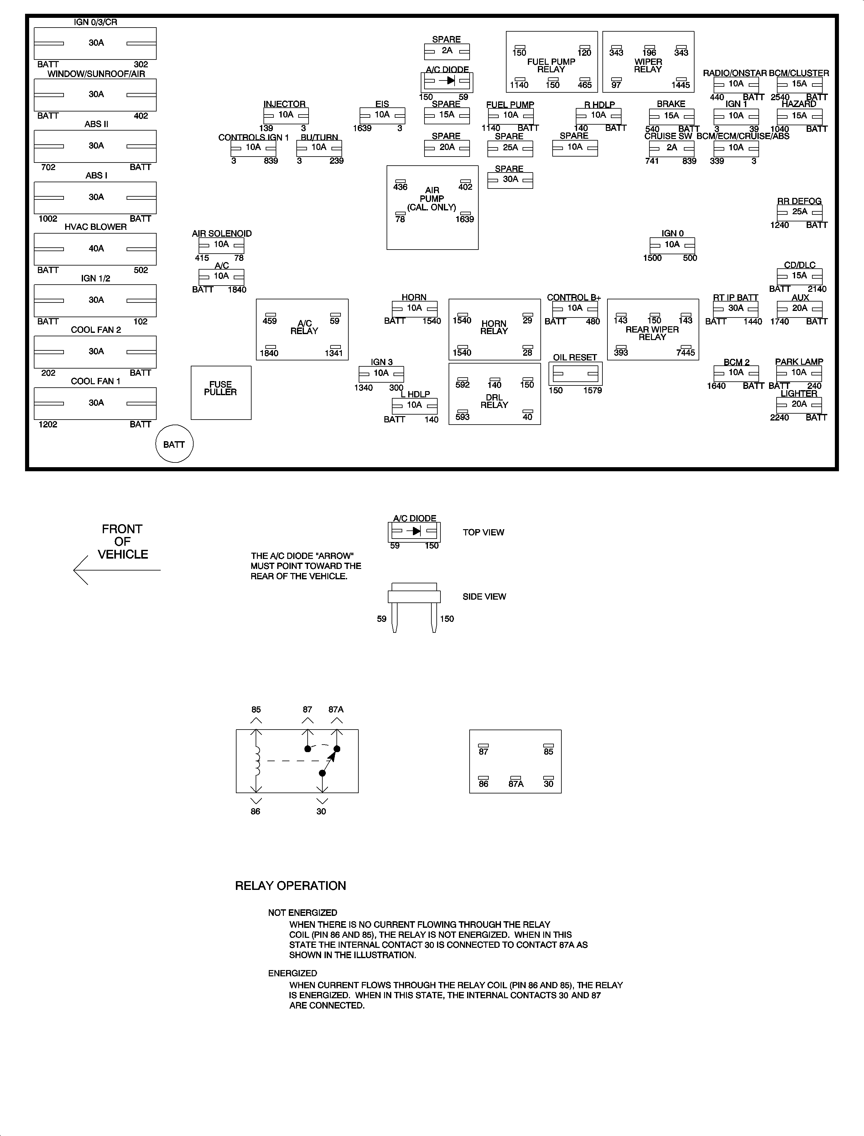
Electrical Center Identification Views L61
| Table 1: | Maxifuse/Minifuse Feeds |
| Table 2: | Relay Circuit Feeds |
| Table 3: | Misc Devices |
| Table 4: | Minifuse Circuit Feeds |
Underhood Fuse Block Diagram

Underhood Fuse Block Charts
This chart lists the maxifuses and minifuses they control.
NO. | FUSE (CB) | COLOR (AMP) | SYSTEM |
|---|---|---|---|
1 | COOL FAN 1 | Green (30) | Cooling Fan Control Module |
2 | COOL FAN 2 | Green (30) | Cooling Fan Control Module |
3 | IGN 1/2 | Green (30) | Ignition Switch |
4 | IGN 0/3/CR | Green (30) | Ignition Switch |
5 | ABS I | Green (30) | Electronic Brake/Traction Control Module |
6 | ABS II | Green (30) | Electronic Brake/Traction Control Module |
7 | HVAC BLOWER AMBER | Green (30) | HVAC Blower Relay |
8 | WDO/SUNROOF/AIR | Circuit Breaker (30) | Window Relay/Sunroof Assembly/Secondary Air |
The following chart lists the relays located in the underhood fuse block, and the systems they control.
RELAY | MAXIMUM LOAD | SYSTEM |
|---|---|---|
DRL | 20 Amp | Daytime Running Lamps |
HORN | 20 Amp | Horn |
A/C | 20 Amp | A/C Compressor |
The following chart lists the devices located in the underhood fuse block, and the systems they control.
DEVICE | SYSTEM |
|---|---|
Oil Life Reset | Body Control Module |
A/C Diode | A/C Compressor |
Fuse Puller | None |
The following chart lists the minifuses located in the underhood fuse block, and the circuits they feed.
FUSE | COLOR (AMP) | SYSTEM |
|---|---|---|
LIGHTER | Yellow (20) | Cigar Lighter |
LHDLP | Blue (15) | Left Headlamp - High and Low Beam |
RHDLP | Blue (15) | Right Headlamp - High and Low Beam |
BCM 2 | Red (10) | Body Control Module |
IGN 3 | Red (10) | Evaporative Emission Canister Purge Solenoid/Cruise Clutch Switch/EVAP Vent Solenoid/Heat Oxygen Sensor 2 |
AUX | Yellow (20) | Auxiliary Power Outlet |
RT IP BATT | Green (30) | Door Locks/Heat Mirror Relay/Power Seat/Premium Sound Amplifier/Fog Lamp Relay |
CONTROL B+ | Red (10) | Powertrain Control Module |
HORN | Red (10) | Horn Relay |
FUEL PUMP | Blue (15) | Fuel Pump Relay |
A/C | Red (10) | A/C Relay |
IGN 0 | Red (10) | Powertrain Control Module |
RR DEFOG | Natural (25) | Rear Defog Relay |
BCM/ECM/CRUISE/ABS | Red (10) | Electronic Brake/Traction Control Module/Cruise Control Module/Body Control Module/Cruise Brake Switch/Cruise Switch Fuse |
CRUISE SW | Grey (2) | Horn/Cruise Switch |
INJ | Red (10) | Fuel Injectors |
CONTROLS IGN 1 | Red (10) | Powertrain Control Module/Cooling Fan Control Module/Automatic Transaxle |
HAZARD | Blue (15) | Hazard Switch |
IGN 1 | Red (10) | I/P Cluster/Coolant Level Switch/Electronic PRNDL Module/Sensing and Diagnostic Module |
BRAKE | Blue (15) | Stop Lamp Switch |
PARK LP | Red (10) | Headlamp/Turn Signal Switch |
EIS | Red (10) | Electronic Ignition Module |
BU/TURN | Red (10) | Park/Neutral Position Switch/Back-Up Switch/Hazard Switch |
BCM/CLUSTER | Blue (15) | Body Control Module/I/P Cluster/Decklid Release/Dimmer Switch |
RADIO | Red (10) | Radio |
CD/DLC | Blue (15) | Data Link Connector/Radio |
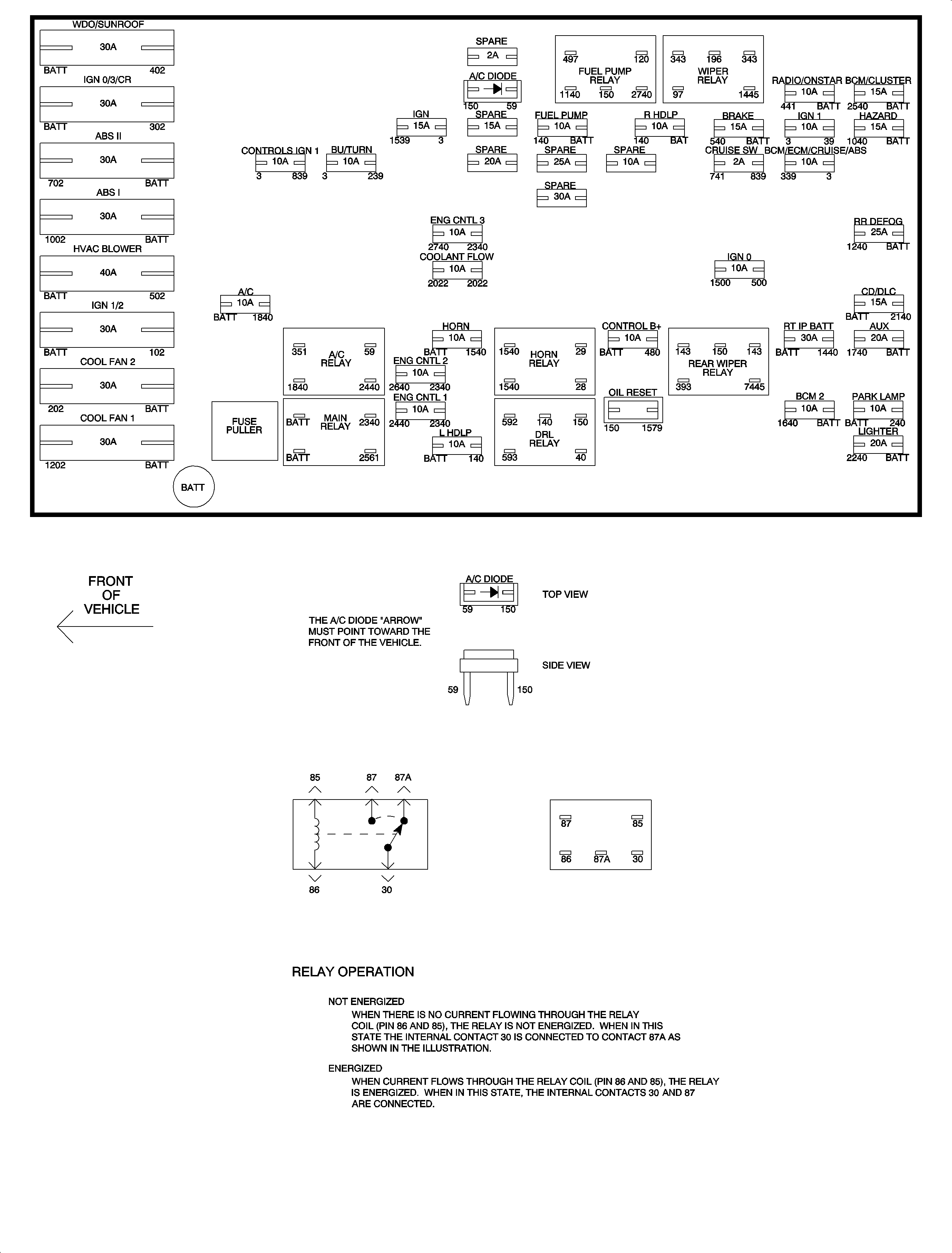
Electrical Center Identification Views L81
| Table 1: | Maxifuse/Minifuse Feeds |
| Table 2: | Relay Circuit Feeds |
| Table 3: | Misc Devices |
| Table 4: | Minifuse Circuit Feeds |
Underhood Fuse Block Diagram

Underhood Fuse Block Charts
This chart lists the maxifuses and minifuses they control.
NO. | FUSE (CB) | COLOR (AMP) | SYSTEM |
|---|---|---|---|
1 | COOL FAN 1 | Green (30) | Cooling Fan Control Module |
2 | COOL FAN 2 | Green (30) | Cooling Fan Control Module |
3 | IGN 1/2 | Green (30) | Ignition Switch |
4 | IGN 0/3/CR | Green (30) | Ignition Switch |
5 | ABS I | Green (30) | Electronic Brake/Traction Control Module |
6 | ABS II | Green (30) | Electronic Brake/Traction Control Module |
7 | HVAC BLOWER | Green (30) | HVAC Blower Relay |
8 | WDO/SUNROOF/AIR | Circuit Breaker (30) | Window Relay/Sunroof Assembly |
The following chart lists the relays located in the underhood fuse block, and the systems they control.
RELAY | MAXIMUM LOAD | SYSTEM |
|---|---|---|
DRL | 20 Amp | Daytime Running Lamps |
MAIN | 20 Amp | Engine Control 1/2/3 Fuses |
HORN | 20 Amp | Horn |
A/C | 20 Amp | A/C Compressor |
The following chart lists the devices located in the underhood fuse block, and the systems they control.
DEVICE | SYSTEM |
|---|---|
Oil Life Reset | Body Control Module |
A/C Diode | A/C Compressor |
Fuse Puller | None |
The following chart lists the minifuses located in the underhood fuse block, and the circuits they feed.
FUSE | COLOR (AMP) | SYSTEM |
|---|---|---|
LIGHTER | Yellow (20) | Cigar Lighter |
LHDLP | Blue (15) | Left Headlamp - High and Low Beam |
RHDLP | Blue (15) | Right Headlamp - High and Low Beam |
BCM2 | Red (10) | Body Control Module |
ENG CNTL 1 | Red (10) | A/C Relay, Mass Airflow Sensor, Evaporative Emission Canister Purge Solenoid, Heated Oxygen Sensor Bank 2, Sensors 1 and 2 Linear Exhaust Gas Recirculation Valve |
ENG CNTL 2 | Red (10) | Fuel Injectors, Variable Intake Manifold Solenoid |
AUX | Yellow (20) | Auxiliary Power Outlet |
RT IP BATT | Green (30) | Door Locks/Heat Mirror Relay/Power Seat/Premium Sound Amplifier/Fog Lamp Relay |
ENG CNTL 3 | Green (30) | Heated Oxygen Sensor Bank 1 Sensors 1 and 2, Engine Control Module Fuel Pump Relay, EVAP Vent Solenoid |
CONTROLS B+ | Red (10) | Engine Control Module/Transmission Control Module |
HORN | Red (10) | Horn Relay |
FUEL PUMP | Blue (15) | Fuel Pump Relay |
A/C | Red (10) | A/C Relay |
IGN 0 | Red (10) | Park/Neutral Position Switch/Park Lock/PRNDL/PCM |
RR DEFOG | Natural (25) | Rear Defog Relay |
BCM/ECM/CRUISE/ABS | Red (10) | Electronic Brake/Traction Control Module/Engine Control Module/Body Control Module/Cruise Brake Switch/Cruise Switch Fuse |
CRUISE SW | Grey (2) | Horn/Cruise Switch |
CONTROLS IGN 1 | Red (10) | Transaxle Control Module/Cooling Fan Control Module |
HAZARD | Red (10) | Hazard Switch |
IGN 1 | Red (10) | I/P Cluster/Coolant Level Switch/Electronic PRNDL Module/Sensing and Diagnostic Module |
BRAKE | Blue (15) | Stop Lamp Switch |
PARK LP | Red (10) | Headlamp/Turn Signal Switch |
IGN | Blue (15) | Ignition Coils |
BU/TURN | Red (10) | Park/Neutral Position Switch/Coolant Flow Pump/Hazard Switch |
BCM/CLUSTER | Blue (15) | Body Control Module/I/P Cluster/Decklid Release/Dimmer Switch |
Radio | Red (10) | Radio |
CD/DLC | Blue (15) | Data Link Connector/Radio |
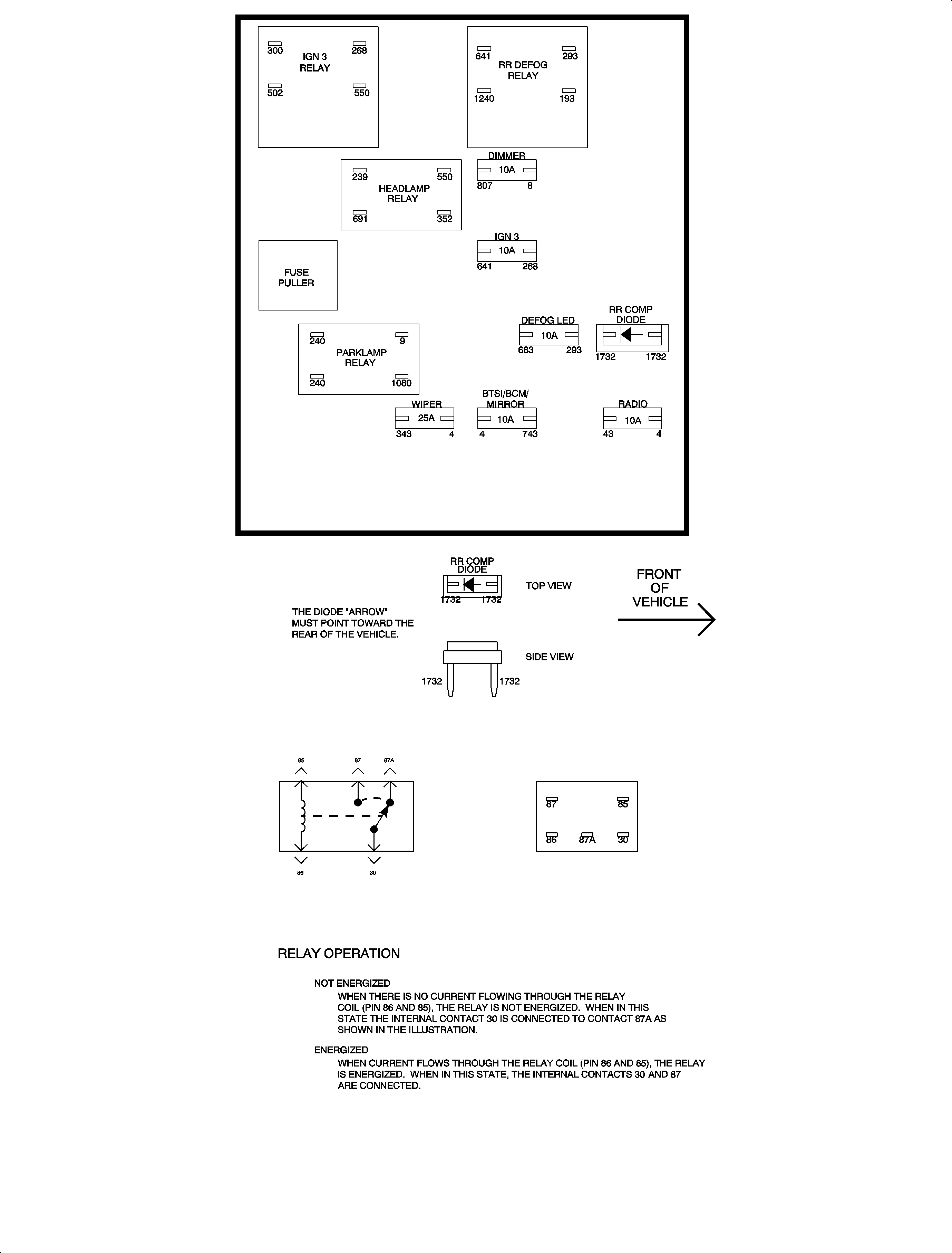
Electrical Center Identification Views Left
| Table 1: | Minifuse Circuit Feeds |
| Table 2: | Relay/Module Circuit Feeds |
| Table 3: | Misc Devices |
Instrument Panel Fuse Block Diagram

Instrument Panel Fuse Block Charts
The following chart lists the minifuses located in the left instrument panel fuse block, and the systems they control.
FUSE | COLOR (AMP) | SYSTEM |
|---|---|---|
RADIO | Red (10) | Radio |
BTSI/BCM/MIRROR | Red (10) | BTSI Solenoid/Parklock Switch/Body Control Moudle/Power Mirror Switch |
WIPER | Natural (25) | Wiper Relay/Wiper Switch/Front Wiper Motor |
DEFOG LED | Red (10) | Rear Defog Switch |
IGN 3 | Red (10) | Rear Defog Relay/HVAC Control Head/Vehicle Speed Signal Conditioner Module/Traction Control/Passenger Heated Seat Switch/Fog Lamp/Driver Heated Seat Switch |
HVAC SW | Yellow (20) | HVAC Control Head |
DIMMER | Red (10) | Dimmer |
The following chart lists the devices located in the left fuse block, and the systems they control.
RELAY | MAXIMUM LOAD | SYSTEM |
|---|---|---|
WIPER | 20 Amp | Wiper Switch/Wiper Motor |
RR DEFOGGER | 20 Amp | Rear Defog Switch/Rear Defog Grid |
FUEL PUMP | 20 Amp | Fuel Pump |
HVAC BLOWER | 35 Amp | HVAC Control Head/Blower Motor |
The following chart lists the devices located in the left instrument panel fuse block and the systems they control.
DEVICE | SYSTEM |
|---|---|
RR Comp Diode | Liftgate/Decklid Ajar Switch |
Fuse Puller | None |
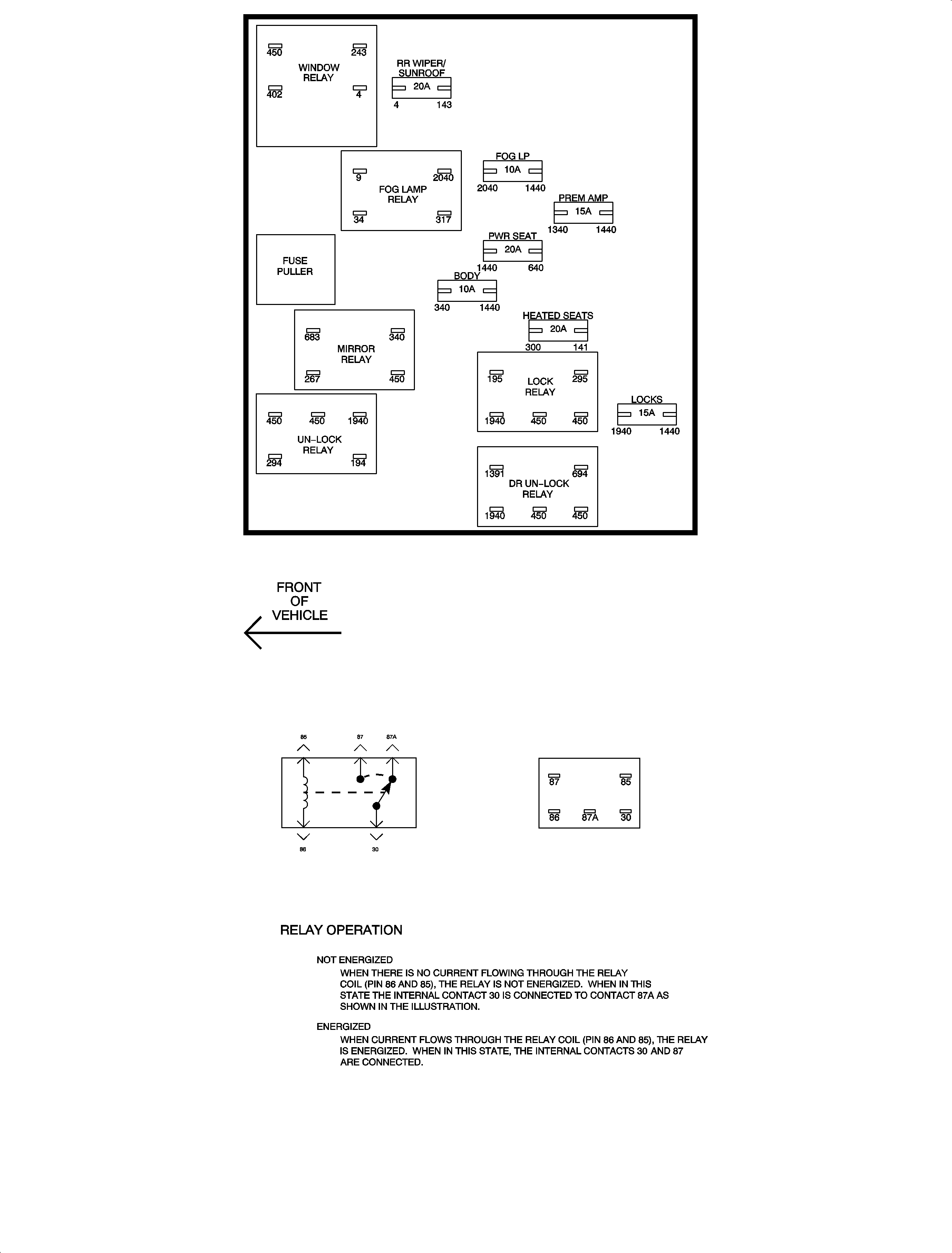
Electrical Center Identification Views Right
| Table 1: | Minifuse Circuit Feeds |
| Table 2: | Relay/Module Circuit Feeds |
| Table 3: | Misc Devices |
Instrument Panel Fuse Block Diagram

Instrument Panel Fuse Block Charts
The following chart lists the minifuses located in the left instrument panel fuse block, and the systems they control.
FUSE | COLOR (AMP) | SYSTEM |
|---|---|---|
LOCKS | Blue (15) | Door Lock/Unlock Relays |
PWR SEAT | Yellow (20) | Drivers Power Seat Switch |
BODY | Red (10) | Heated Mirror Relay/Liftgate Key Cylinder Switch/Door Lock Switch |
FOG LP | Red (10) | Fog Lamp Relay |
PREM AMP | Blue (15) | Amplifier |
HEATED SEATS | Yellow (20) | Heated Seat |
WIPER/SUNROOF | Yellow (20) | Rear Wiper Relay/Rear Wiper Motor/Sunroof Assembly |
The following chart lists the devices located in the left fuse block, and the systems they control.
RELAY | MAXIMUM LOAD | SYSTEM |
|---|---|---|
DR UNLOCK | 20 Amp | Door Lock Motor |
UNLOCK | 20 Amp | Door Lock Motor |
LOCK | 20 Amp | Door Lock Motor |
MIRROR | 20 Amp | Mirror Switch/Mirror |
FOG LAMP | 20 Amp | Fog Lamp Switch/Fog Lamps |
RR WIPER | 20 Amp | Rear Wiper Switch/Rear Wiper Motor |
WINDOWS | 35 Amp | Window Switch/Sunroof Assembly |
The following chart lists the devices located in the left instrument panel fuse block and the systems they control.
DEVICE | SYSTEM |
|---|---|
Fuse Puller | None |
