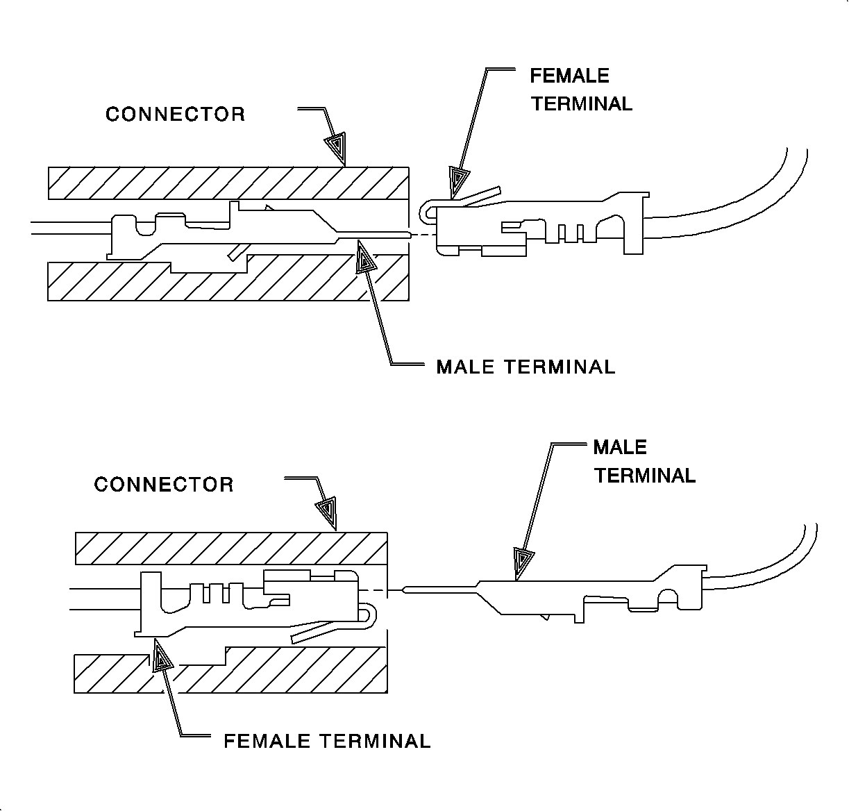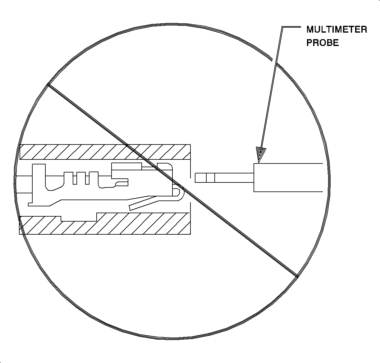
Important: Do not push multimeter probes into the connector terminals.
These devices are made of a short length of wire, a terminal, and a diagnostic service probe or an alligator clip J-35616
These jumpers are color coded. Check the connector face view section to verify which jumper is used with the connector that is being probed.
They have a dual purpose. The first being to aid in measuring voltage, resistance, or current at a connector. Since diagnostic service probes are limited to use on 0.35, 0.50, and 0.80 2 mm, (22, 20, and 18 gage) thin wall wire, many of the wires cannot be probed without disconnecting the connector. But, probing the terminal could spread the contacts and damage them. Once a contact is damaged it is very difficult to make good contact with a male terminal. By using the test adapters, the probe can make excellent contact with the circuit through the diagnostic service probe or the alligator clip, and the terminal won't be damaged.

The second function is to determine if a terminal's contacts have been spread apart, resulting in an open or intermittent open. This is known as a terminal tightness test. Connector terminals make contact with the pin by means of a tang which is sprung against the pin. If the tang is spread apart by a meter probe, the tang will not spring back to tightly grip the pin. Test this by inserting the jumper pin and removing it, noting how well the terminal holds the pin. It should be held well enough that the pin will not fall out of the terminal.
Sneak Circuits
Understanding sneak circuits can help in quickly diagnosing electrical problems that can, at first, seem very complicated.
A sneak circuit can be defined as an unplanned complete circuit. This type of failure is different than a SHORT CIRCUIT.
A sneak circuit can occur when more than one component is using the same ground path or power feed. Sneak circuits can happen if a common ground is lost, a fuse is blown, or a wire is grounded between components.
The most visible sneak circuit on the Saturn vehicle is the headlamp circuit. The headlamp circuits are fed by two fuses, the left headlamp fuse and the right headlamp fuse. Note that the left headlamp fuse feeds both the high and low beam bulbs on the left side of the vehicle. Likewise, the right headlamp fuse feeds both the high and low beam bulbs on the right side of the vehicle. On the ground side of the headlamp circuit the important thing to notice is that both the left and right low beam bulbs are switched on and off together. Likewise, both the left and right high beam bulbs are switched on and off together.
If the left or right headlamp fuse blows, evidence of the sneak circuit will be the headlamp bulbs on the side of the blown fuse will be dimmer than the other headlamp bulb. This is caused by the sneak circuit from the good headlamp fuse, through the bulbs, to the ground through the headlamp switch.
