Circuit Description
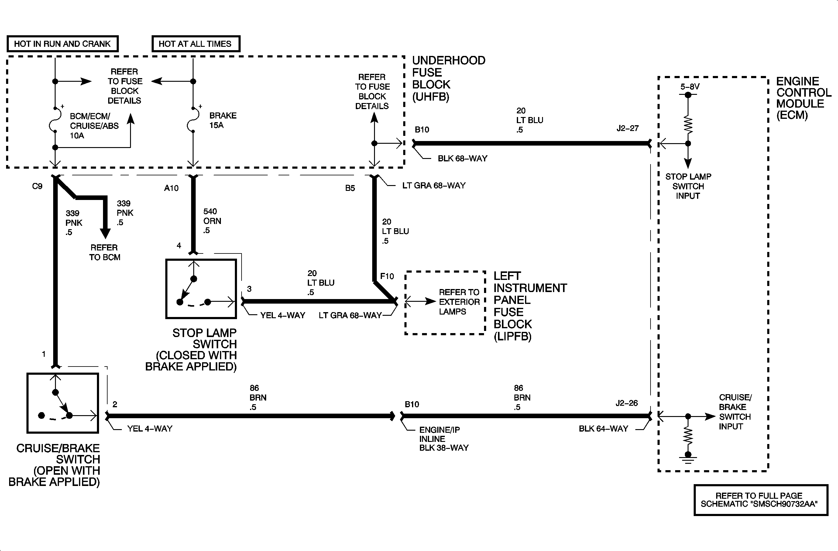
The cruise brake switch and the stop lamp switch are brake pedal inputs to the ECM to determine if the brake pedal is applied or released. Ignition voltage is supplied at the cruise brake switch input to the ECM whenever the ignition is turned On and the brake pedal is released (switch closed). If the brake pedal is applied, the cruise brake switch input at the ECM will go low. The ECM stop lamp switch circuit works the opposite. Battery voltage is supplied at the stop lamp switch input to the ECM whenever the brake pedal is applied (switch closed). If the brake pedal is released, the stop lamp switch input at the ECM will go low. If the stop lamp switch input at the ECM were to open, the switch input would read between 5-7 volts (ECM pull-up voltage). The ECM monitors both brake switches by making sure they both transition (one changes from high, while the other changes to low or vice versa) together within a certain amount time from each other. If one switch transitions and the other does not, then one of the two switches contains a circuit fault or is not adjusted correctly. DTC P0571 will set if the cruise brake or stop lamp switch input at the ECM changes state for longer than 1 second, while the other did not for a certain number of consecutive times in one ignition cycle.
Conditions for Running the DTC
DTC P0571 will set if the ECM detects that the cruise brake switch input or stop lamp switch input changed state (low to high or high to low) while the other switch did not change state for longer than 1 second when:
Condition exists for 20 consecutive times in one ignition cycle
DTC P0571 diagnostic runs continuously with ignition On.
P0571 is a type C DTC
Diagnostic Aids
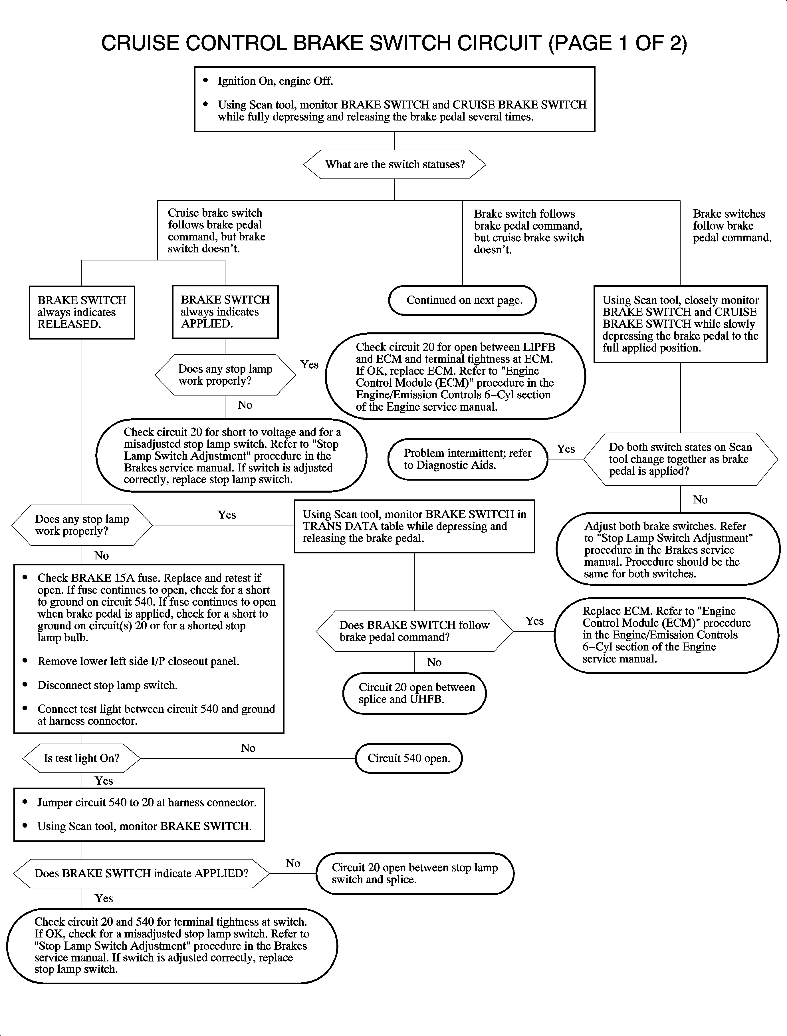
Important: Make sure both the cruise brake switch and stop lamp switches are adjusted properly. Using Scan tool, monitor both CRUISE BRAKE SWITCH and BRAKE SWITCH (stop lamp switch) while applying and releasing the brake pedal with ignition On. Both switch inputs should closely change with each other. Refer to switch adjustment procedures in the Cruise Control section of the Engine service manual if both switch inputs change, but are out of adjustment from each other.
To locate an intermittent problem, use Scan tool to monitor CRUISE BRAKE SWITCH and BRAKE SWITCH with ignition On and brake pedal released. Wiggling wires while watching for a change from RELEASED to APPLIED may locate the area where a circuit fault may exist.
NOTE: If an open in circuit 20 between the ECM and LIPFB exists, BRAKE SWITCH on Scan tool will always read APPLIED.
DTC P0571

