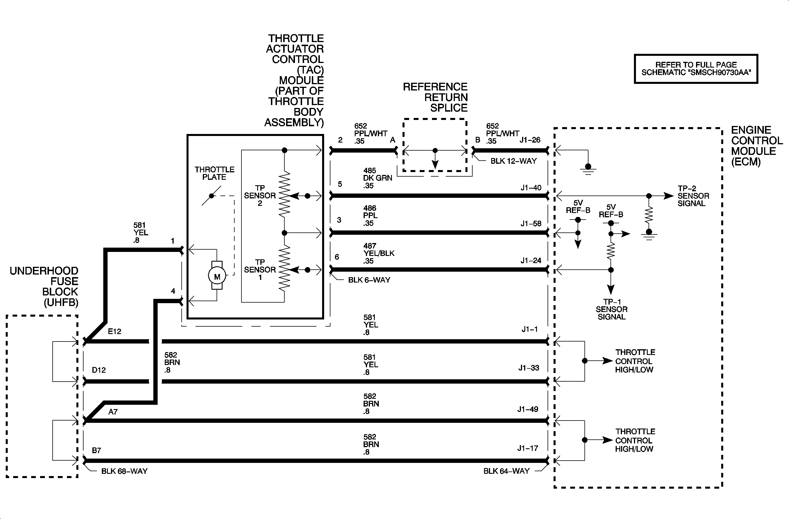
The throttle actuator control (TAC) module contains two throttle position (TP) sensors with a common 5-volt supply, a common ground, and two independent signal circuits that vary resistance according to changes in throttle plate position. The ECM measures the signal voltage from each TP sensor, which is a reduced value of the ECM 5 volt reference. As the throttle plate opens from 0% throttle to wide open throttle, the voltage on the TP sensor 1 signal increases from 0.50 volts to 4.25 volts (+/- 0.1 volts), while the voltage on the TP sensor 2 signal decreases from 4.45 volts to 0.70 volts (+/- 0.1 volts). DTC P0121 sets when TP sensor 1 and TP sensor 2 signals are out of correlation , and TP sensor 1 signal indicates too large of a difference in throttle angle based on the mass air flow (MAF) sensor signal.
DTC Parameters
DTC P0121 will set if TP sensor 1 signal voltage is not rational when:
| • | TP sensor 1 and TP sensor 2 signal voltages are out of correlation by greater than 6.25% for longer than 140 ms, while TP sensor 1 signal voltage differs from the MAF sensor signal voltage by greater than 13% for longer than 400 ms |
| • | Battery voltage greater than 7.0 volts |
| • | DTC P0122 or P0123 has not been set |
DTC P0121 diagnostic runs continuously once the above conditions have been met.
P0121 is a type A DTC for 2002, type B DTC for 2003.
NOTE: The MIL will only illuminate if the fault is present for longer than 5 seconds (2002 only).
Diagnostic Aids
Important: If DTC P0221 is also set, resistance may exist in the 5-volt Ref-B circuit 486 or reference return circuit 652. Check for corrosion and for loose or spread terminals.
A skewed TP sensor 1 can set this DTC. Monitor the voltage range of the sensor using THROTTLE ACTUATOR CONTROL in the SPECIAL FUNCTIONS section of the Scan tool, which will command the throttle actuator control module to move the throttle plate. The approximate (+/- 0.1) TP SENSOR 1 vs. TP SENSOR 2 voltage should be:
TP Sensor 1 | TP Sensor 2 |
0%/0.50 volts | 4.45 volts |
7%/0.82 volts | 4.17 volts |
25%/1.45 volts | 3.55 volts |
50%/2.45 volts | 2.55 volts |
75%/3.35 volts | 1.65 volts |
100%/4.25 to 4.60 volts | 0.70 to 0.17 volts |
If a TP sensor 1 signal circuit fault is detected, the ECM will default to REDUCED POWER mode if vehicle speed is below 56 km/h (35 mph) with APP angle at 0%. Otherwise when the circuit fault occurs, TP sensor 2 will be used and vehicle performance will not be affected.
Important: The ECM will remain in these conditions for the entire ignition cycle even if the fault is corrected.
Important: TP ANGLE on scan tool is based off of TP sensor 1 only.
