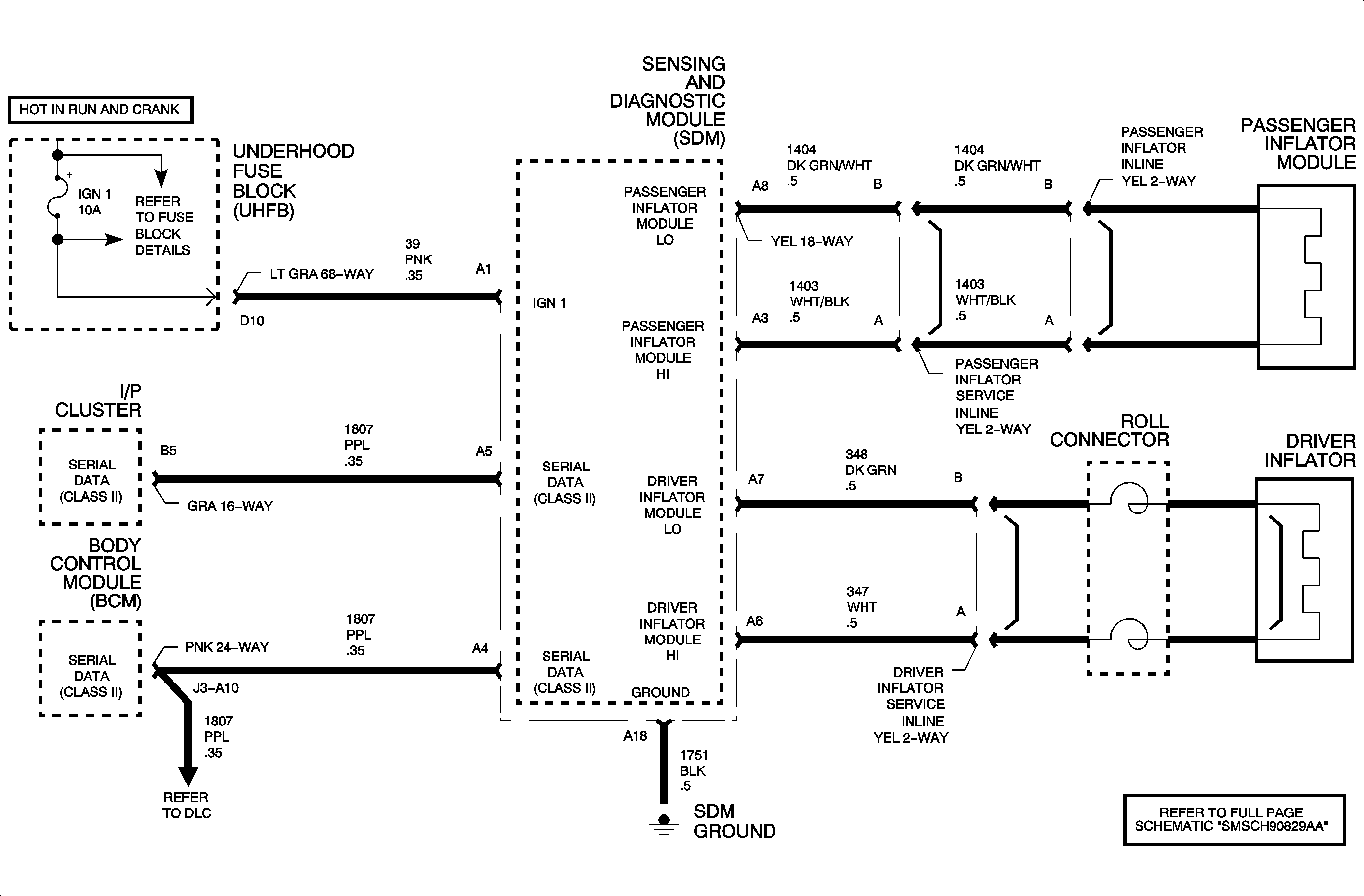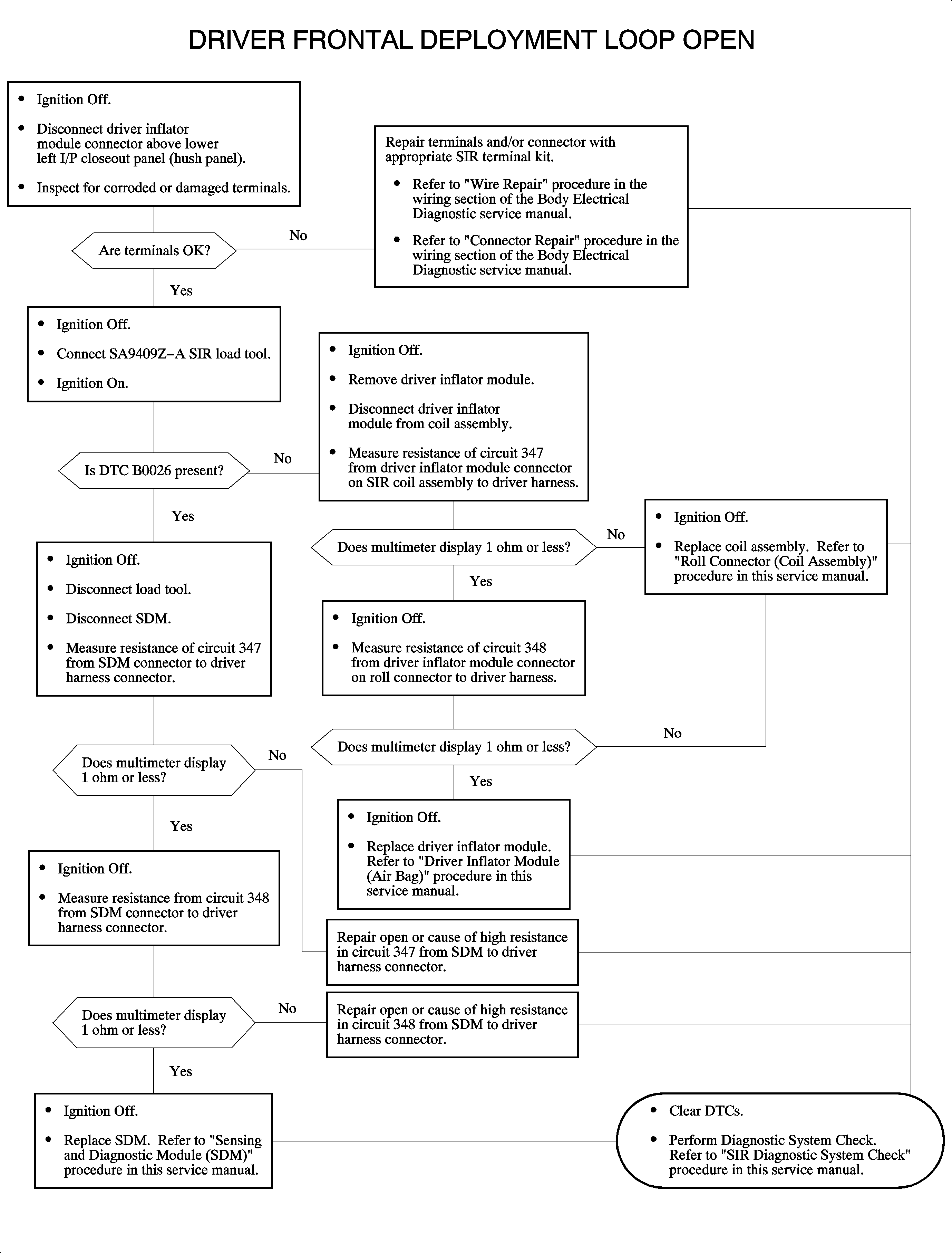
Circuit Description
When the ignition switch is turned on and during the vehicle operation, the
SDM performs a test to detect system faults. One test the SDM performs is to monitor
the driver deployment loop high circuit and driver deployment loop low circuit voltage
difference. By monitoring the voltage difference, the SDM is able to calculate the
driver loop resistance. High resistance indicates an open somewhere in the driver
deployment loop.
Conditions for Setting the DTC
DTC B0026 can be set when the driver loop resistance is high. The following
conditions must be met to set this DTC:
| • | Ignition voltage is present at the SDM and continuous. |
| • | The driver deployment loop resistance is over 4.8 ohms or circuit 347
under 2.4 volts with the loop resistance over 6 ohms. |
| • | The fault is present for half a second. |
Action Taken When the DTC Sets
| • | The air bag telltale will be on. |
Diagnostic Aids
| • | When attempting to diagnose an intermittent driver loop fault, use the
scan tool to monitor current DTCs. Wiggle the wires, turn the steering wheel, and
check the connections while watching for a current DTC to appear and/or disappear
on the scan tool. |
| • | Always start the diagnosis of the SIR DTCs with a inspection of the wiring
and the components for visible damage. |
| • | An open in the circuits 347 or 348 to the driver inflator module
could cause this DTC. |
B0026


