Circuit Description
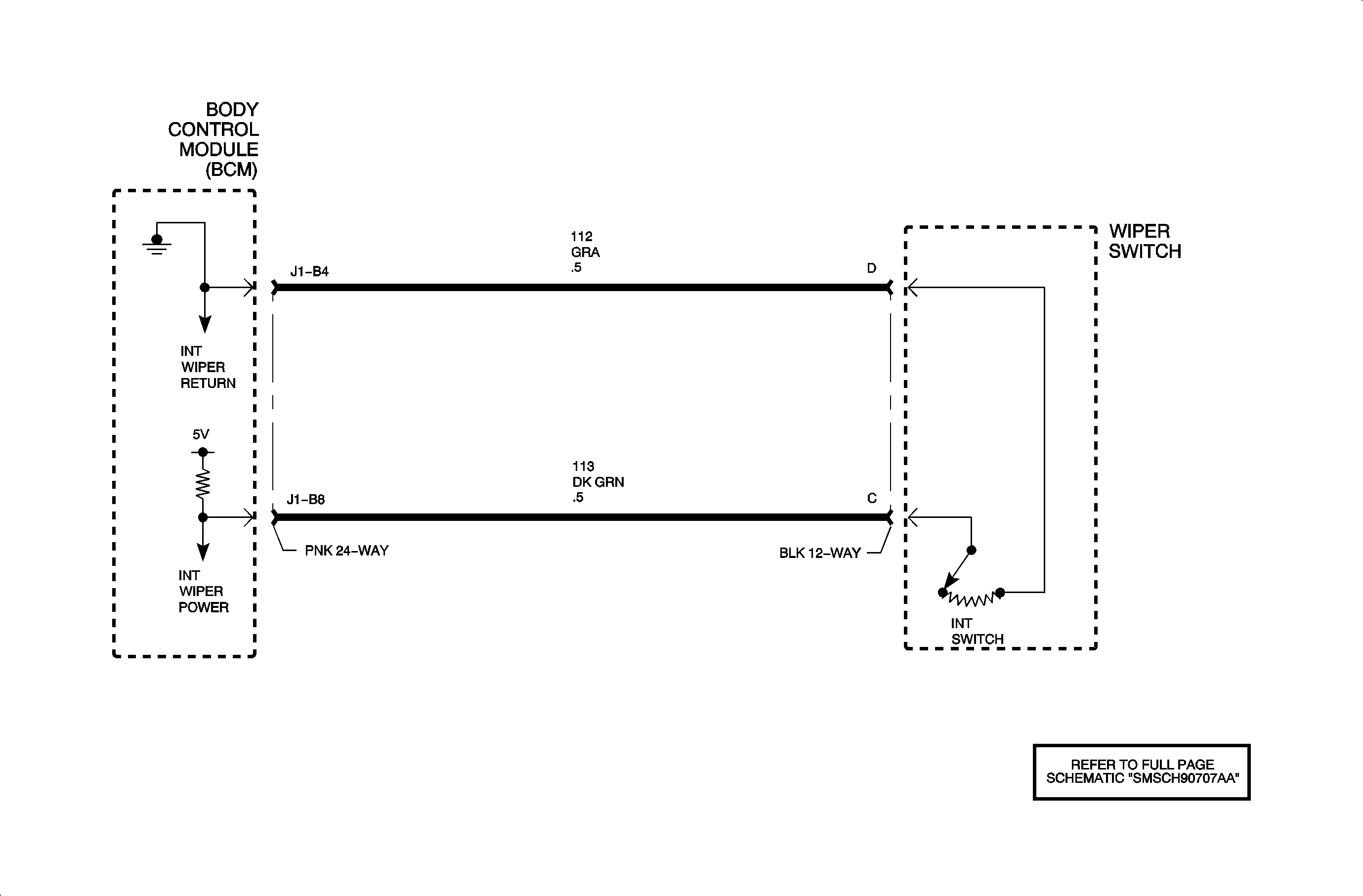
The intermittent wiper delay switch is a voltage divider connected across body
control module (BCM) inputs circuit 113 and circuit 112. The wiper relay is energized
by the BCM switching circuit 1445 to ground depending on delay switch position.
The intermittent wiper delay switch has three switch positions.
| • | Delay 1 (2000 ohms resistance, 1 swipe every 12 seconds) |
| • | Delay 2 (1000 ohms resistance, 1 swipe every 7 seconds) |
| • | Delay 3 (500 ohms resistance, 1 swipe every 2 seconds) |
Conditions for Setting the DTC
| • | Ignition is in RUN or ACC position |
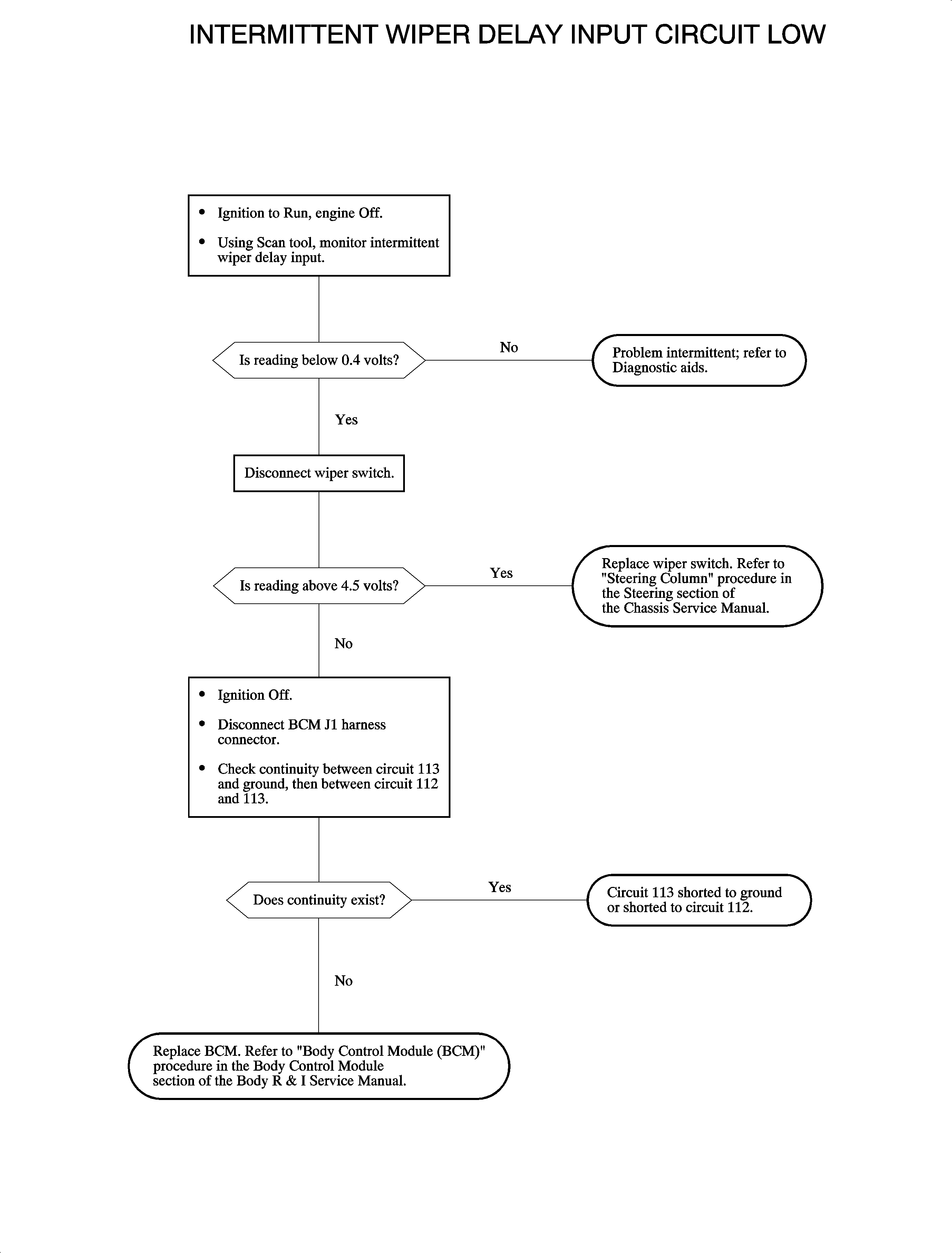
| • | Circuit 113 shorted to ground or less than 0.20 volts |
| • | No light will illuminate in I/P. |
Diagnostic Aids
| • | Inspect wiring harness for damage. Check for broken or chaffed insulation. |
| • | If fault is suspected to be intermittent, wiggling harness wiring may
help in locating fault. |
| • | Cannot vary wiper speed. |
| • | Check for poor connection at the BCM. Inspect harness connectors for backed
out terminals, improper terminal mating, broken connector locks, improperly formed
or damaged terminals and poor terminal-to-wire connection (terminal crimped over wire
insulation and not conductors). |


