Tools Required
J 43628 Frame Alignment Fixture
Removal Procedure
- Remove the intermediate steering shaft from the steering gear. Refer to Intermediate Steering Shaft Replacement in Steering Wheel and Column.
- If equipped with a L81 engine, remove the exhaust manifold pipe heat shield. Refer to Exhaust Pipe Heat Shield Replacement in Engine Exhaust.
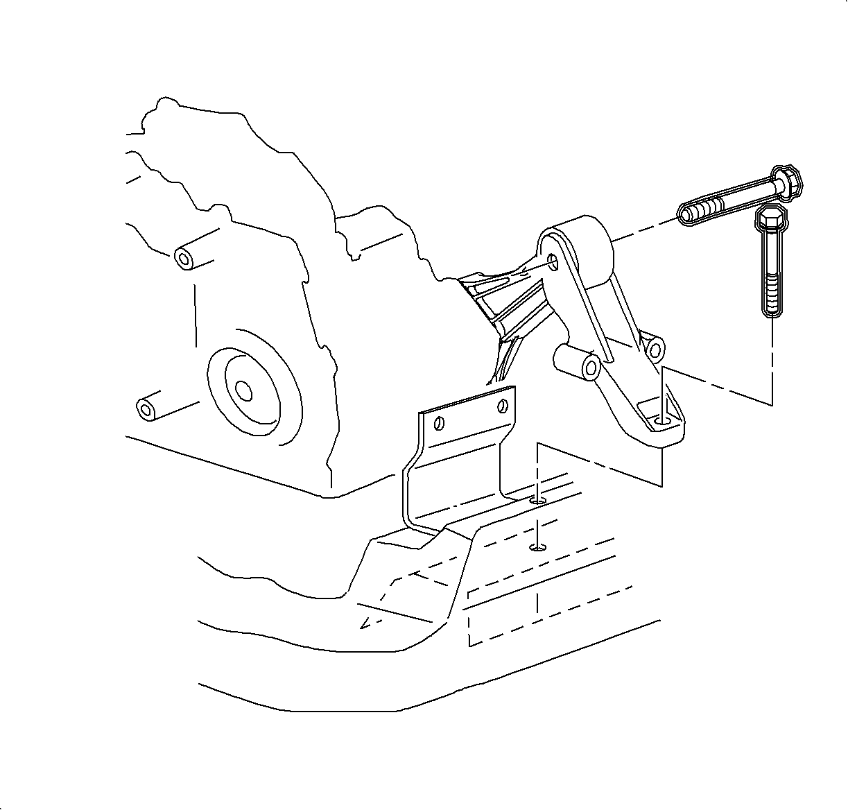
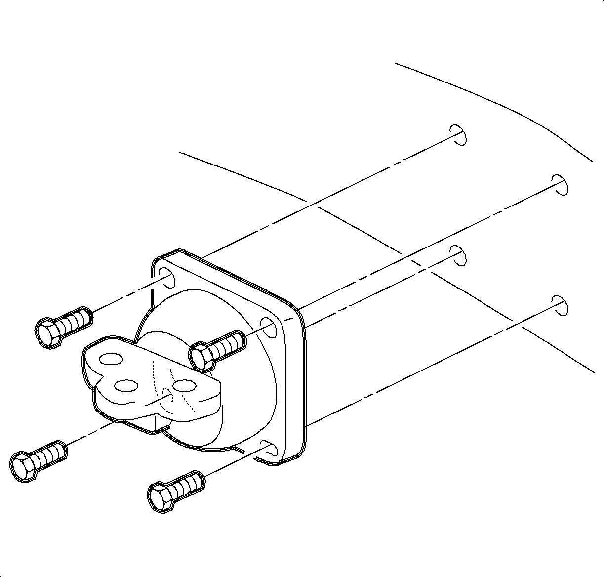
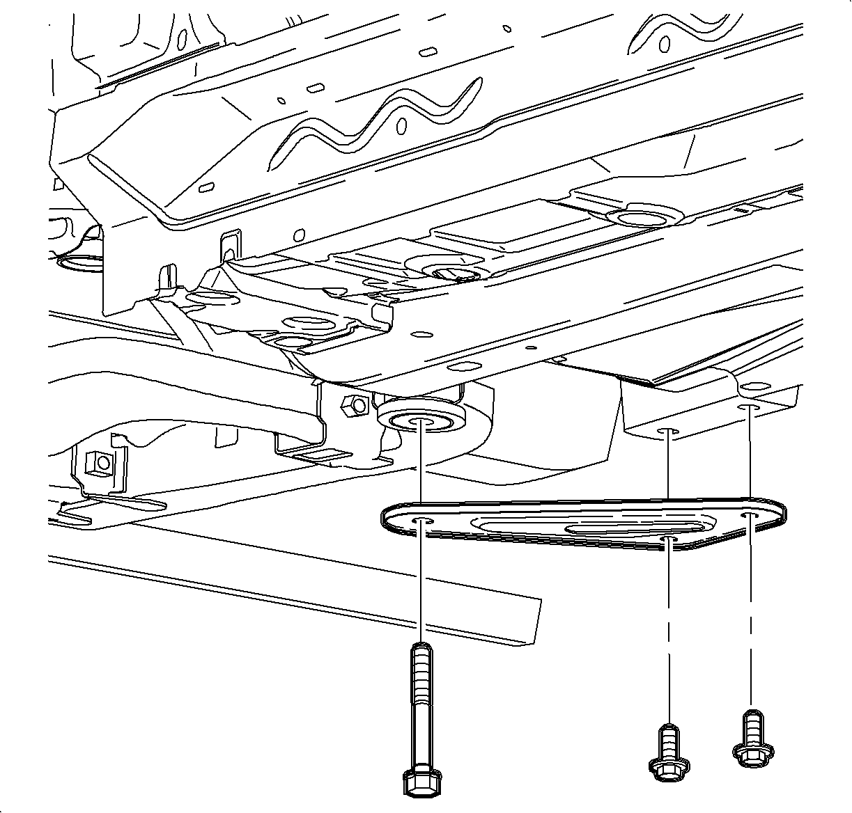
- Remove the rear transaxle mount through bolt.
- Remove the rear transaxle mount to frame bolt.
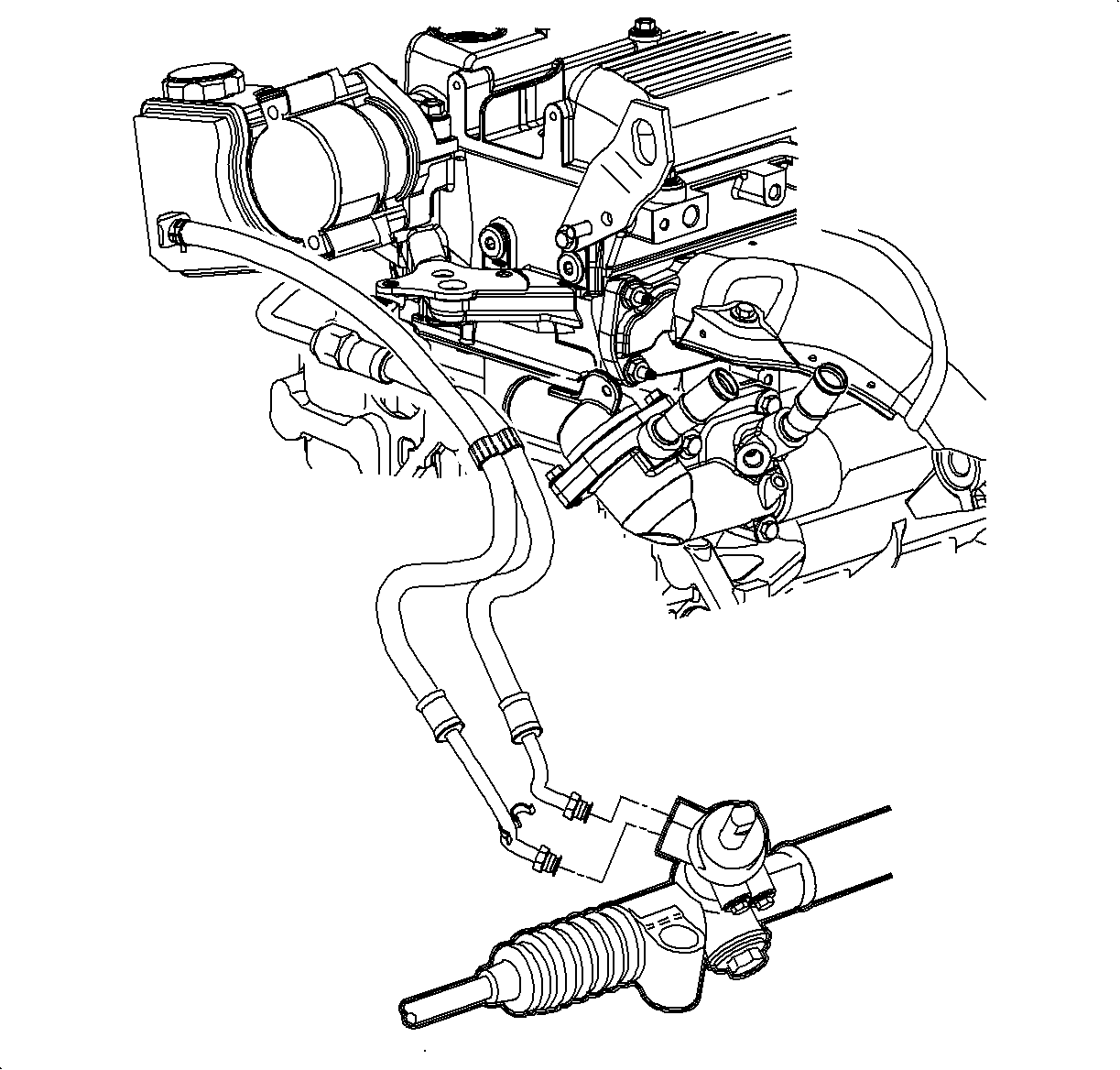
- Disconnect the power steering pressure hose from the steering gear.
- Disconnect the power steering return hose from the steering gear.
- Raise and support the vehicle. Refer to Lifting and Jacking the Vehicle in General Information.
- Remove both front tire and wheel assemblies. Refer to Tire and Wheel Removal and Installation in Tires and Wheels.
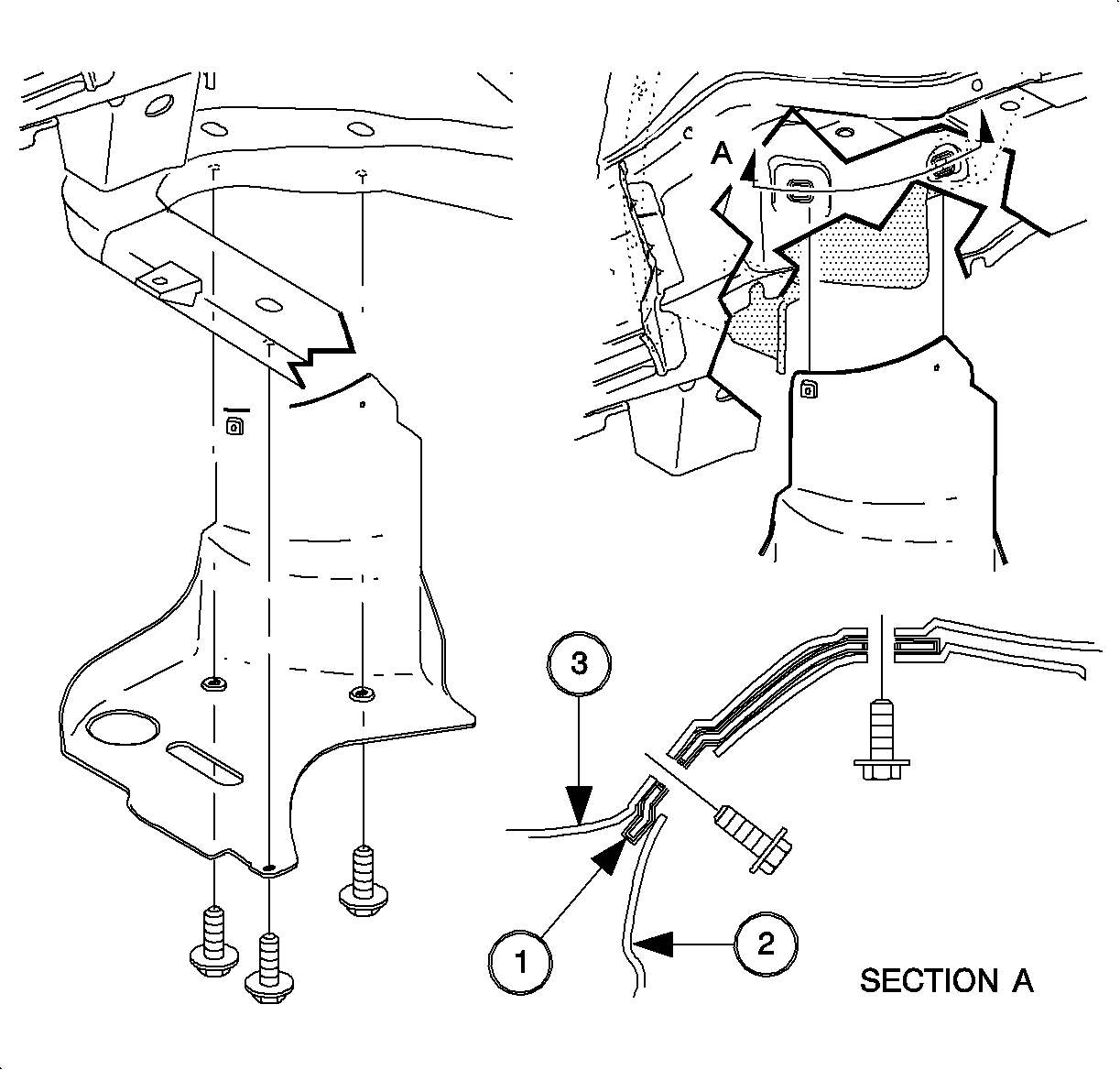
- Remove the right front lower splash shield (2).
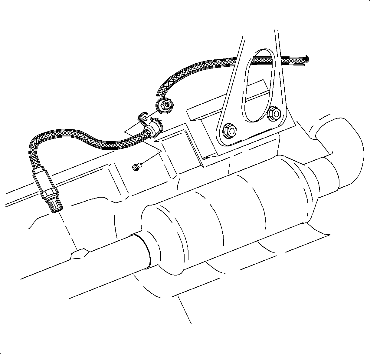
- Disconnect the O2 sensor harness connector.
- If equipped with a L61 engine, remove the O2 sensor clamp to underbody nut.
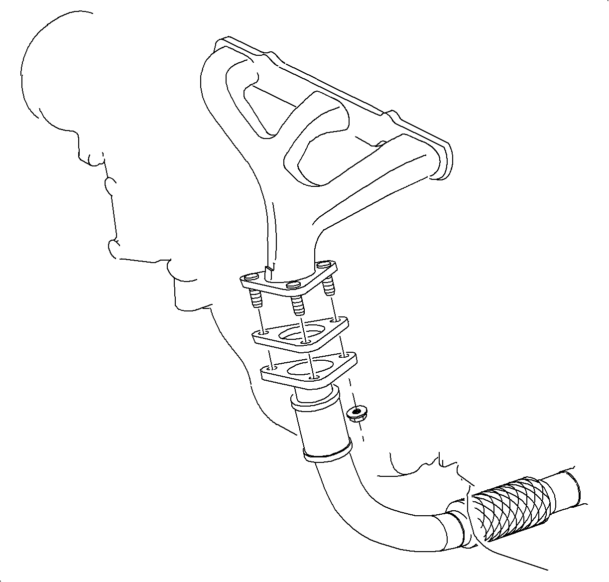
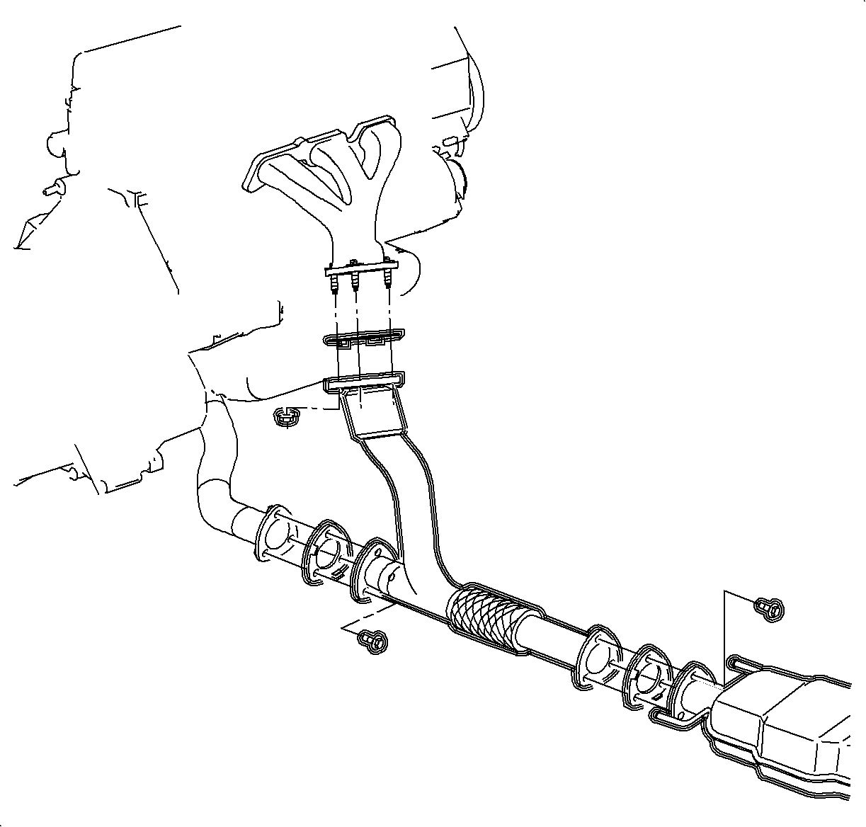
- If equipped with a L81 engine or L61 engine/manual transaxle, remove the exhaust manifold pipe. Refer to Exhaust Manifold Pipe Replacement in Engine Exhaust.
- Remove the remaining rear transaxle mount to frame bolts.
- Remove the rear transaxle mount.
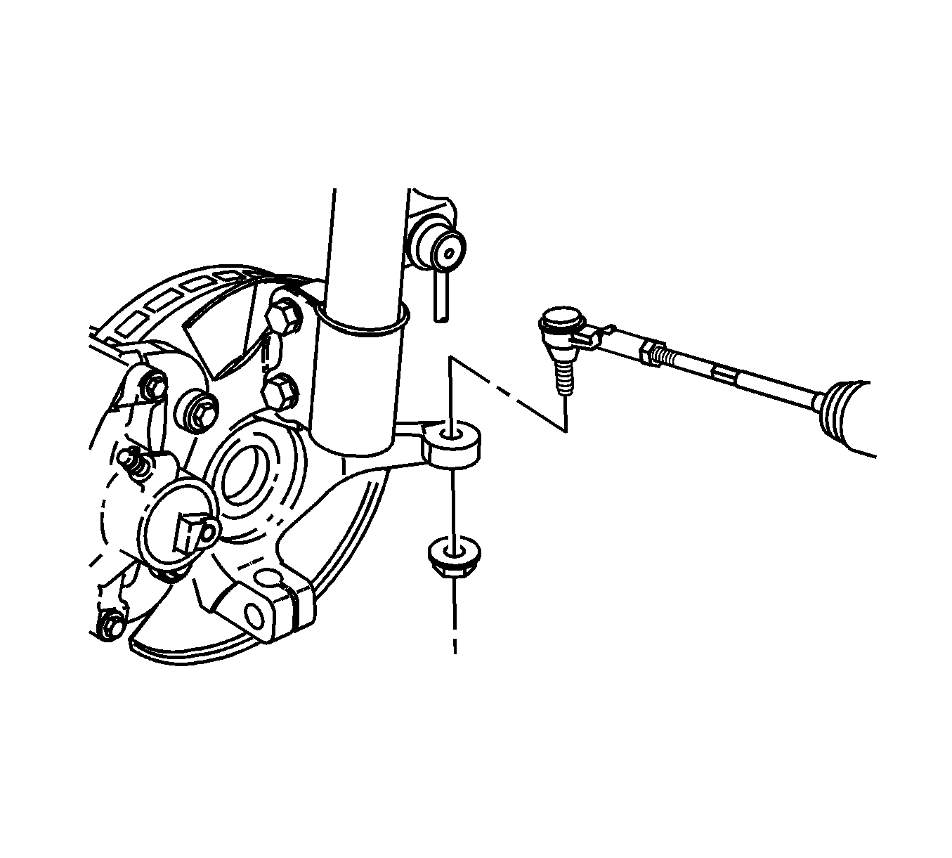
- Disconnect the outer tie rod ends from the steering knuckles. Refer to Rack and Pinion Outer Tie Rod End Replacement .
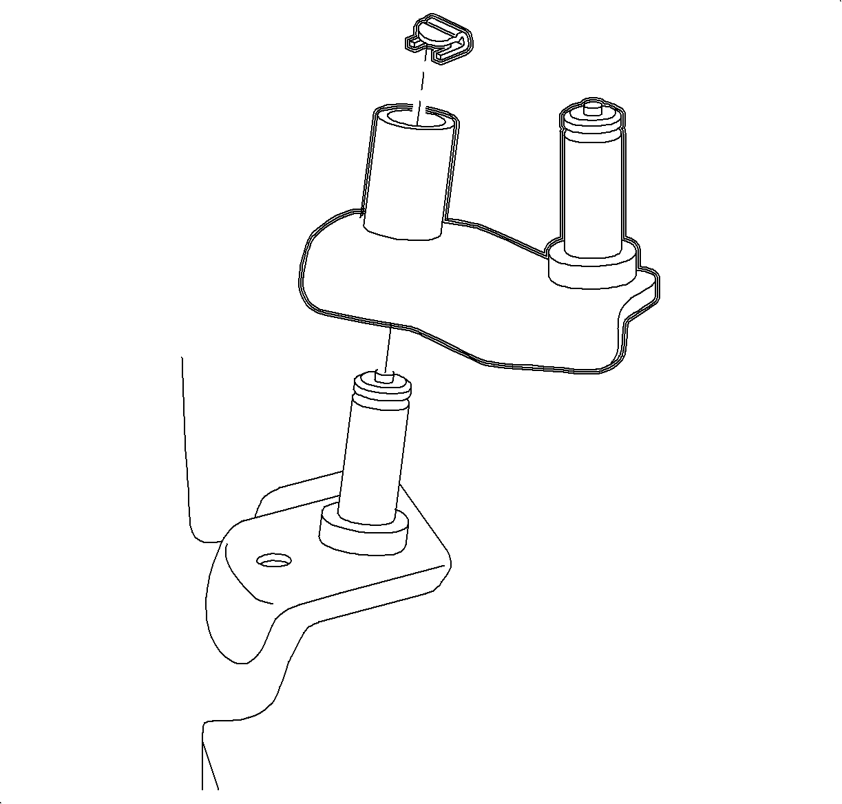
- If equipped with a L61 engine/manual transaxle, remove the shiftier link pivot pin clip.
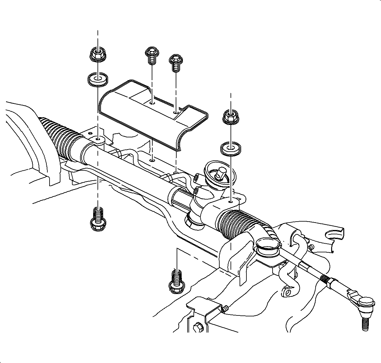
- Remove the steering gear to frame bolts. Discard the bolts.
- If equipped with a steering gear heat shield, remove the heat shield. Refer to Steering Gear Heat Shield Replacement .
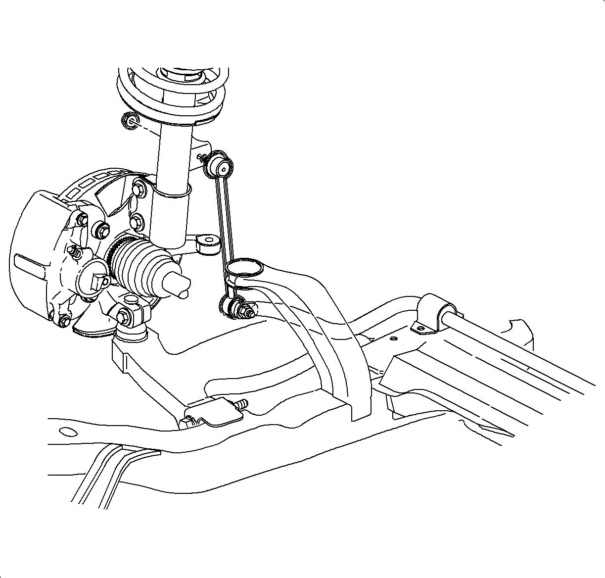
- Disconnect the stabilizer links from the struts. Refer to Stabilizer Shaft Link Replacement in Front Suspension.
- Remove the front suspension support assemblies. Discard the bolts.
- Loosen the frame to body bolts in order to achieve clearance to remove the steering gear from the vehicle through the left wheel opening.
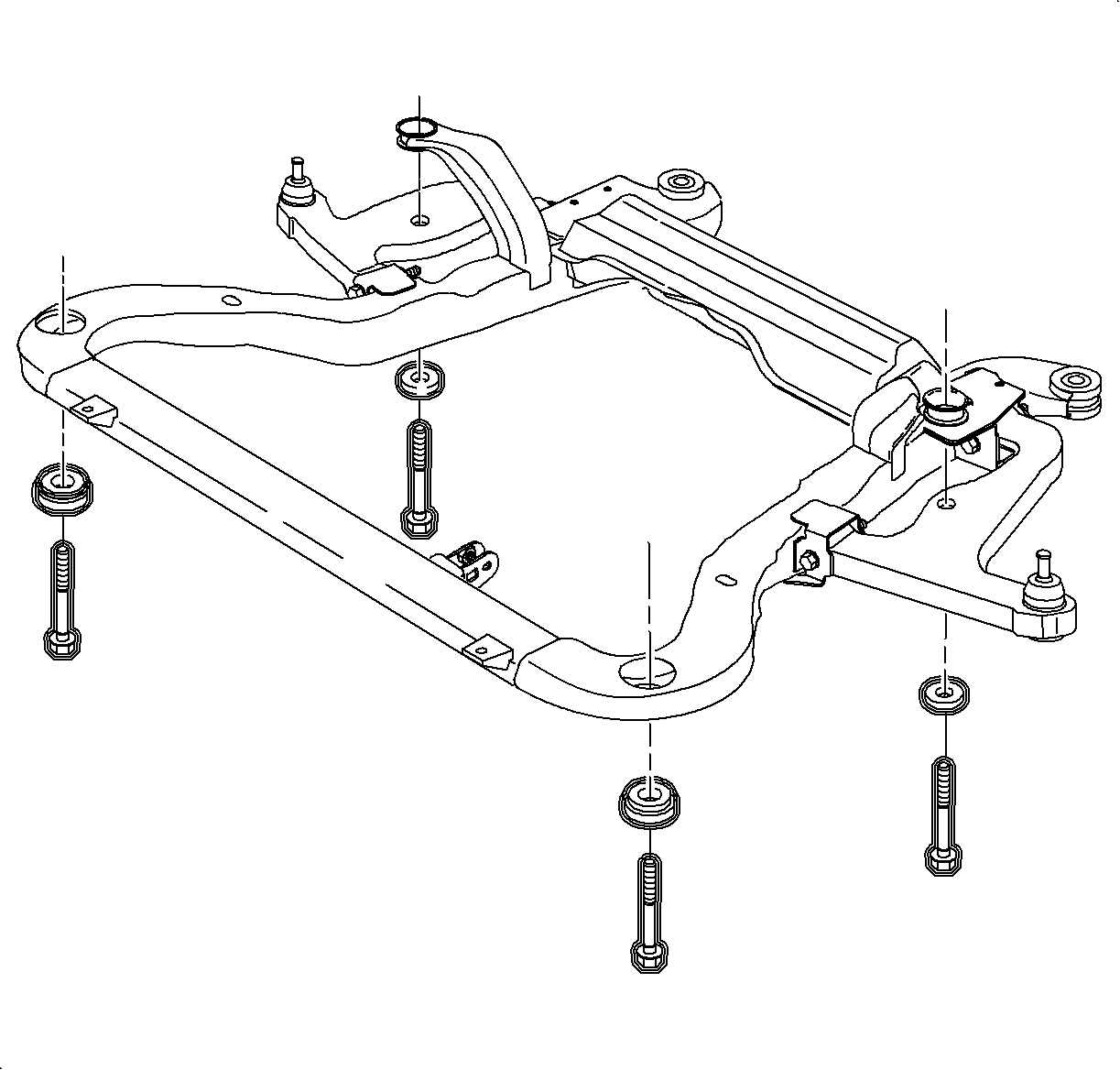
Installation Procedure
- Remove and install new frame bolts and cage nuts. Discard the bolts and nuts.
- Install the steering gear into the vehicle through the left wheel opening.
- Using the J 43628 , install the frame to the vehicle.
- Install the suspension support using new bolts.
- If equipped with a L61 engine/manual transaxle, install the shiftier link pivot pin clip.
- Install new steering gear to frame bolts.
- If equipped with a steering gear heat shield, install the heat shield. Refer to Steering Gear Heat Shield Replacement .
- Install the outer tie rod ends to the steering knuckles. Refer to Rack and Pinion Outer Tie Rod End Replacement .
- Connect the stabilizer links to the struts. Refer to Stabilizer Shaft Link Replacement .
- Install the rear transaxle mount to frame bolts.
- Connect the power steering return hose to the steering gear.
- Connect the power steering pressure hose to the steering gear.
- If equipped with a L81 engine or L61 engine/manual transaxle, install the exhaust manifold pipe. Refer to Exhaust Manifold Pipe Replacement in Engine Exhaust.
- If equipped with a L61 engine, install the O2 sensor clamp to underbody nut.
- Connect the O2 sensor harness connector.
- Install both front tire and wheel assemblies. Refer to Tire and Wheel Removal and Installation in Tires and Wheels.
- Lower the vehicle.
- Install the remaining rear transaxle mount to frame bolt.
- Install the rear transaxle mount through bolt.
- If equipped with a L81 engine, install the exhaust manifold pipe heat shield. Refer to Exhaust Pipe Heat Shield Replacement in Engine Exhaust.
- Install the intermediate steering shaft to the steering gear. Refer to Intermediate Steering Shaft Replacement in Steering Wheel and Column.
- Bleed the power steering system. Refer to Power Steering System Bleeding .
- Set the front toe. Refer to Front Toe Adjustment in Wheel Alignment.
Important:
• Do not reuse the frame bolts and cage nuts. • Replace the frame bolts and cage nuts one at a time in order to maintain
the frame in its current position.
Notice: Refer to Fastener Notice in the Preface section.

Tighten
Tighten the frame to body bolts and cage nuts to
90 N·m (66 lb ft) plus an additional 45-60 degrees.

Tighten
Tighten the bolts to 90 N·m (66 lb ft)
plus an additional 45-60 degrees.


Tighten
Tighten the steering gear to frame bolts to 45 N·m
(35 lb ft) plus an additional 90-105 degrees.


Tighten
Tighten the rear transaxle to frame bolts to 60 N·m
(44 lb ft).

Tighten
Tighten the fitting to 27 N·m (20 lb ft).
Tighten
Tighten the fitting to 27 N·m (20 lb ft).


Tighten
Tighten the nut to 4 N·m (35 lb in).

Tighten
Tighten the bolt to 60 N·m (44 lb ft).
Tighten
Tighten the bolt to 90 N·m (66 lb ft).

