For 1990-2009 cars only
Removal Procedure
- Raise and support the vehicle. Refer to Lifting and Jacking the Vehicle In General Information.
- Remove the tire and wheel. Refer to Tire and Wheel Removal and Installation in Tires and Wheels.
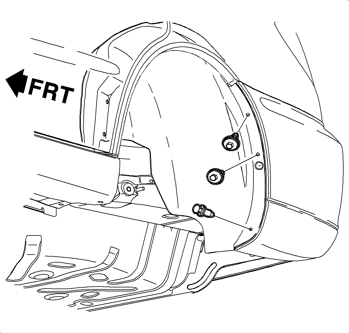
- Remove the inner wheelhouse liner.
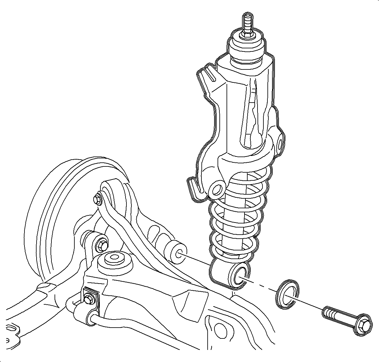
- Remove the lower shock mounting bolt. Discard the bolt.
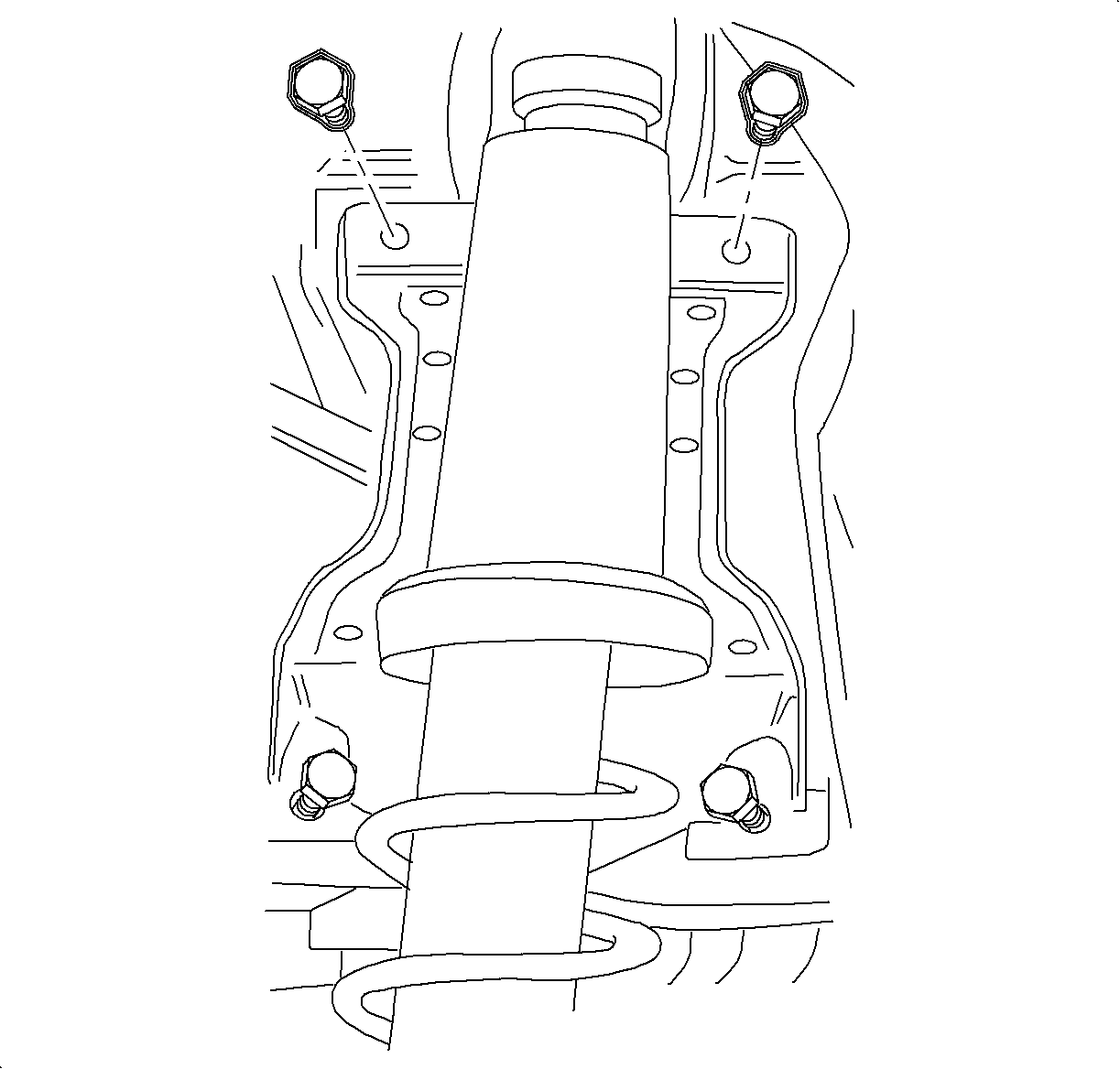
- Remove the upper carrier assembly to body bolts.
- Loosen the lower carrier assembly to body bolts.
- Lift the carrier assembly off the lower bolts in order to remove the shock assembly from the vehicle.


Important: The lower carrier bolts rest in a slotted hole/groove.
Installation Procedure
- Align the shock carrier assembly lower holes/grooves on the lower carrier bolts.
- Install the upper carrier assembly bolts.
- Install a new lower shock mounting bolt.
- Install the inner wheelhouse liner.
- Install the tire and wheel. Refer to Tire and Wheel Removal and Installation in Tires and Wheels.
- Lower the vehicle.

Notice: Refer to Fastener Notice in the Preface section.
Tighten
Tighten all the carrier to body bolts to 55 N·m (40 lb ft).

Important: A new bolt is required to ensure proper torque retention.
Tighten
Tighten the bolt to 150 N·m (110 lb ft) plus an additional
30 to 45 degrees.

