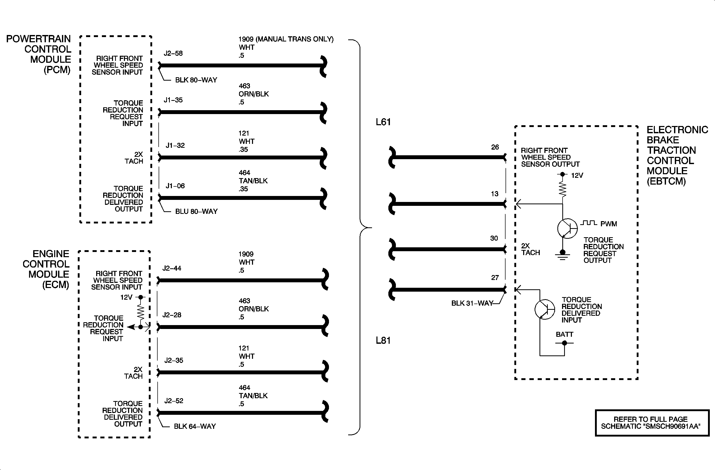
Circuit Description
The EBTCM and the PCM/ECM simultaneously control the traction control. The PCM/ECM reduces the amount of torque supplied to the drive wheels by retarding spark timing and selectively turning off the fuel injectors. The EBTCM actively applies the brakes to the front wheels in order to reduce torque.
The EBCM supplies approximately 12 volts through an internal resistor to the powertrain control module (PCM) on the delivered torque signal circuit. The PCM toggles this voltage to ground in order to create the delivered torque signal at the EBCM. A signal with a frequency of 128 Hz +/- 5 percent and a duty cycle of 25-95 percent is a valid delivered torque signal. The percentage of duty cycle is proportionate to the percentage of delivered engine torque.
Conditions for Running the DTC
| • | The ignition is ON. |
| • | The engine is running. |
Conditions for Setting the DTC
| • | The EBTCM does not receive the delivered torque signal (open or shorted circuit). |
| • | An incorrect delivered torque signal is detected by the EBTCM. |
Action Taken When the DTC Sets
Traction control will be disabled.
Diagnostic Aids
| • | It is very important that a thorough inspection of the wiring and connectors be performed. Failure to carefully and fully inspect wiring and connectors may result in misdiagnosis, causing part replacement with reappearance of the malfunction. |
| • | If an intermittent malfunction exists refer to Checking Aftermarket Accessories . |
| • | Possible causes for DTC C0244 to set: |
| - | Open in the Torque Delivered Control circuit. |
| - | Torque Delivered Control circuit shorted to ground or voltage. |
| - | Communication frequency problem. |
| - | Communication duty cycle problem. |
| - | Torque Delivered Control circuit has a wiring problem, terminal corrosion, or poor connections. |
| - | EBCM not receiving information from the PCM. |
Test Description
The numbers below refer to the step numbers on the diagnostic table.
-
This step tests for voltage supplied to the PCM from the EBCM.
-
This step tests for a shorted resistor in the EBCM or a short to voltage within the circuit, by verifying that a large voltage drop occurs in the circuit when the test lamp is placed in parallel with the DMM. The PCM may be damaged if either of these conditions is present.
Step | Action | Values | Yes | No |
|---|---|---|---|---|
Schematic Reference: Antilock Brake System Schematics Connector End View Reference: Antilock Brake System Connector End Views | ||||
1 | Did you perform the ABS Diagnostic System Check? | -- | Go to Step 2 | |
2 |
Does the DTC set? | -- | Go to Step 3 | Go to Diagnostic Aids |
Use the scan tool in order to monitor the delivered engine torque in the ABS data display. Does the Scan tool show a delivered engine torque value between 90 - 100 percent? | -- | Go to Diagnostic Aids | Go to Step 4 | |
Test the delivered torque signal circuit for an open, or a short. Refer to Circuit Testing and Wiring Repairs in Wiring Systems. Did you find and correct the condition? | -- | Go to Step 5 | ||
5 |
Does the voltage measured equal the specified value? | B+ | Go to Step 8 | Go to Step 6 |
6 |
Did you find and correct the condition? | -- | Go to Step 10 | Go to Step 7 |
7 |
Important: New ABS control modules will automatically set DTC C0551 when installed. To clear correct engine and transmission option bit. Refer to ABS programming on the scan tool. Replace the EBCM. Refer to Electronic Brake Control Module Replacement . Did you complete the replacement? | -- | Go to Step 10 | -- |
8 | Inspect for poor connections at the harness connector of the PCM. Refer to Testing for Intermittent Conditions and Poor Connections and Connector Repairs in Wiring Systems. Did you find and correct the condition? | -- | Go to Step 10 | Go to Step 9 |
9 |
Important: Perform the setup procedure for the PCM. Replace the PCM. Refer to Powertrain Control Module Replacement in Engine Controls - 2.2L (L61) or Engine Control Module Replacement in Engine Controls - 3.0L (L81). Did you complete the replacement? | -- | Go to Step 10 | -- |
10 |
Does the DTC reset? | -- | Go to Step 3 | System OK |
