Blue Smoke at Engine Start-Up (Inspect Valve Stem Seal Color and Perform Service Procedure)

| Subject: | Blue Smoke at Engine Start-Up (Inspect Valve Stem Seal Color and Perform Service Procedure) |
| Models: | 2000-2004 Saturn L-Series Vehicles |
| 2002-2003 Saturn VUE Vehicles |
| with 3.0L V-6 Engine (VINs R, B - RPO L81) |
| Attention: | Fixed Operations Manager and Technician |
Condition
Some customers may comment on blue smoke coming from exhaust during engine start-up after vehicle has been parked for several hours.
Cause
This condition may be caused by leaking valve seals (on engines with brown seal color) or excessive clearance between valve stem and valve guide (on engines with green seal color).
Correction
Perform inspection of valve seals and replace valve seals or inspect valve stem to guide clearance and replace valve guides or cylinder head as needed.
Service Procedure
Important: The Service Manual procedures referenced
in the steps in this bulletin can be found in the following printed manuals listed
below:
• For 2000 Saturn L-Series vehicles, refer to the 2000 Saturn L-Series L81
Engine Service Manual. • For 2001 Saturn L-Series vehicles, refer to the 2001 Saturn L-Series L81
Engine Service Manual. • For 2002 and 2003 Saturn L-Series vehicles, refer to the 2002-2003 Saturn
L-Series Engine Service Manual. • For 2004 Saturn L-Series vehicles, refer to the Engine section of the
2004 Saturn L-Series Service Manual, Vol. 1. • For 2002 and 2003 Saturn VUE vehicles, refer to the 2002-2003 Saturn VUE
Engine Service Manual (Revised).
- Disconnect negative battery cable.
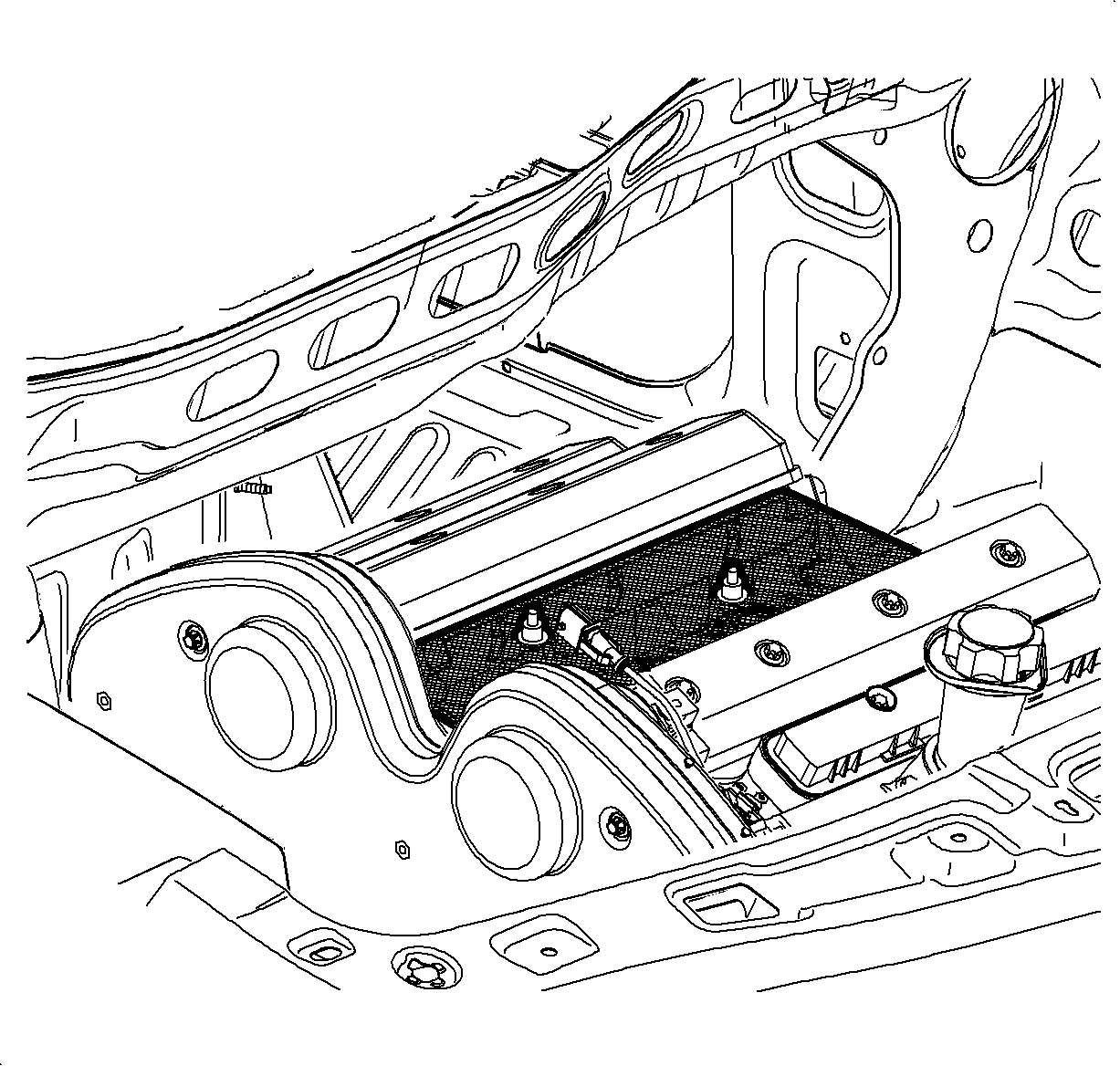
- Remove air cleaner assembly. Refer to "Air Cleaner Assembly Replacement" in the appropriate Service Manual. (For 2004 Saturn L-Series vehicles, refer to SI Document ID #1226088.)
- Remove intake manifold. Refer to "Intake Manifold Replacement" in the appropriate Service Manual. (For 2004 Saturn L-Series vehicles, refer to SI Document ID #1227105.)
- Install debris screen J45482 on intake spacer plate.
- Remove camshaft covers. Refer to "Camshaft Cover Replacement - Front/Rear" in the appropriate Service Manual. (For 2004 Saturn L-Series vehicles, refer to SI Document ID #1052946, 1052971.)
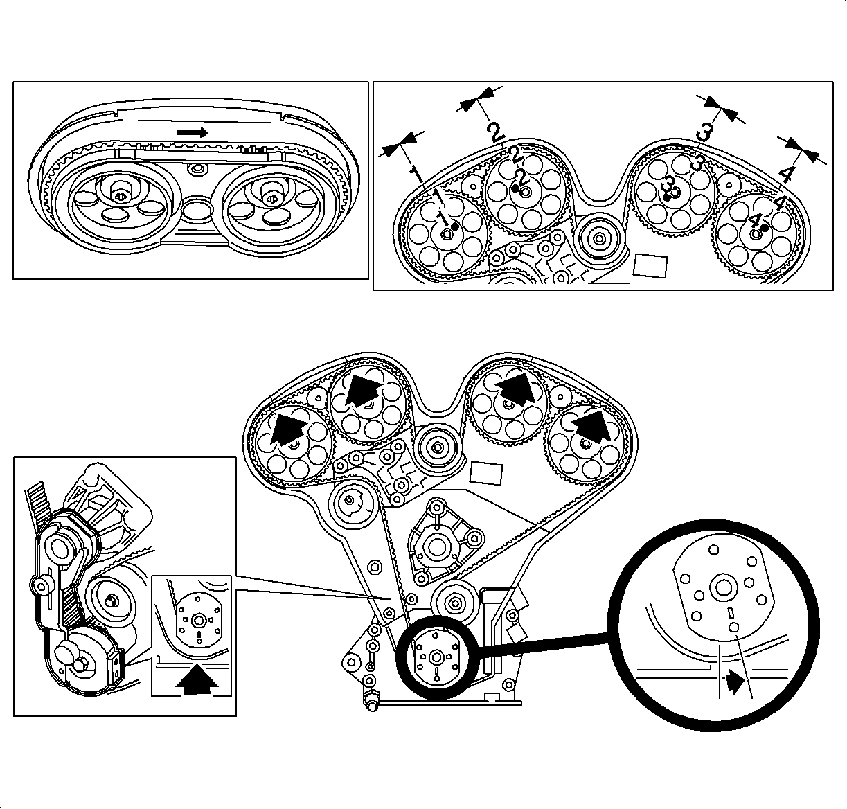
- Remove timing belt. Refer to "Timing Belt Replacement" in the appropriate Service Manual. (For 2004 Saturn L-Series vehicles, refer to SI Document ID #1215992.)
- Remove camshaft drive sprockets. Refer to "Camshaft Drive Sprocket Replacement" in the appropriate Service Manual. (For 2004 Saturn L-Series vehicles, refer to SI Document ID #1053149.)
- Remove camshafts with seal attached. Refer to "Camshaft Replacement - Front/Rear" in the appropriate Service Manual. (For 2004 Saturn L-Series vehicles, refer to SI Document ID #1220003, 1220006.)
- Remove spark plugs.
- Rotate crankshaft to cylinder #1 top dead center (TDC), lock crankshaft with crankshaft locking tool J42069-10 , and secure to water pump to prevent crankshaft rotation when pressurizing combustion chambers.
- Using a magnet, lift and remove the lifters. Place the lifters in rack sequentially so they can be reinstalled in their original order.
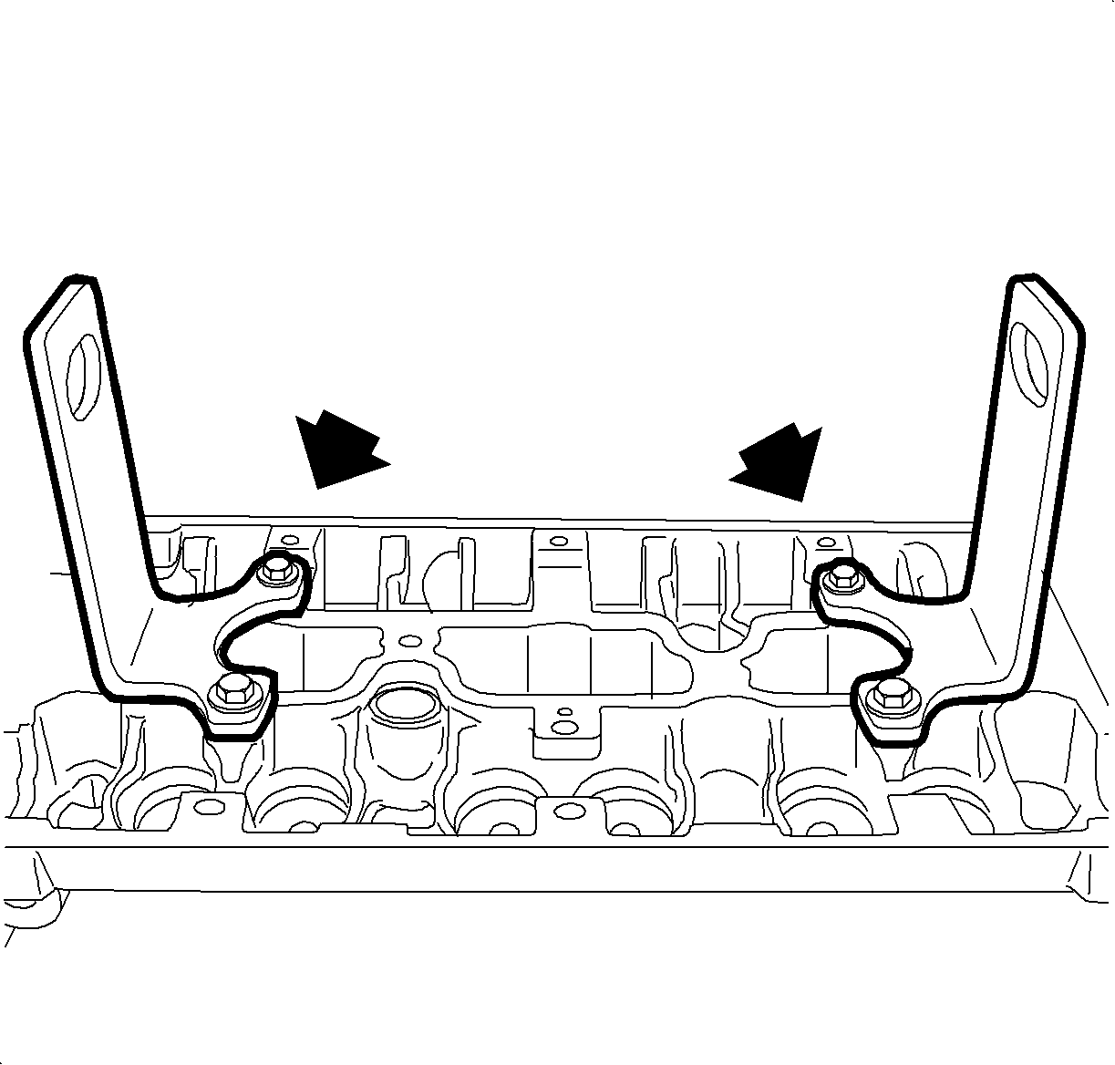
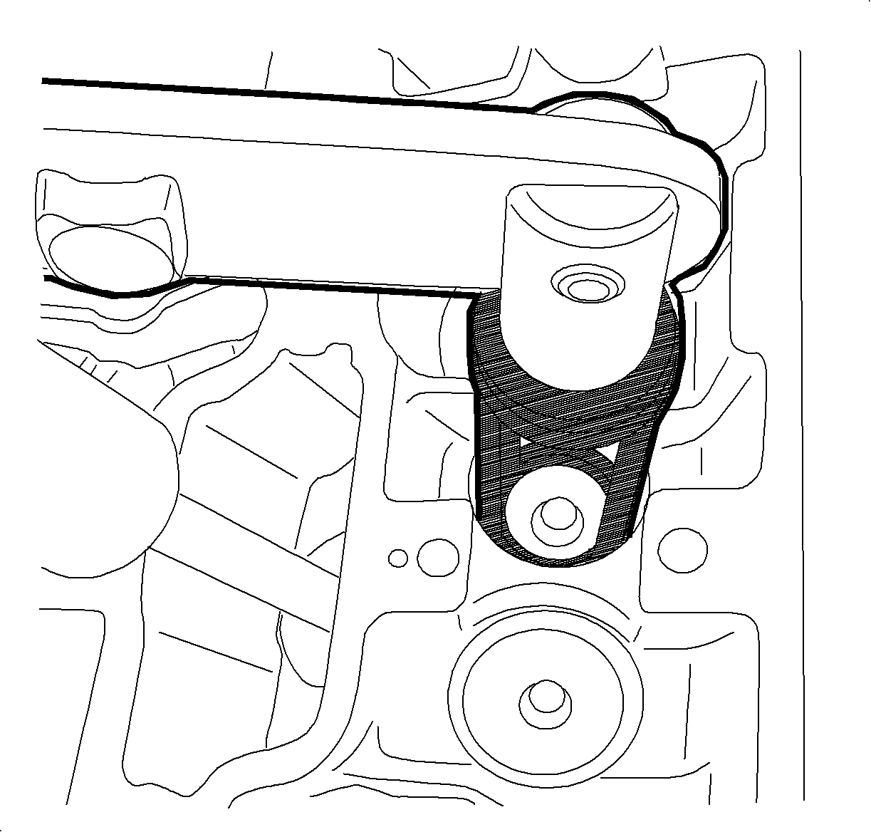
- Install Valve Spring Compressor J43952 (2 each) onto cylinder head using cam cover bolts (4 each) as shown.
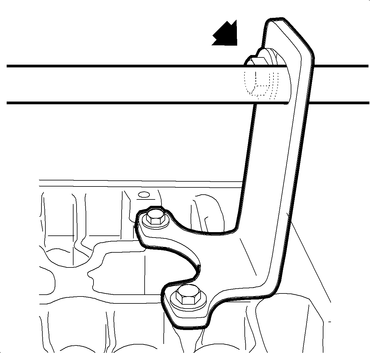
- Install bolt and nut through Valve Spring Compressor J43952 (2 each) and position bolt and nut towards exhaust side of slot in J43952 as shown (rear cylinder head shown).
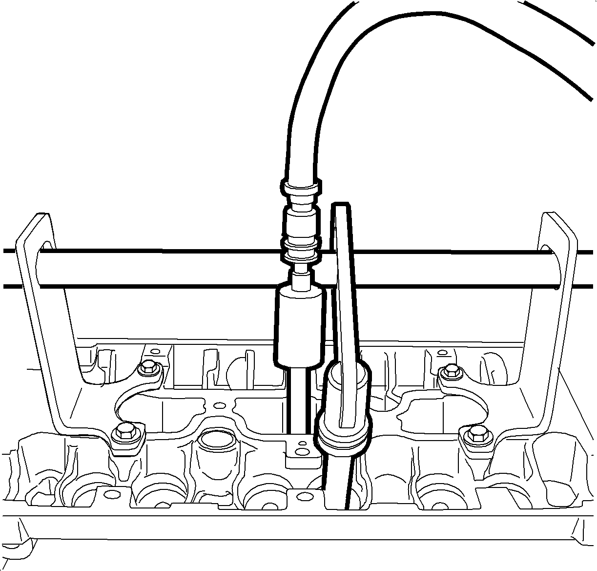
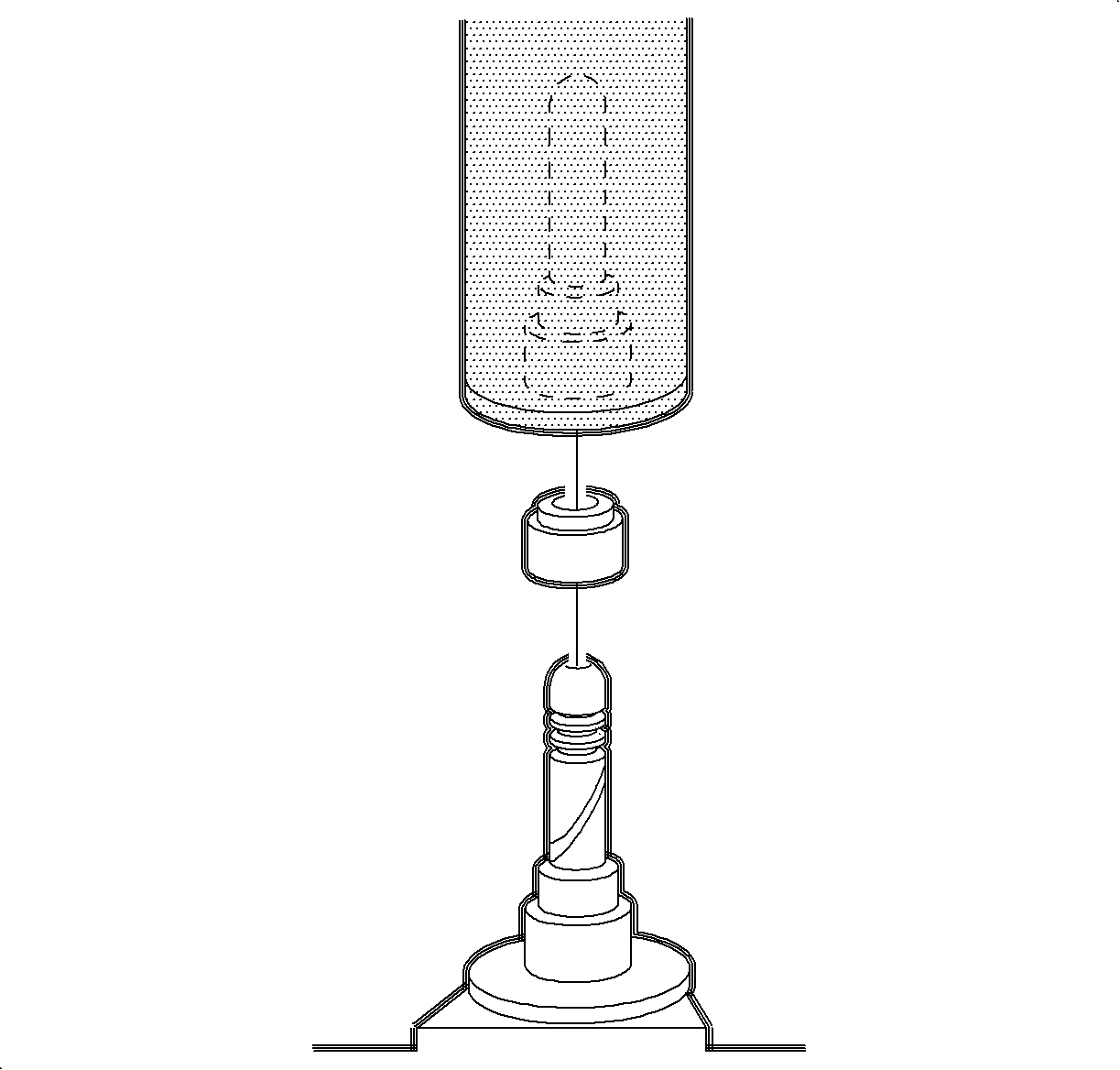
- Install Spark Plug Adapter 309729 from Universal Pressure Test Kit into spark plug port.
- Assemble Universal Pressure Test Kit components: 309726 and 309734 from SA9127E and install on vehicle to pressurize combustion chamber.
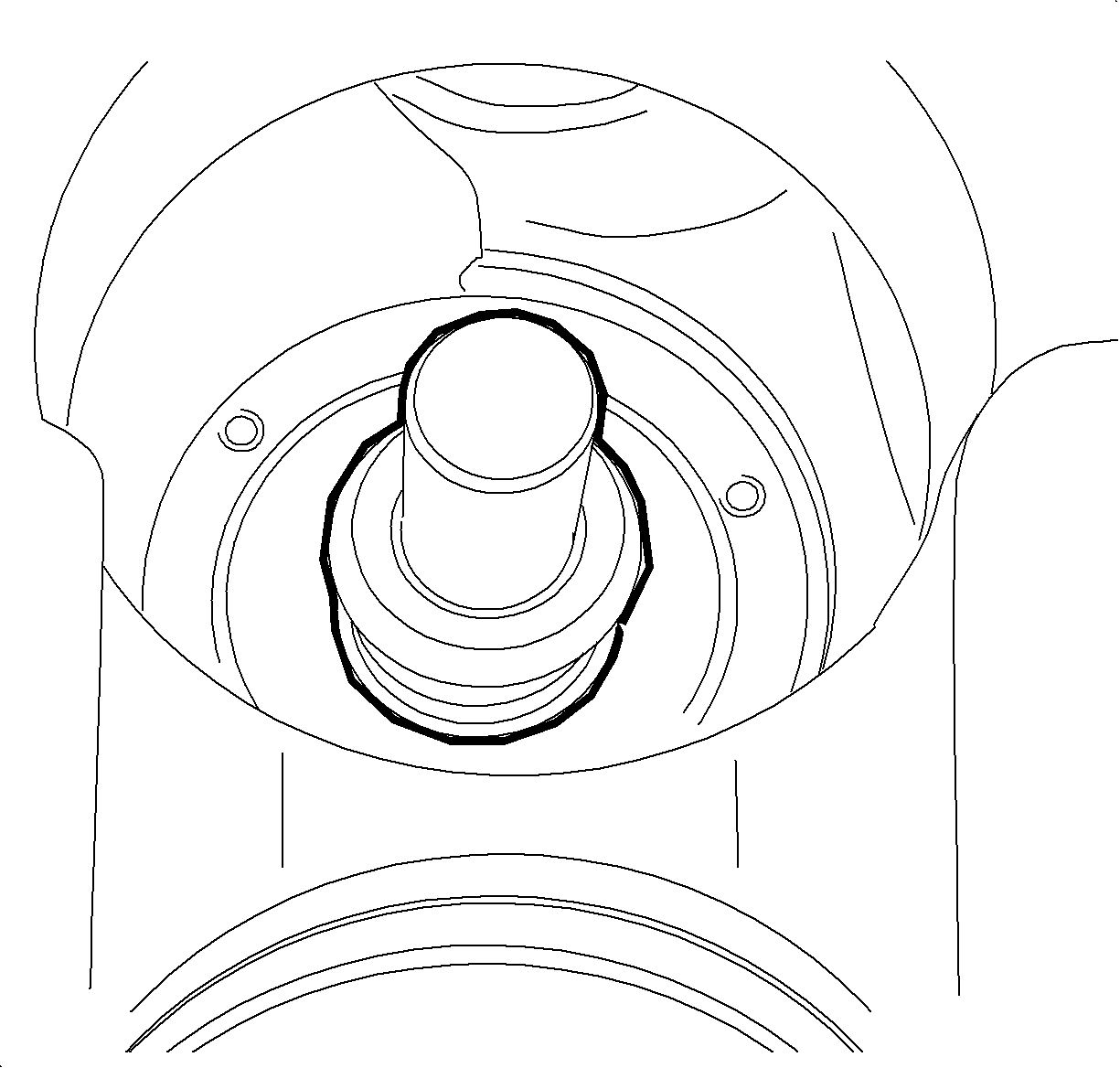
- Use Spring Compressor Arm SA9124E-2 and Pivot Bar SA9124E-4 from Engine Kit SA1991E1 , Case 1 of 1 and Valve Spring Compressor J43963 from 3.0L V-6 Engine Kit J43930 , Case 1 of 2 and install as shown.
- Pressurize combustion chamber to 690 kPa (100 PSI) to prevent valves from dropping during valve spring removal.
- Compress valve spring.
- Remove valve stem keys.
- Remove cap from valve spring.
- Remove valve spring.
- Inspect valve stem oil seal for color.
Caution: When performing service on or near the SIR components or the SIR wiring, the SIR system must be disabled. Refer to SIR Disabling and Enabling Zones. Failure to observe the correct procedure could cause deployment of the SIR components, personal injury, or unnecessary SIR system repairs.
Caution: Before servicing any electrical component, the ignition key must be in the OFF or LOCK position and all electrical loads must be OFF, unless instructed otherwise in these procedures. If a tool or equipment could easily come in contact with a live exposed electrical terminal, also disconnect the negative battery cable. Failure to follow these precautions may cause personal injury and/or damage to the vehicle or its components.
| 1.1. | Record all of the vehicle preset radio stations |
| 1.2. | Turn OFF all the lamps and the accessories. |
| 1.3. | Make sure the ignition switch is in the OFF position. |
| 1.4. | Disconnect the battery negative cable from the battery. |
Notice: As a precaution, rotate the crankshaft counterclockwise to 60° before top dead center (BTDC) position to prevent valve/piston contact when removing timing belt. Failure to do this may result in damage to the valves and/or pistons.
Caution: Wear safety glasses when using compressed air in order to prevent eye injury.
Notice: When compressing valve spring, ensure Valve Spring Compressor J43963 does not damage lifter bore. Step 13 positions Pivot Bar SA9124E-4 towards intake side of slot in Valve Spring Compressor J43952 which aids in compressing valve spring.
| • | If valve stem oil seal is brown, perform Procedures A and C. |
| • | If valve stem oil seal is green, perform Procedures B and C. |
Procedure A
- Remove valve stem oil seal using Valve Stem Oil Seal Remover SA9102E-A from Engine Kit SA1991E1 , Case 1 of 1.
- Install new valve stem oil seals (green), P/N 90410741, using Valve Stem Oil Seal Installer J41775 from 3.0L V-6 Engine Kit J43930, Case 1 of 2.
- Install valve spring.
- Install cap on valve spring.
- Compress valve spring and install valve stem keys.
- Repeat procedure on remaining valves.
Important: Perform Procedure A only if valve stem oil seal is brown.

Notice: When compressing valve spring, ensure Valve Spring Compressor J43963 does not damage lifter bore. Step 13 positions Pivot Bar SA9124E-4 towards intake side of slot in Valve Spring Compressor J43952 which aids in compressing valve spring.
Procedure B
- Install valve spring.
- Install cap on valve spring.
- Compress valve spring and install valve stem keys.
- Contact the Saturn Technical Assistance Center (USA: 1-800-828-2112, prompt 1; Canada: English 1-800-263-7740 or French 1-800-263-7960) for the latest direction for repairing blue smoke on startup.
Important: Perform Procedure B only if valve stem oil seal is green.
Notice: When compressing valve spring, ensure Valve Spring Compressor J43963 does not damage lifter bore. Step 13 positions Pivot Bar SA9124E-4 towards intake side of slot in Valve Spring Compressor J43952 which aids in compressing valve spring.
Procedure C
- Re-install lifters in original location.
- Unlock crankshaft from water pump and rotate to 60° before top dead center (BTDC).
- Install camshafts with seals attached. Refer to "Camshaft Replacement - Front/Rear" in the appropriate Service Manual. (For 2004 Saturn L-Series vehicles, refer to SI Document ID #1220003, 1220006.)
- Install camshaft drive sprockets in proper orientation using new bolts. Refer to "Camshaft Drive Sprocket Replacement" in the appropriate Service Manual. (For 2004 Saturn L-Series vehicles, refer to SI Document ID #1053149.)
- Install timing belt. Refer to "Timing Belt Replacement" in the appropriate Service Manual. (For 2004 Saturn L-Series vehicles, refer to SI Document ID #1215992.)
- Install spark plugs.
- Install camshaft covers. Refer to "Camshaft Cover Replacement - Front/Rear" in the appropriate Service Manual. (For 2004 Saturn L-Series vehicles, refer to SI Document ID #1052946, 1052971.)
- Remove debris screen J45482 from intake spacer plate.
- Install intake manifold. Refer to "Intake Manifold Replacement" in the appropriate Service Manual. (For 2004 Saturn L-Series vehicles, refer to SI Document ID #1227105.)
- Install air cleaner assembly. Refer to "Air Cleaner Assembly Replacement" in the appropriate Service Manual. (For 2004 Saturn L-Series vehicles, refer to SI Document ID #1226088.)
- Connect negative battery cable.
- Verify that blue smoke condition has been resolved. Start vehicle and verify that there is no blue smoke coming from exhaust.
Important: Perform Procedure C on all engines (any valve stem oil seal color).
Notice: Use the correct fastener in the correct location. Replacement fasteners must be the correct part number for that application. Fasteners requiring replacement or fasteners requiring the use of thread locking compound or sealant are identified in the service procedure. Do not use paints, lubricants, or corrosion inhibitors on fasteners or fastener joint surfaces unless specified. These coatings affect fastener torque and joint clamping force and may damage the fastener. Use the correct tightening sequence and specifications when installing fasteners in order to avoid damage to parts and systems.
Important: For 2003 Saturn L-Series vehicles, check engine serial number to identify the correct procedure for timing belt replacement.
Tighten
Tighten spark plugs to 25N·m(18 ft-lb).
| Important: Clean any existing oxidation from the contact face of the battery terminal and battery cable using a wire brush before installing the battery cable to the battery terminal. |
| 11.1. | Connect the negative battery cable to the battery. |
Tighten
Tighten the negative battery cable bolt to 17N·m(13 ft-lb).
| 11.2. | Reset the radio stations and the clock. |
Parts Information
Part Number | Description | Qty |
|---|---|---|
90410741 | Seal Assembly - Valve Stem Oil | 1 pkg of 24 seals |
90466737 | Bolt/Screw - Cam Shaft Sprocket Rear | 2 |
90573287 | Bolt/Screw - Cam Shaft Sprocket Front | 2 |
Claim Information
To receive credit for this repair during the warranty coverage period, submit a claim through the Saturn Dealer System for any of the following, depending on the procedure performed:
| • | J0540 Spring, Cap and/or Seal, Valve - Replace One Cyl, Right (Rear) Bank |
| • | J0541 Spring, Cap and/or Seal, Valve - Replace One Cyl, Left (Front) Bank |
| • | J0547 Spring, Cap and/or Seal, Valve - Replace One Cyl, Both Banks |
