Intake Runner Replacement Front
Tools Required
J 43914 Universal Clamp Pliers
Removal Procedure
- Disconnect the negative battery cable.
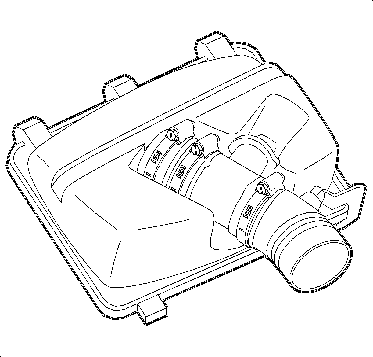
- Remove the intake hose assembly.
- Remove 4 rubber boot hose clamps using the J 43914 .
- Remove the intake runner mounting bolts.
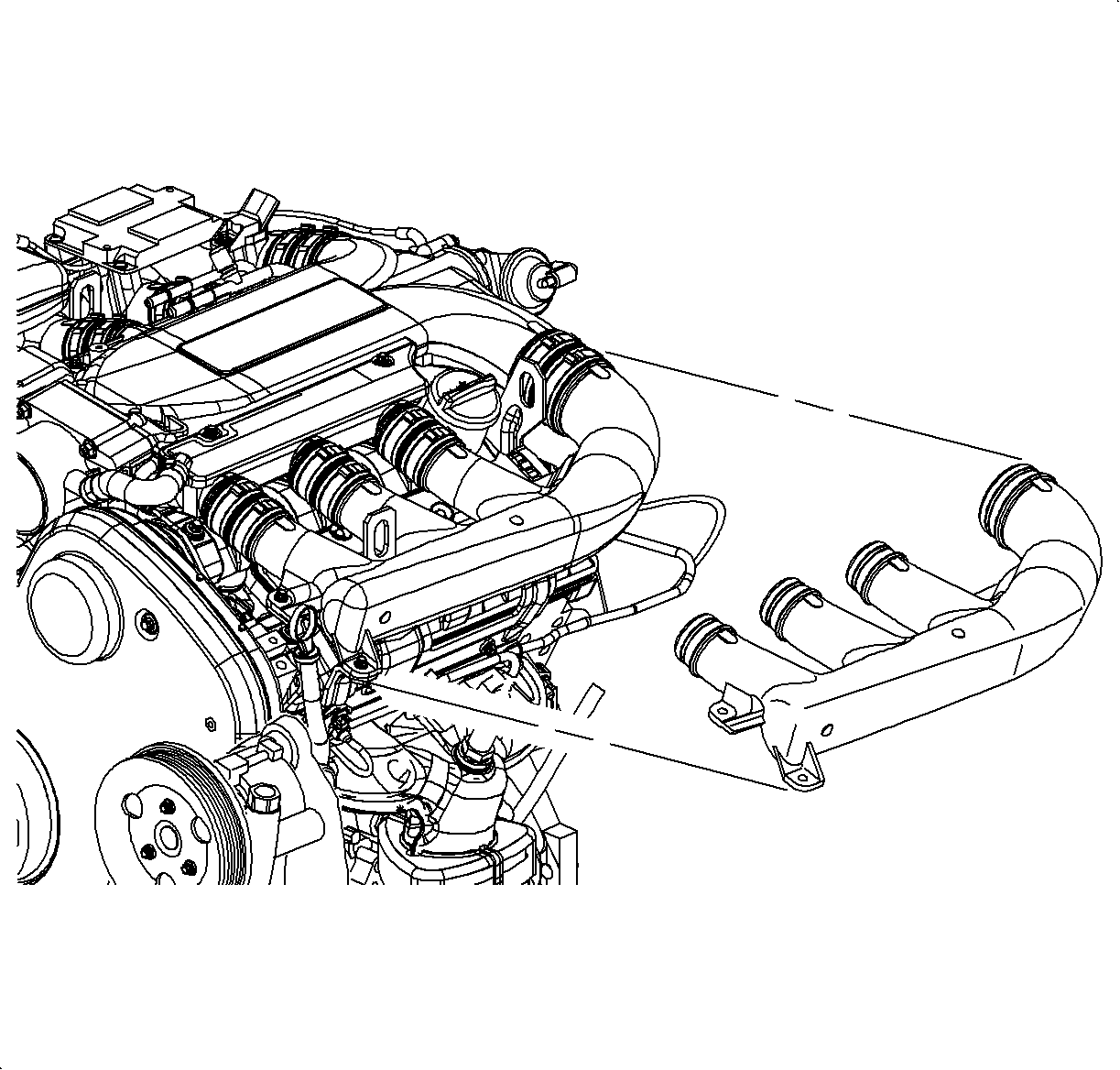
- Disconnect the intake runner from the rubber boots and remove the intake runner.
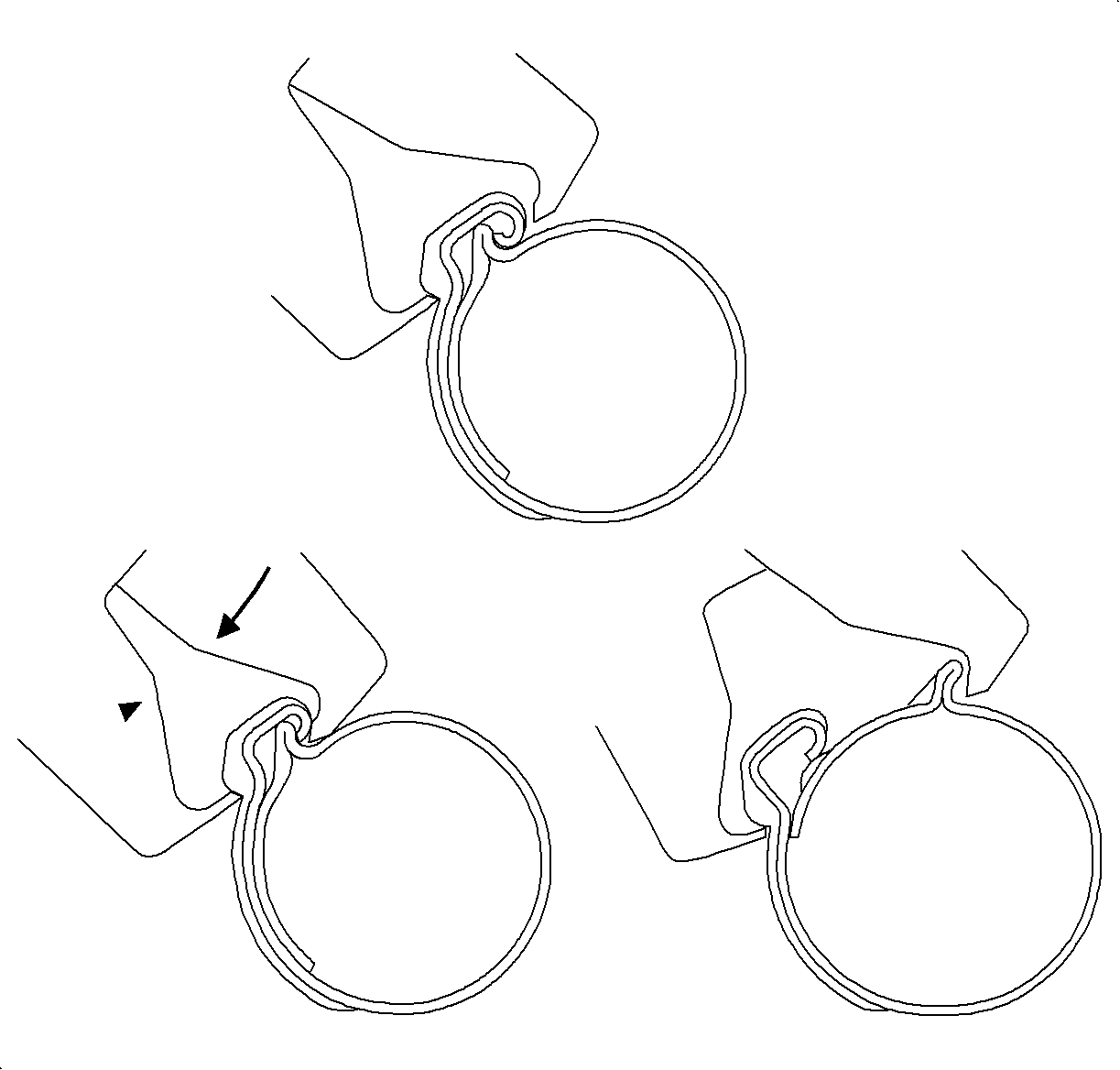
Important: Clamps are reusable if not damaged. Do not discard.
Installation Procedure
- Install the intake runner onto the rubber boots.
- Install the intake runner mounting bolts.
- Install the 4 rubber boot hose clamps using the J 43914 .
- Install the hose assembly.
- Connect the negative battery cable.

Notice: Refer to Fastener Notice in the Preface section.
Tighten
Tighten the intake manifold runner bolts to 8 N·m
(71 lb in).
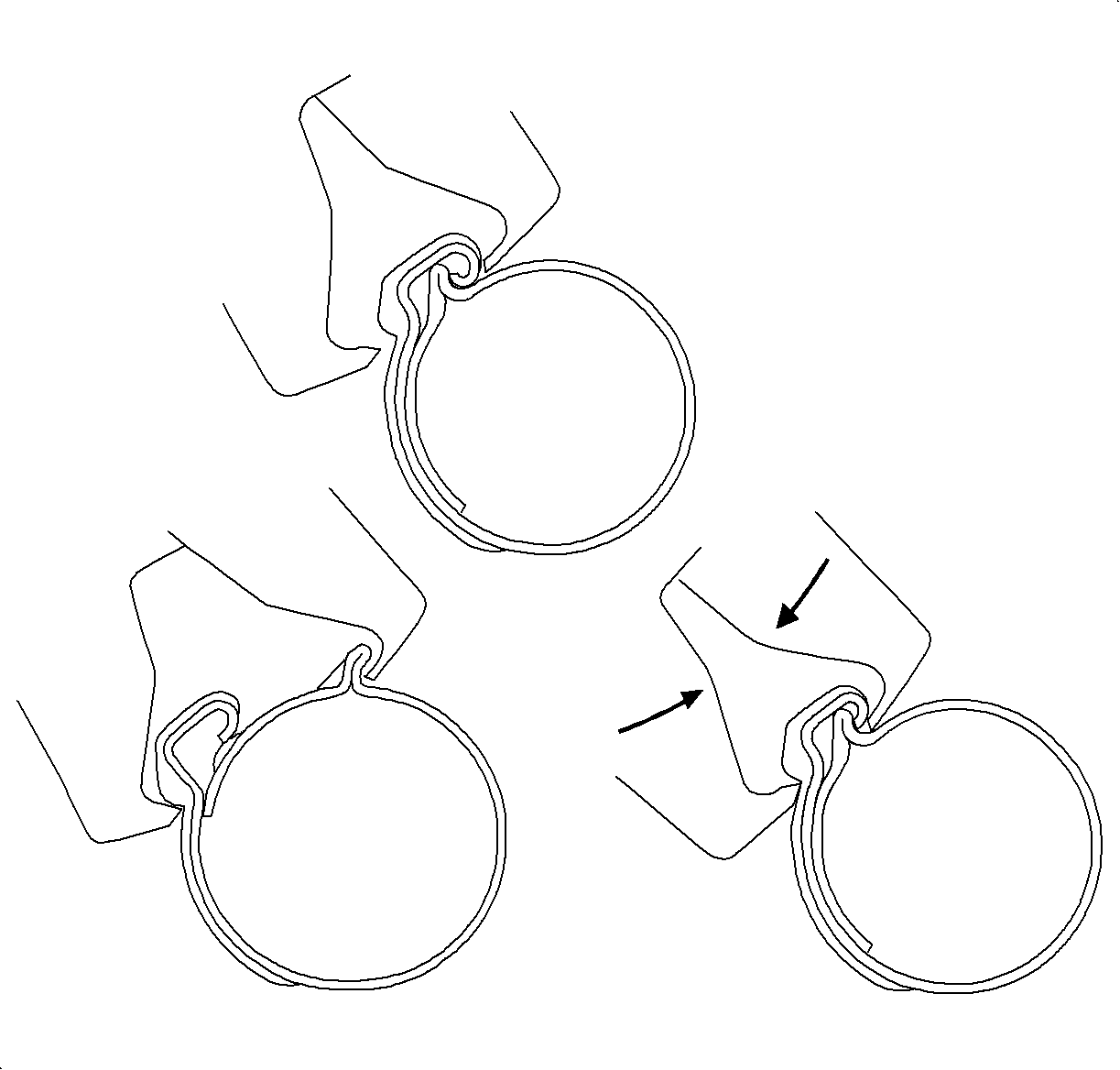
Important: Inspect the hose clamps for damage. Replace if damaged.

Tighten
Tighten the battery terminal bolts to 17 N·m
(13 lb ft).
Intake Runner Replacement Rear
Tools Required
J 43914 Universal Clamp Pliers
Removal Procedure
- Disconnect the negative battery cable.
- Remove the intake hose assembly.
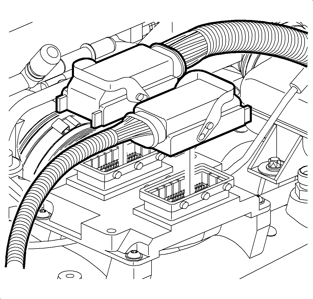
- Remove the ECM electrical connectors.
- Remove the ECM bolts and the ECM.
- Remove the 4 rubber boot hose clamps using the J 43914 .
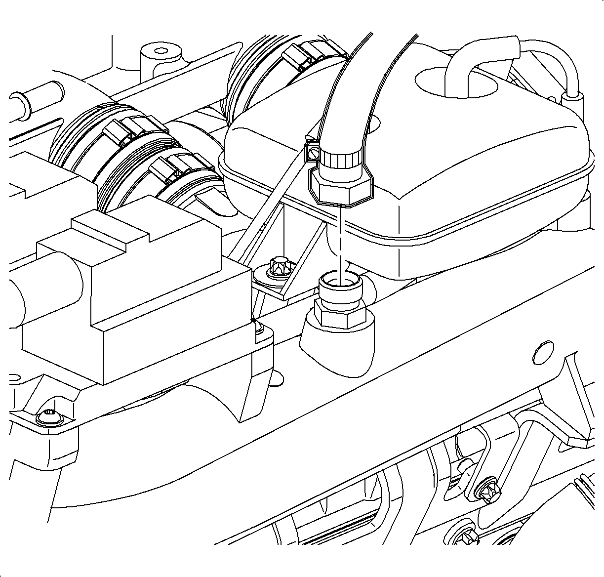
- Disconnect the threaded brake vacuum hose.
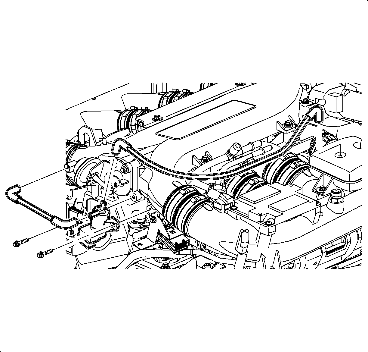
- Disconnect the intake plenum switch-over valve vacuum hose at the switch-over valve. Note the hose routing.
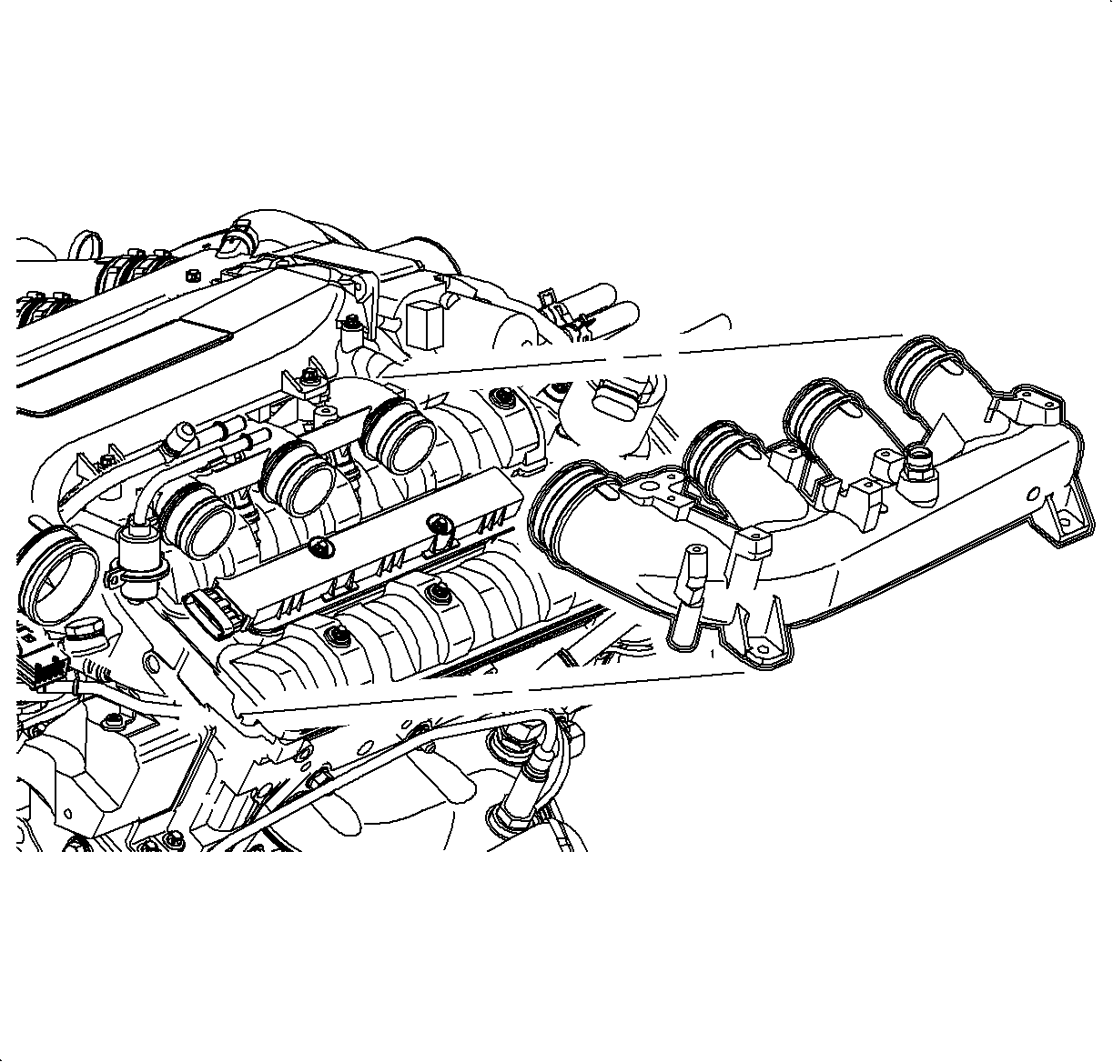
- Remove the intake runner mounting bolts.
- Disconnect the vent hose from the throttle body.
- Disconnect the intake runner from the rubber boots and remove the intake runner. Note the throttle body vent hose routing.


Important: Clamps are reusable if not damaged. Do not discard.
Installation Procedure
- Install the intake runner onto the rubber boots.
- Route the throttle body vent hose under the vacuum reservoir and connect to the throttle body.
- Install the intake runner mounting bolts.
- Route the intake plenum switch-over valve vacuum hose and connect to the switch-over valve.
- Connect the threaded brake vacuum line.
- Install the 4 rubber boot hose clamps using the J 43914 .
- Install the ECM and ECM bolts.
- Connect the ECM electrical connectors.
- Install the intake hose assembly.
- Connect the negative battery cable.

Notice: Refer to Fastener Notice in the Preface section.
Tighten
Tighten the intake manifold runner bolts to 8 N·m
(71 lb in).


Tighten
Tighten the brake vacuum line to 20 N·m
(15 lb ft).

Important: Inspect the hose clamps for damage. Replace if damaged.

Tighten
Tighten the engine control module bolts to 8 N·m
(71 lb in).

Tighten
Tighten the battery terminal bolts to 17 N·m
(13 lb ft).
