GM Service Manual Online
For 1990-2009 cars only

Removal Procedure


    Object Number: 896483  Size: SH
  1. Remove the battery.
  2. Remove the intake air cleaner. Air Cleaner Assembly Replacement
  3. Disconnect the MAF connector.
  4. Remove the battery ground cable at the wheel housing.
  5. Remove the positive main feed cable at the fuse block.
  6. Disconnect the TCM main connector under the cowl cover and secure to the engine.
  7. Disconnect the TCM inline connector located near the brake master cylinder.
  8. Disconnect the A/C pressure connector.
  9. Remove the fuse block.
  10. 9.1. Remove the fuse block cover.
    9.2. Disconnect the BLACK engine harness connector under the fuse block panel.
    9.3. Remove the lower weather-pack connector inside the fuse block.
    9.4. Secure the engine harness to the top of the engine.
    9.5. Remove the fuse block mounting bolts.
    9.6. Remove the fuse block and secure away from the engine.
  11. Remove the battery tray.
  12. Disconnect the EVAP purge connector.
  13. Disconnect the right front speed sensor connector and secure to the top of the engine.
  14. Disconnect the front O2 sensor from down pipe.
  15. Disconnect the following electrical connections:
  16. 14.1. The tansaxle ground
    14.2. The transaxle main connector
    14.3. The transaxle shift control
    14.4. The rear connector on ECM
  17. Remove the brake booster vacuum hose.
  18. Relieve the fuel pressure.
  19. Disconnect the fuel lines and secure away from the engine.
  20. Disconnect the EVAP purge hose at the EVAP purge solenoid.
  21. Raise the vehicle.
  22. Remove the starter.
  23. Remove the torque converter bolts.
  24. Drop the exhaust system from the catalytic converter forward.
  25. Disconnect the transaxle nose bracket.
  26. Remove the A/C compressor mounting bolts and secure to the frame rail.
  27. Drain the engine coolant.
  28. Disconnect the heater hoses at the lower cowl.
  29. Disconnect the lower engine to transaxle bell housing bolts. Do not remove the upper bolts at this time.
  30. Lower the vehicle.
  31. Remove the main hose to the coolant reservoir from the engine inlet adapter.
  32. Remove the lower radiator hose from the engine.
  33. Remove the upper radiator hose from the engine.
  34. Drain the power steering fluid by removing the small hose from under the reservoir.
  35. Disconnect the metal power steering line.
  36. Disconnect the power steering reservoir from the radiator support and secure to the top of the engine.
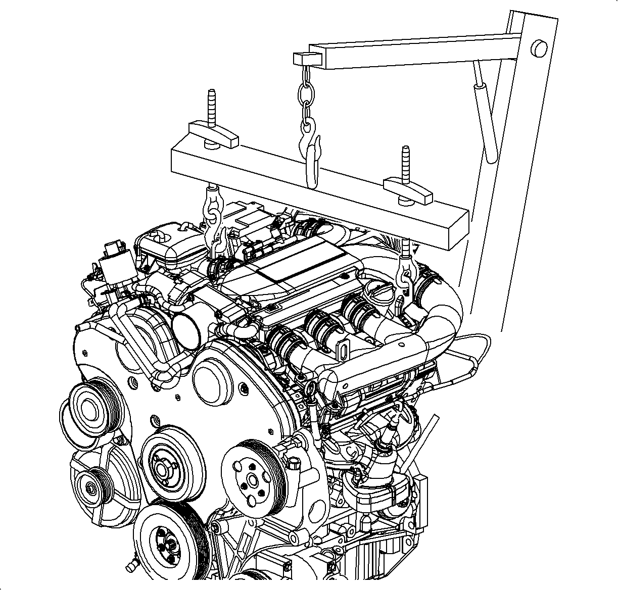
  37. Attach the engine lift hoist to the lift hooks on the engine and support the engine weight.
  38. Remove the right front engine mount from the wheel housing.
  39. Remove the engine mount bracket from the engine.
  40. Remove the upper bell housing bolts.
  41. Lift the engine out of the vehicle.

Installation Procedure


    Object Number: 896483  Size: SH
  1. Lower the engine into the vehicle and guide it to mate with the dowel pins on the transaxle.
  2. When the engine and the transaxle are aligned on the shuffle pins, install the upper bell housing bolts. Do not torque at this time.
  3. Notice: Refer to Fastener Notice in the Preface section.

  4. Install the engine mount bracket onto the engine and install the bolts.
  5. Tighten
    Tighten the engine mount bracket bolts to 55 N·m (41 lb ft).

  6. Install the right front engine mount and install the bolts.
  7. Tighten
    Tighten the engine mount-to-frame bolts to 55 N·m (41 lb ft).

  8. Install the transaxle nose bracket bolts.
  9. Tighten
    Tighten the nose cone bracket-to-oil pan bolts (transaxle nose bracket bolts) to 40 N·m (30 lb ft).

  10. Remove the engine lift hoist.
  11. Attach the metal power steering line.
  12. Attach the small hose to the bottom of the power steering reservoir.
  13. Attach the power steering reservoir to the radiator support.
  14. Install the upper radiator hose.
  15. Install the lower radiator hose
  16. Attach the main coolant reservoir hose to the engine.
  17. Raise the vehicle.
  18. Install the lower engine to the transaxle bell housing bolts and torque.
  19. Tighten
    Tighten the lower engine-to-transaxle bell housing bolts to 65 N·m (48 lb ft).

  20. Install the torque converter bolts.
  21. Tighten
    Tighten the torque converter bolts to 65 N·m (48  lb ft).

  22. Install the starter.
  23. Connect the heater hoses at the lower cowl.
  24. Install the A/C compressor to the engine mounting bracket.
  25. Tighten
    Tighten the A/C compressor bracket bolts to 40 N·m (30 lb ft).

  26. Install the exhaust down pipes to the catalytic converter.
  27. Lower the vehicle.
  28. Connect the EVAP purge solenoid hose.
  29. Connect the fuel lines.
  30. Connect the brake booster vacuum hose.
  31. Connect the following electrical connections:
  32. 24.1. The rear connector on the ECM
    24.2. The transaxle shift control
    24.3. The transaxle main connector
    24.4. The transaxle ground
    24.5. The right front speed sensor
  33. Connect the front O2 sensor connector.
  34. Connect the right front speed sensor.
  35. Connect the EVAP purge solenoid connector.
  36. Torque the upper bell housing bolts.
  37. Tighten
    Tighten the upper bell housing bolts to 65 N·m (48 lb ft).

  38. Install the battery tray.
  39. Install the fuse block.
  40. 30.1. Install the fuse block mounting bolts.
    30.2. Route the engine harness into the block.
    30.3. Connect the lower weather pack connector.
    30.4. Connect the main engine harness under the fuse block panel.
    30.5. Assemble the fuse block.
  41. Connect the A/C pressure connector.
  42. Connect the TCM inline connector near the brake master cylinder.
  43. Connect the TCM main connector under the cowl cover and secure it to the engine.
  44. Connect the positive main feed cable at the fuse block.
  45. Connect the battery ground cable at the wheel housing.
  46. Install the battery.
  47. Install the intake air cleaner. Air Cleaner Assembly Replacement
  48. Connect the MAF connector.
  49. Add coolant.
  50. Add power steering fluid.
  51. Start the engine and check for leaks.