Fuel Cap
The fuel cap seals the inlet end of the fuel filler pipe and prevents the escape of fuel liquid and vapor. It is tethered to the fuel door on the vehicle body to prevent loss. The cap requires 1/4 turn, plus an additional 1/4 turn to activate at least 3 clicks of the ratcheting top feature, to engage the filler pipe neck during installation.
The cap also incorporates a spring-loaded, free-spin feature (about 150 degrees) noted during removal.
The cap is vented to the atmosphere in both positive and negative (vacuum) pressure modes to prevent build-up of excessive pressure in the system.
The cap is designed to vent at a positive pressure of about 2 psi (56 in H2O and negative pressure (vacuum) of about 1 psi (28 in H2O).
Fuel Filler Pipe
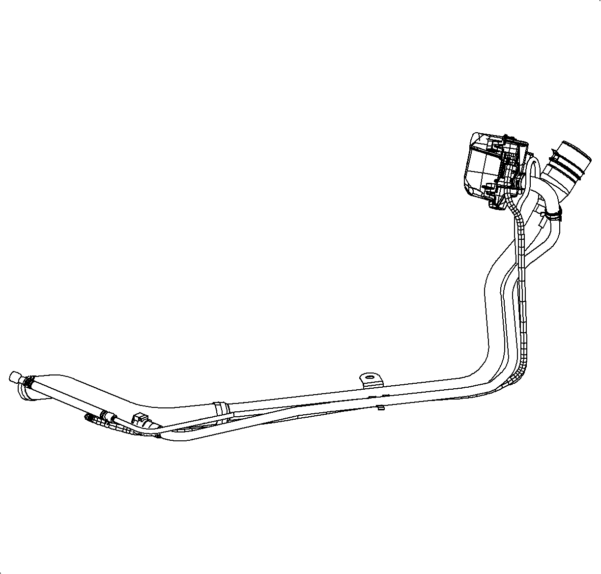
The fuel filler pipe consists of a fuel delivery tube, vapor recirculating line, and a separate vent pipe. The recirculating line is used to carry fuel vapor and control their entry back into the fuel tank during the refueling process. The vent line is used to vent air, after the fuel vapors have been captured by the EVAP canister, from the fuel tank during refueling or during thermal expansion of the vapor in the fuel tank.
Fuel Fill Check Valve
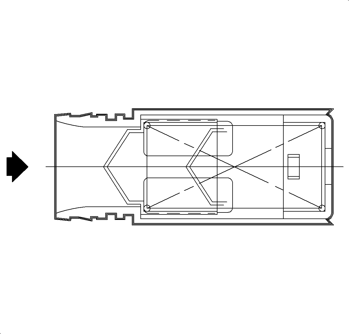
The fuel fill check valve is plastic welded into the fuel tank inlet. This one-way check valve prevents liquid fuel from rushing back up the tube when the fuel delivery is stopped. It also aids in controlling the fuel tank vapors from traveling back up the filler tube. It is not serviceable. If defective, the fuel tank assembly must be replaced.
Fuel Filter
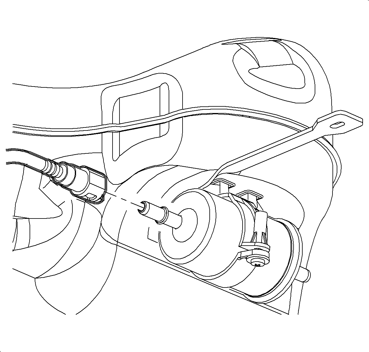
Fuel filters fall into the following 2 categories:
| • | In-line filters |
| • | Sending unit filter socks |
In-Line Filters
The in-line filter can be found in the fuel feed line under the vehicle and mounted on the passenger's side in the front of the wheel house.
In-Tank Fuel Filters
The woven plastic filter is located on the lower end of the fuel pickup tub in the fuel tank. This filter prevents dirt from entering the fuel line and also stops water, unless the filter becomes completely submerged in water. This filter is self-cleaning and normally requires no maintenance. Fuel stoppage at this point indicates that the fuel tank contains an abnormal amount of sediment or water. The tank should therefore be thoroughly cleaned.
Fuel Line
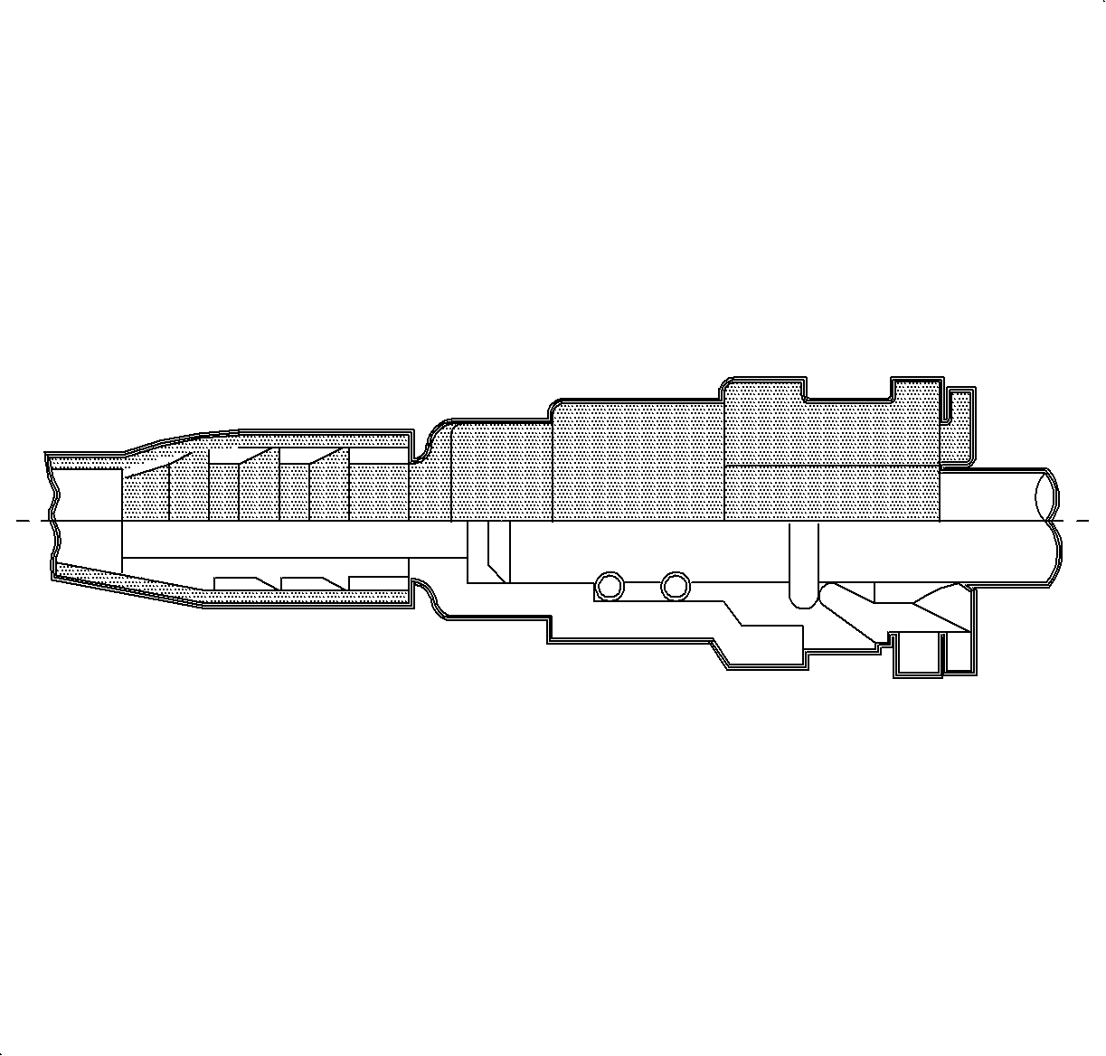
The fuel line, and EVAP canister purge line, is a multi-layer nylon tube covered with a protective, extruded sheath and molded to the correct routing configuration. The lines are mounted to the underbody and trunk with polymer clips and secured with plastic screws.
The fuel and EVAP lines are not repairable, neither are their connector bodies. They must be serviced as a unit if they leak, are damaged, kinked, or crimped.
The connector quick connect retainers are not reusable and must be replaced after disconnecting the connectors.
Important: The connector quick connect retainers are not interchangeable between 1.9L (L24, LL0), 2.2L (L61), or 3.0L (L81). When replacing the retainers, ensure that the correct retainers are used.
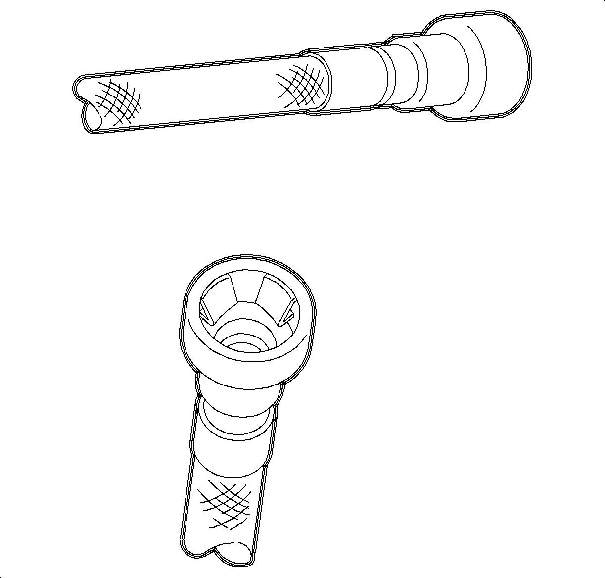
The front fuel lines use a different type of fuel line connection at the fuel rail. To separate these lines, the J 37088-A expansion tool is required.
Fuel Rail Assembly - L81
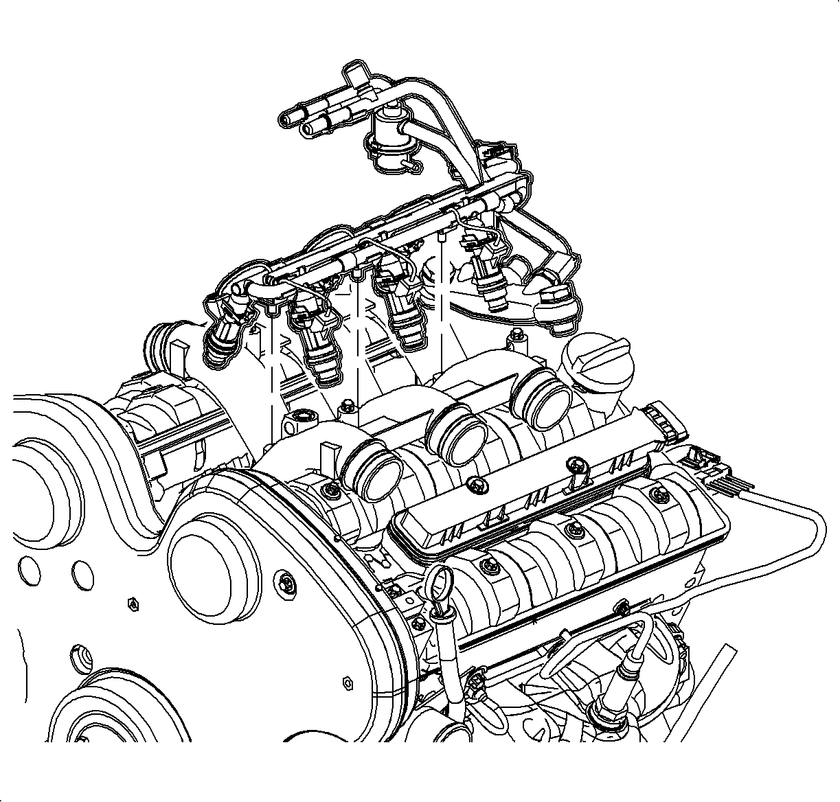
The fuel rail assemblies are mounted in the intake manifold and performs several functions. It positions the fuel injectors in the intake manifold, and distributes fuel evenly to the fuel injectors, and dampens fuel pump pressure pulsations. Whenever performing any service on the fuel injectors, it is essential to re-attach the fuel injectors to the fuel rail, using an injector retaining clip, prior to installing the injectors into the intake manifold.
Fuel Injector
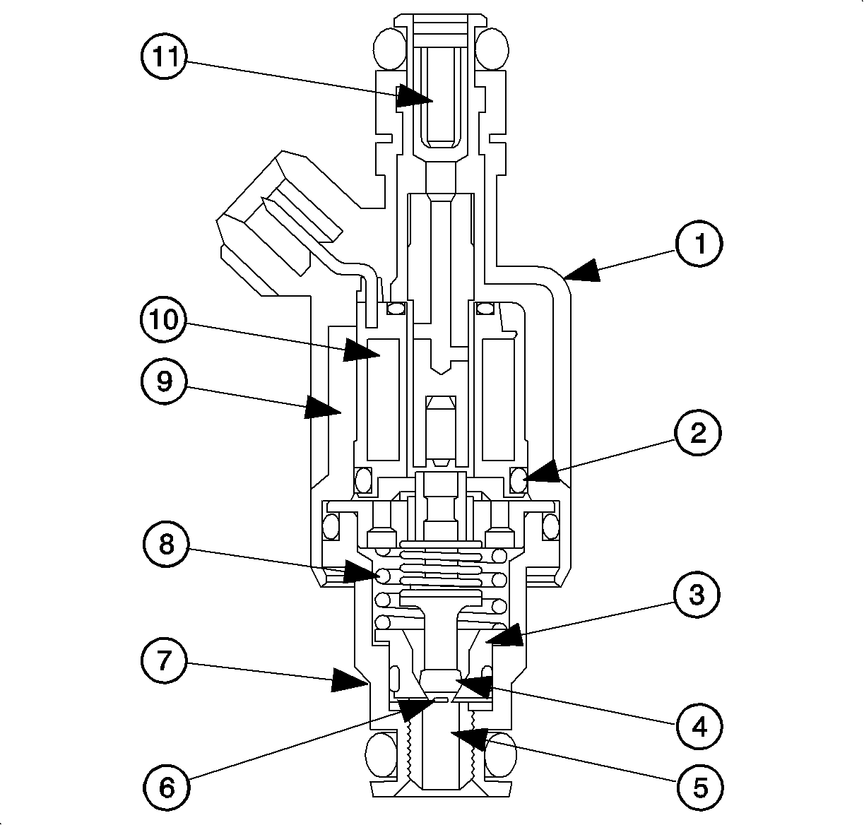
| • | (1) Solenoid Filter |
| • | (2) Spacer and Guide |
| • | (3) Core Seat |
| • | (4) Ball Valve |
| • | (5) Spray Tip |
| • | (6) Director Plane |
| • | (7) Spray Housing |
| • | (8) Core Spring |
| • | (9) Solenoid Housing |
| • | (10) Solenoid |
| • | (11) Fuel Inlet Filter |
The fuel injector assembly is a solenoid operated device, controlled by the PCM, that meters pressurized fuel to a single engine cylinder. The PCM energizes the (12 ohms) solenoid to open a normally closed ball valve. This allows fuel to flow into the top of the fuel injector, past the ball valve, and through a recessed flow director plate at the injector outlet. The director plate has machined holes that control the fuel spray, generating a conical spray pattern of finely atomized fuel at the valve, causing it to become further atomized and vaporized before entering the combustion chamber.
A fuel injector that is stuck partly open or leaking would cause a loss of fuel pressure after engine shut down, so long crank times would be noticed on some engines. Dieseling also could occur because some fuel could be delivered to the engine after the ignition is turned to the OFF position.
All Saturn fuel injectors are designed for a specific engine. They are not interchangeable between each engine option. When servicing the fuel injectors, ensure that the correct injector is used for the specific engine.
Fuel Tank
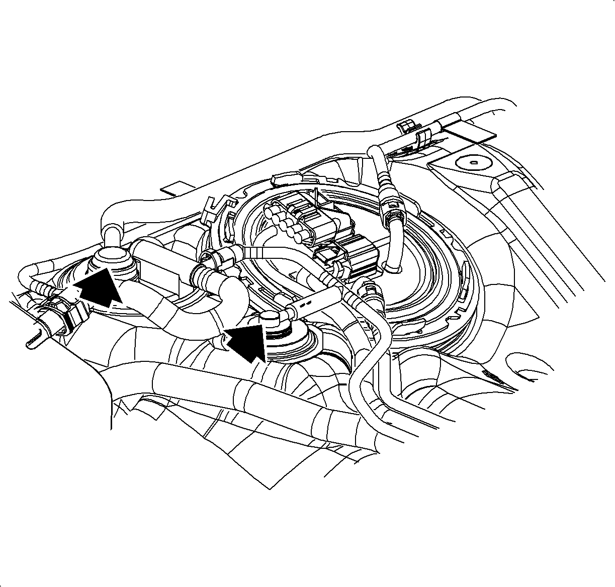
The fuel tank is blow-molded of high-density polyethylene. This material is multi-layer in construction to enhance its ability to minimize leakage of fuel vapors to the atmosphere (impermeability). It is generally 4-5 mm (101.6-127 in) in thickness and incorporates 2 valves which operate during the refueling process.
The fill limit vent valve (FLVV) and grade vent valve are molded into the fuel tank shell and are not serviceable.
| • | Fill limit vent valve (FLVV) -- Located on the top, front surface of the fuel tank, next to the fuel pump module. This is a buoyant float type valve which controls the flow of fuel vapor into the EVAP canister during refueling. The operation of the valve controls fuel tank capacity during the refueling process. Refer to Theory of Operation-ORVR. The valve also prevents liquid fuel from escaping if the vehicle is involved in a roll-over accident. |
| • | Grade vent valve -- Located just rear of the FLVV. This valve's primary function is to provide a vent path for fuel vapors when the tank is full. It also prevents liquid fuel from escaping the fuel tank if (1) the vehicle is operated or parked on an incline, or (2) the vehicle is involved in a roll-over accident. |
Fuel Pump Module
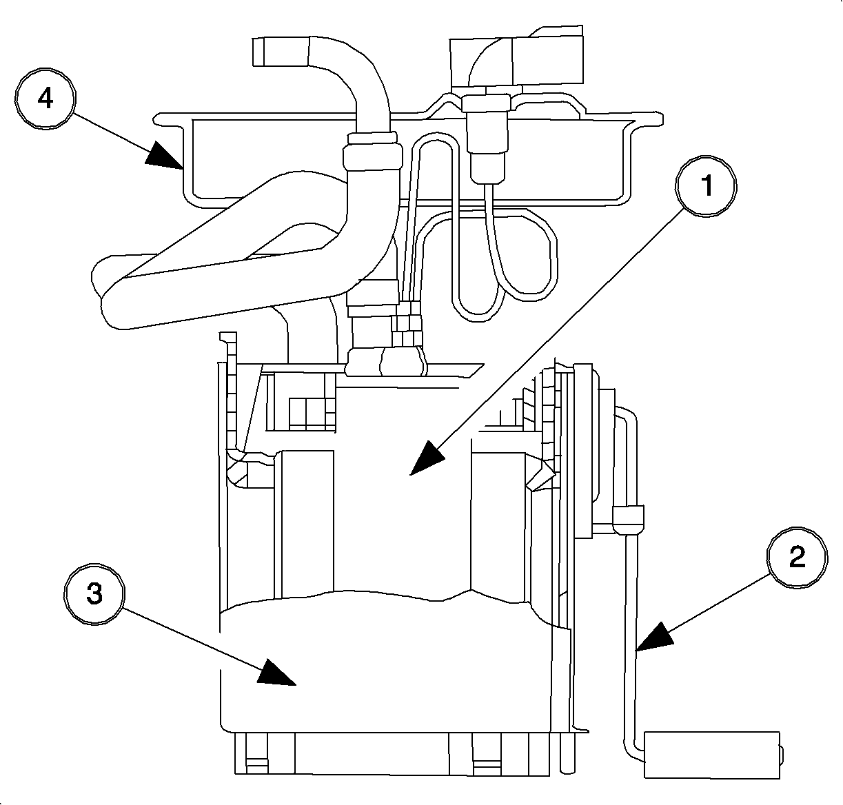
The fuel pump module is sealed to the fuel tank with a retaining ring and O-ring seal. The module consists of:
| • | Fuel pump (1) |
| • | Fuel level sender (2) |
| • | Fuel pump housing (3) |
| • | Fuel pump cover (4) |
Fuel Pump
The fuel pump is a single stage, turbine style, 12 volt unit controlled by the PCM. The PCM supplies a 12 volt feed to a relay in the left instrument panel fuse block (LIPFB). This relay controls a 12 volt supply to the fuel pump.
The fuel pump will only operate with the ignition ON and the engine running or cranking. With the ignition ON, the pump relay is only energized for 2-3 seconds and will be disabled if the PCM does not see reference pulses from the EI module. To re-initialize the pump, the ignition must be turned OFF for at least 10 seconds.
The pump is capable of delivering over 2 liters (0.528 gallons) of fuel per minute but is required to supply less than 1 liter (0.264 gallons) per minute to meet the engine demands.
The pump incorporates 2 check valves to control system pressures. The outlet check valve maintains fuel system pressure after the ignition is turned OFF to ensure quick starts. A pressure relief valve protects the fuel system from damage as a result of excessive pressure.
Fuel is filtered before entering the pump by:
| • | A 2-stage mesh filter (sock) attached to the bottom of the housing at the pump inlet. |
| • | A single-stage mesh filter for the return fuel located within the housing. Neither of these filters is serviced. Problems with these filters, low pressure and/or low fuel flow, indicate a contaminated fuel tank. The tank should be thoroughly cleaned and the pump replaced. |
Fuel Pump Cover
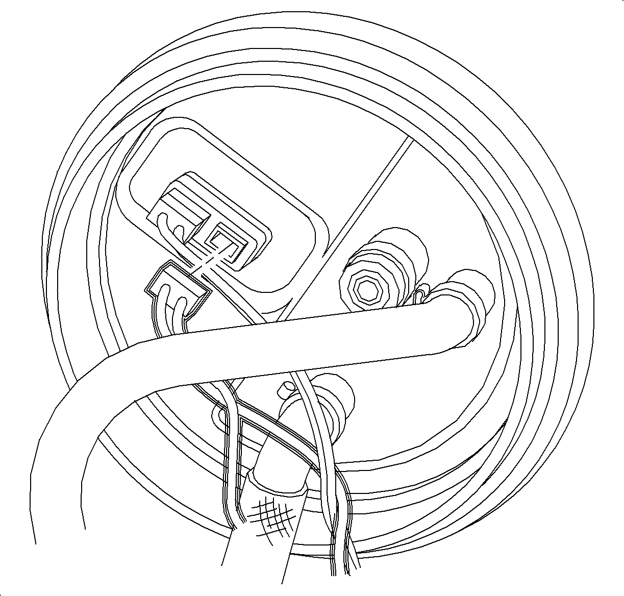
The fuel pump cover connects the fuel pump feed and return lines, provides electrical connection to the fuel pump and fuel level sender, and is the mounting point for fuel tank pressure sensor.
Fuel Level Sender and Sensor
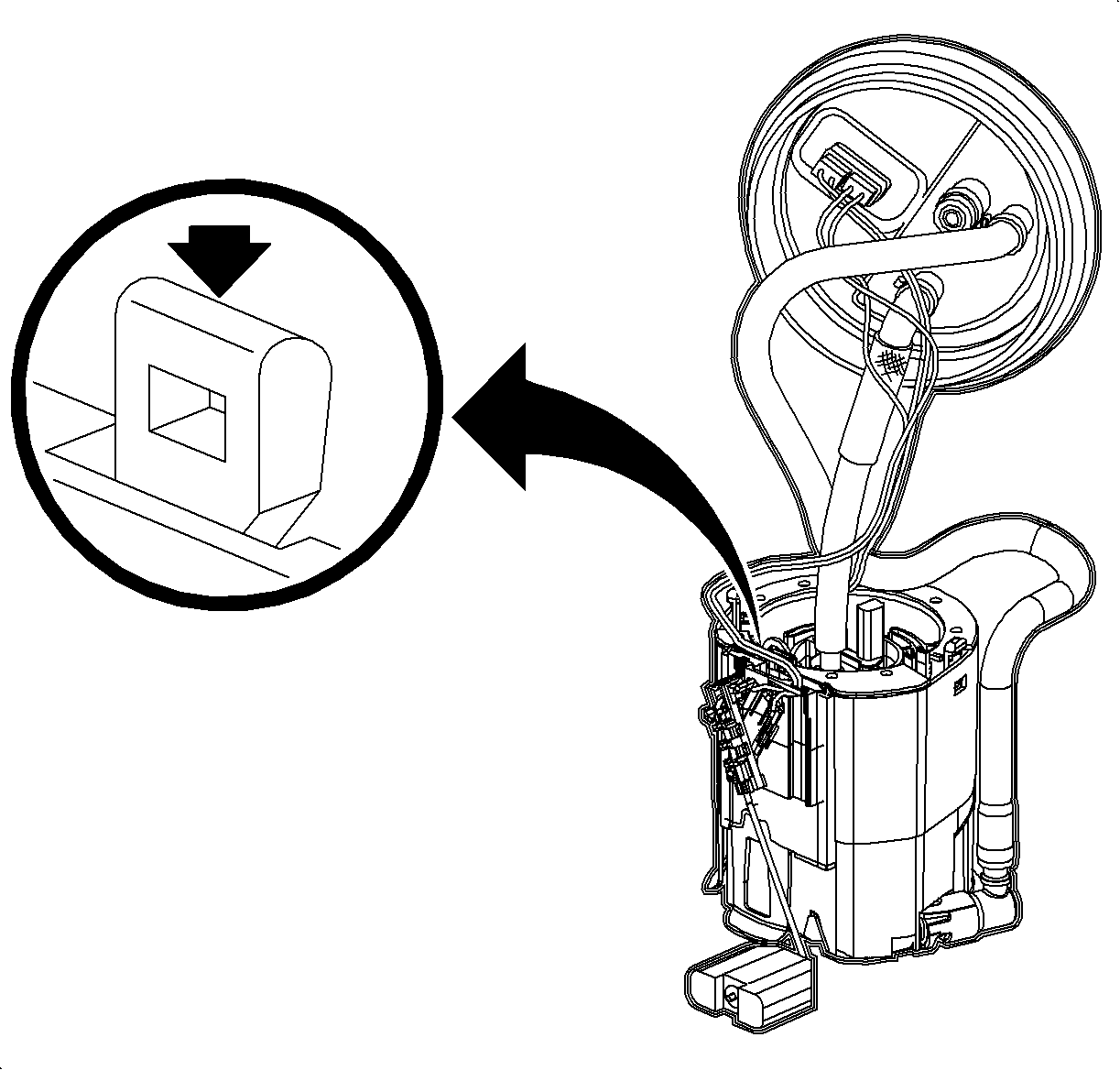
The fuel level sender is a variable resistor that is read by the ECM. The ECM reads resistance and controls the fuel level gage in response to float movements of the sender.
The level sender is mounted on the module housing and is a snap-lock attachment. The sender and float are serviced as a unit.
