For 1990-2009 cars only
Removal Procedure
- Raise the vehicle on the hoist.
- Remove the wheel and tire assembly.
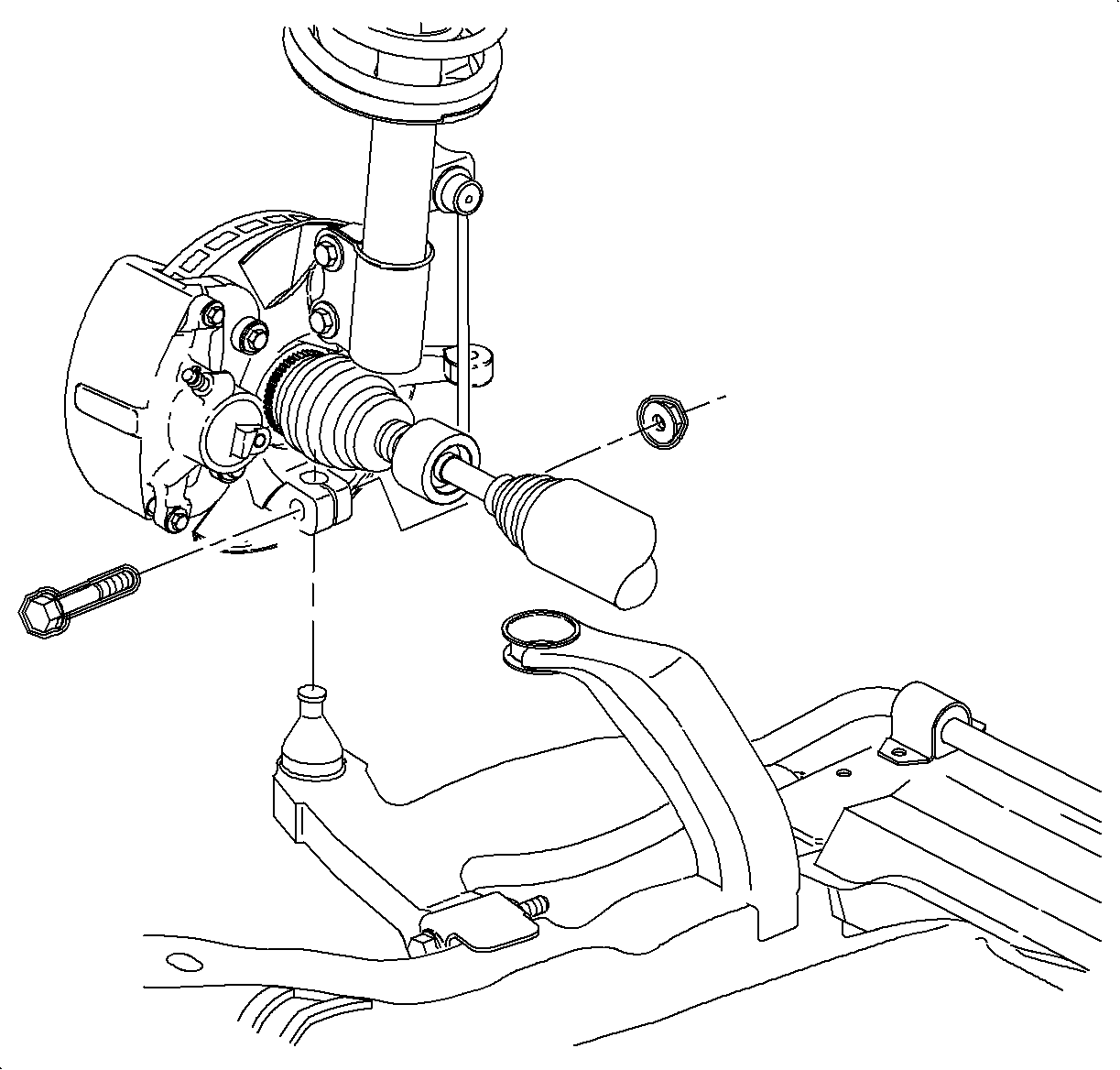
- Remove the ball stud bolt and nut.
- Separate the ball stud from the steering knuckle using a pry bar.
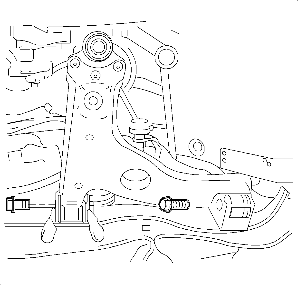
- Remove the lower control arm to frame assembly bolts and discard.
- Remove the lower control arm from the vehicle.
Caution: Refer to Vehicle Lifting Caution in the Preface section.


Notice: Care must be taken to prevent damage to the speed sensor ring on ABS vehicles. Minor surface damage to the speed sensor ring can result in ABS system malfunctions.
Installation Procedure
- Install the control arm onto the frame assembly.
- Install the control arm to the frame using NEW bolts.
- Install the ball stud to the steering knuckle bolt and nut. Hold the bolt while tightening the nut.
- Position the wheel onto the hub
- Install the wheel bolts and tighten in a crisscross pattern.
- Lower the vehicle from the hoist.
- Perform the vehicle alignment. Refer to Wheel Alignment Specifications in Wheel Alignment.

Tighten
Tighten the control arm-to-frame bolts to 90 N·m (66 lb ft)
+ 75-90 degrees.

Important: Use a new bolt and nut. Tighten retention of the old fasteners may not be sufficient.
Tighten
Tighten the lower control arm-to-steering knuckle to 100 N·m (75 lb ft).
Notice: Refer to Wheel Installation Caution in the Preface section.
| 5.1. | Hand tighten all 5 wheel bolts. |
| 5.2. | Use a torque wrench to tighten the wheel bolts using a crisscross pattern. |
Tighten
Tighten the wheel bolts first pass to 63 N·m (46 lb ft).
| 5.3. | Use a torque wrench to final tighten the wheel bolts using a crisscross pattern. |
Tighten
Tighten the wheel bolts final pass to 125 N·m (92 lb ft).
