Stabilizer Shaft Replacement L61
Tools Required
J 43628 Frame Alignment Fixture
Removal Procedure
- Remove the stabilizer bar clamps to the frame fasteners.
- Raise the vehicle on the hoist.
- Remove the wheel and tire assemblies.
- Disconnect the oxygen sensor from the electrical connector.
- Remove the exhaust manifold pipe to the exhaust manifold fasteners.
- Remove the suspension support assemblies and discard the bolts.
- Remove the exhaust manifold pipe to the exhaust pipe fasteners.
- Loosen the remaining frame attachment fastener until the exhaust manifold pipe can be removed from the vehicle.
- Remove the stabilizer bar links from the stabilizer bar.
- Remove the stabilizer bar from the vehicle through the left wheel opening.
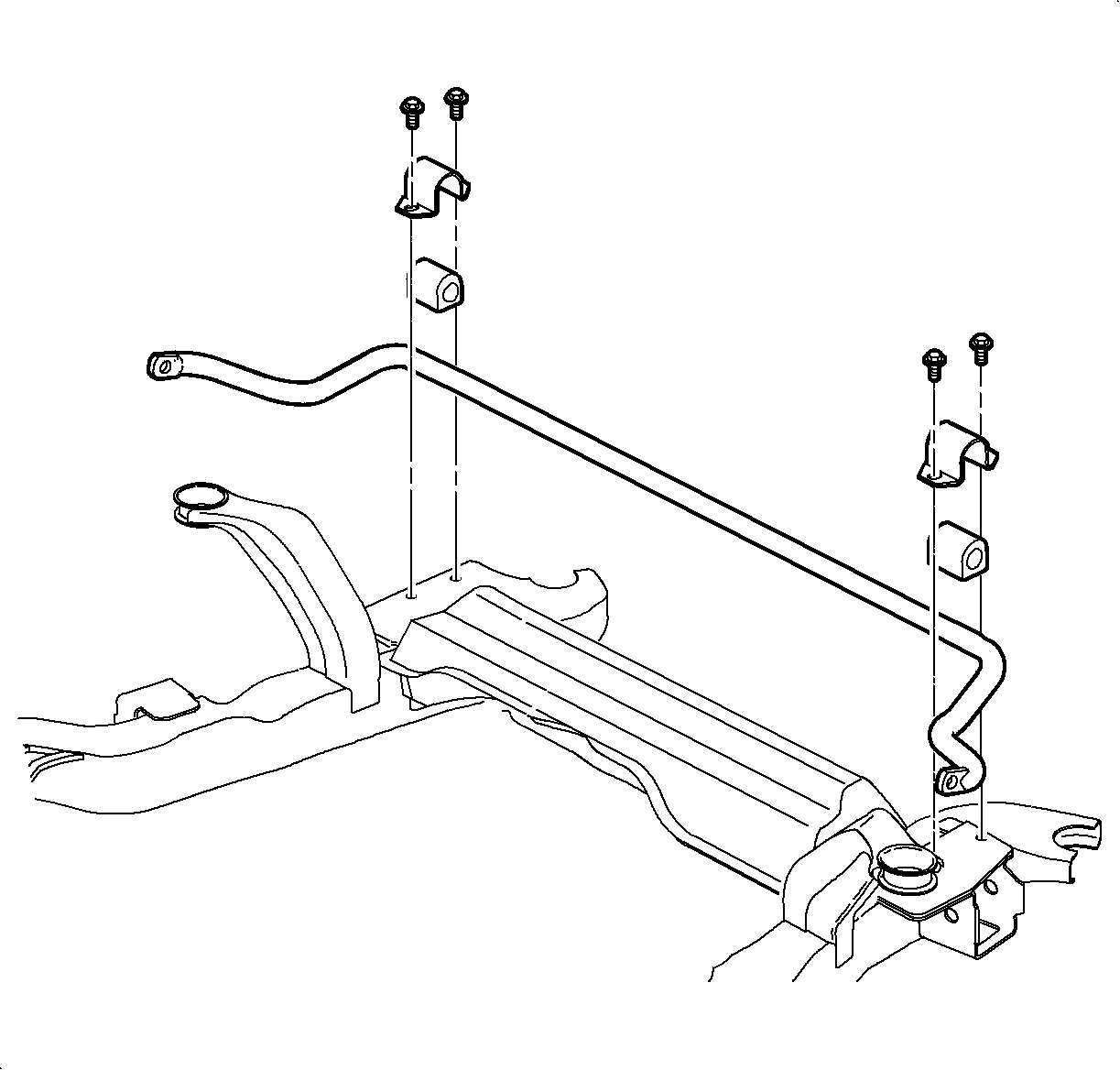
Important: On vehicles equipped with cruise control, it is necessary to remove the left stabilizer bar clamp from under the vehicle.
Caution: Refer to Vehicle Lifting Caution in the Preface section.
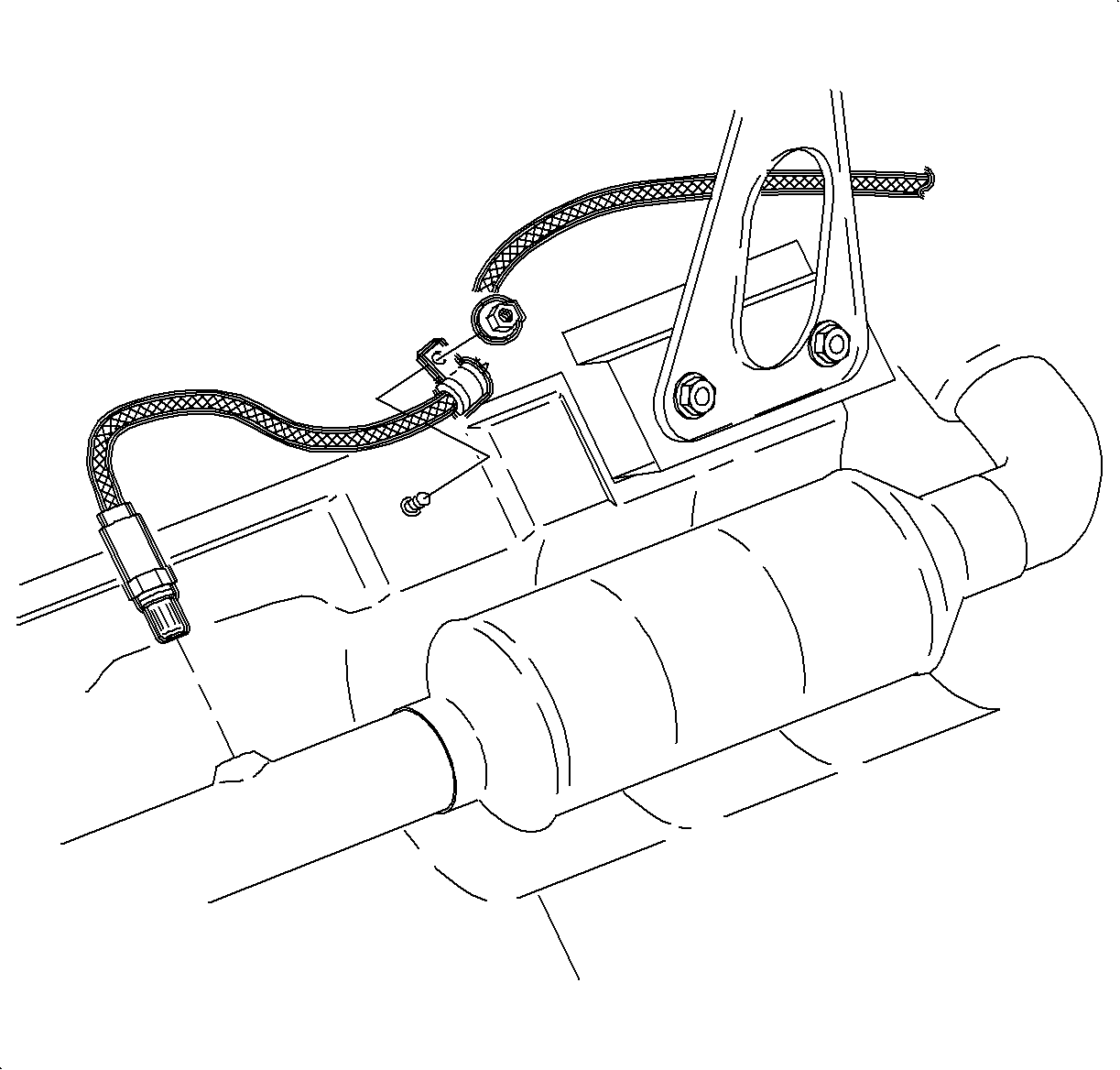
Important: For vehicles equipped with manual transaxles, perform steps 4-8. The exhaust manifold pipe must be removed in vehicles equipped with manual transaxles.
Important: It is not necessary to remove the oxygen sensor from the exhaust manifold pipe.
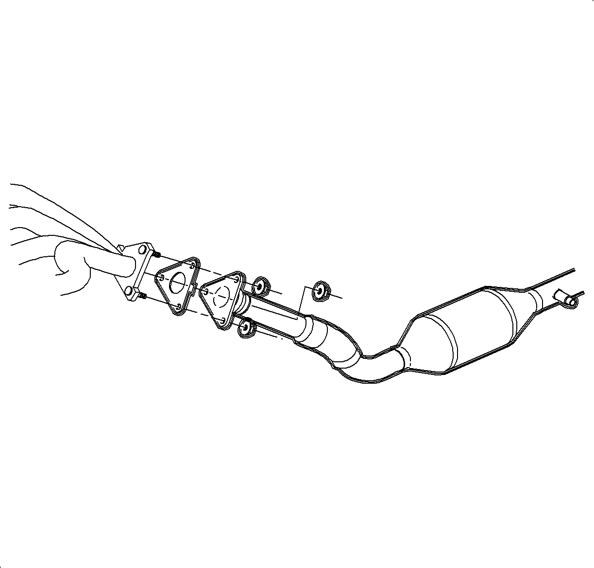
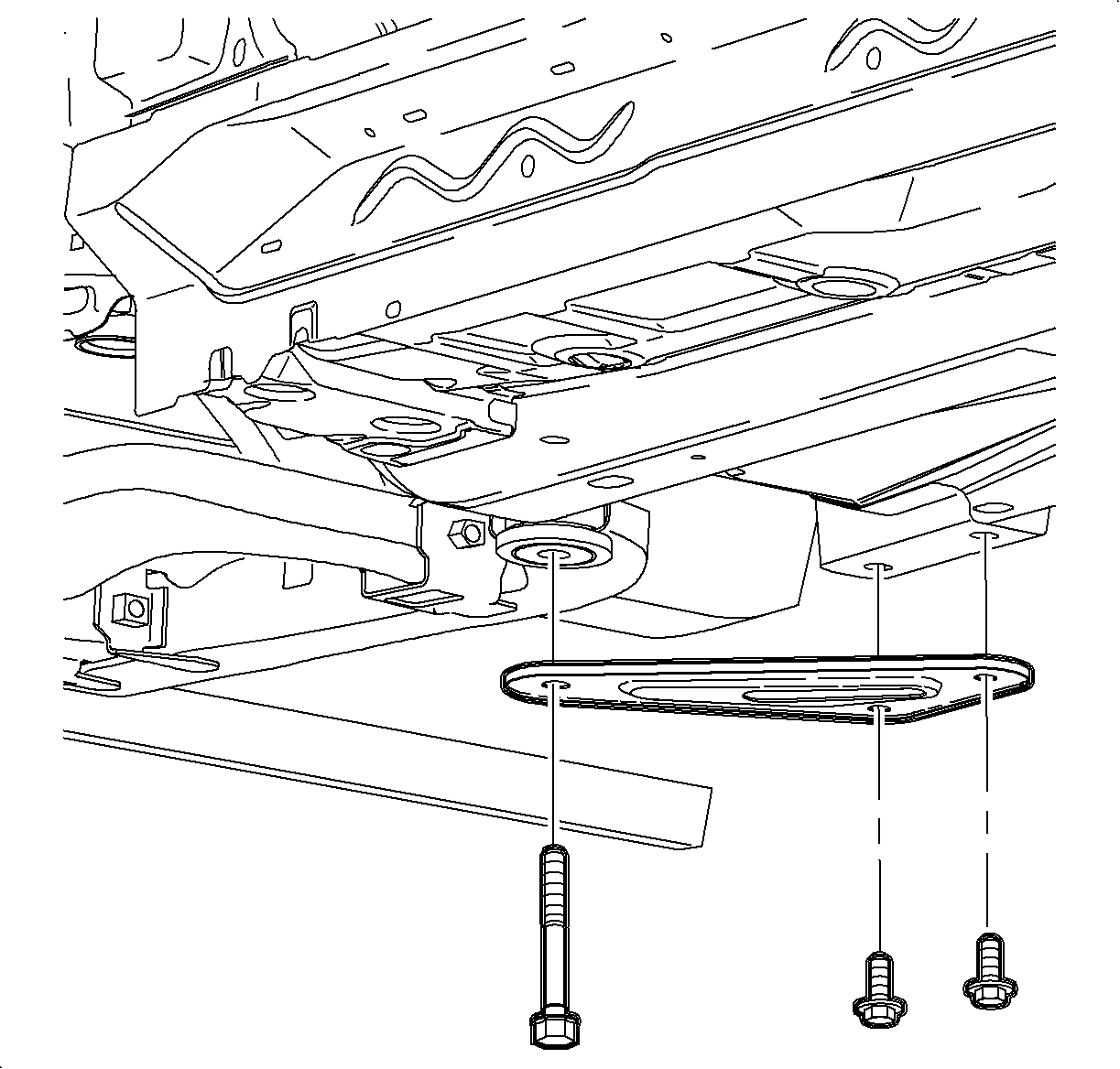
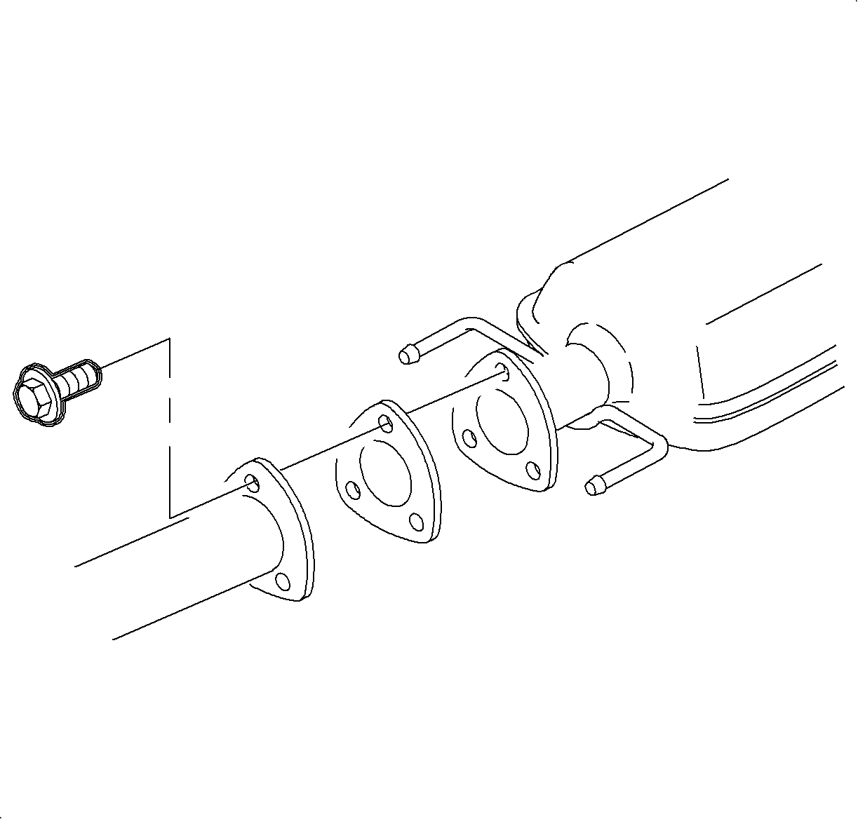
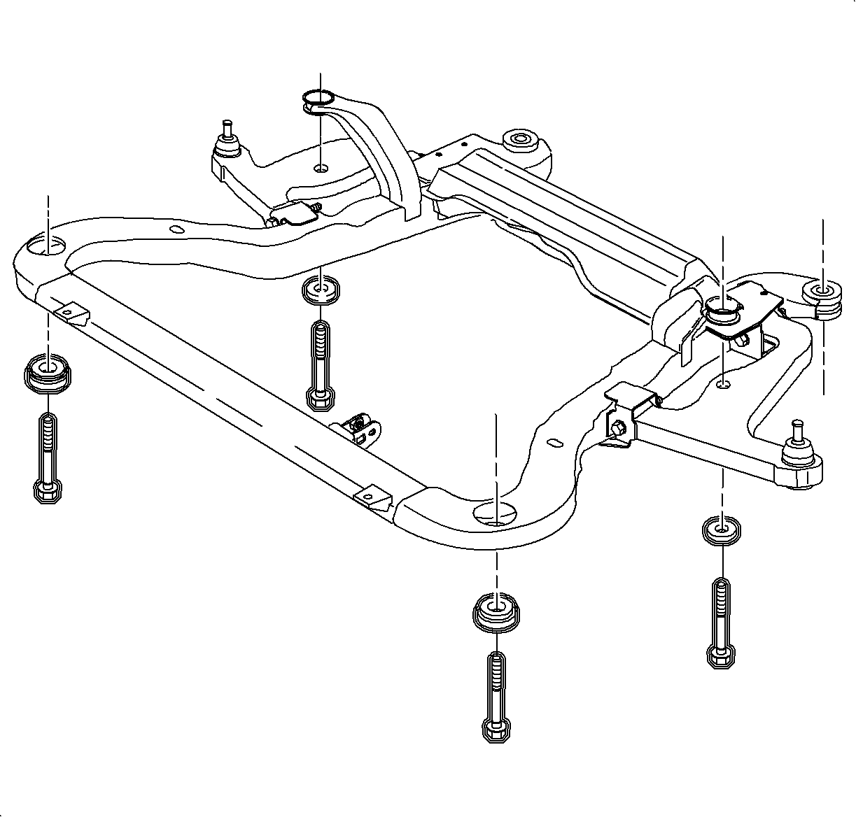
Important: Only loosen the fasteners. Do not remove.
Notice: Refer to Ball Stud Turning Notice in the Preface section.
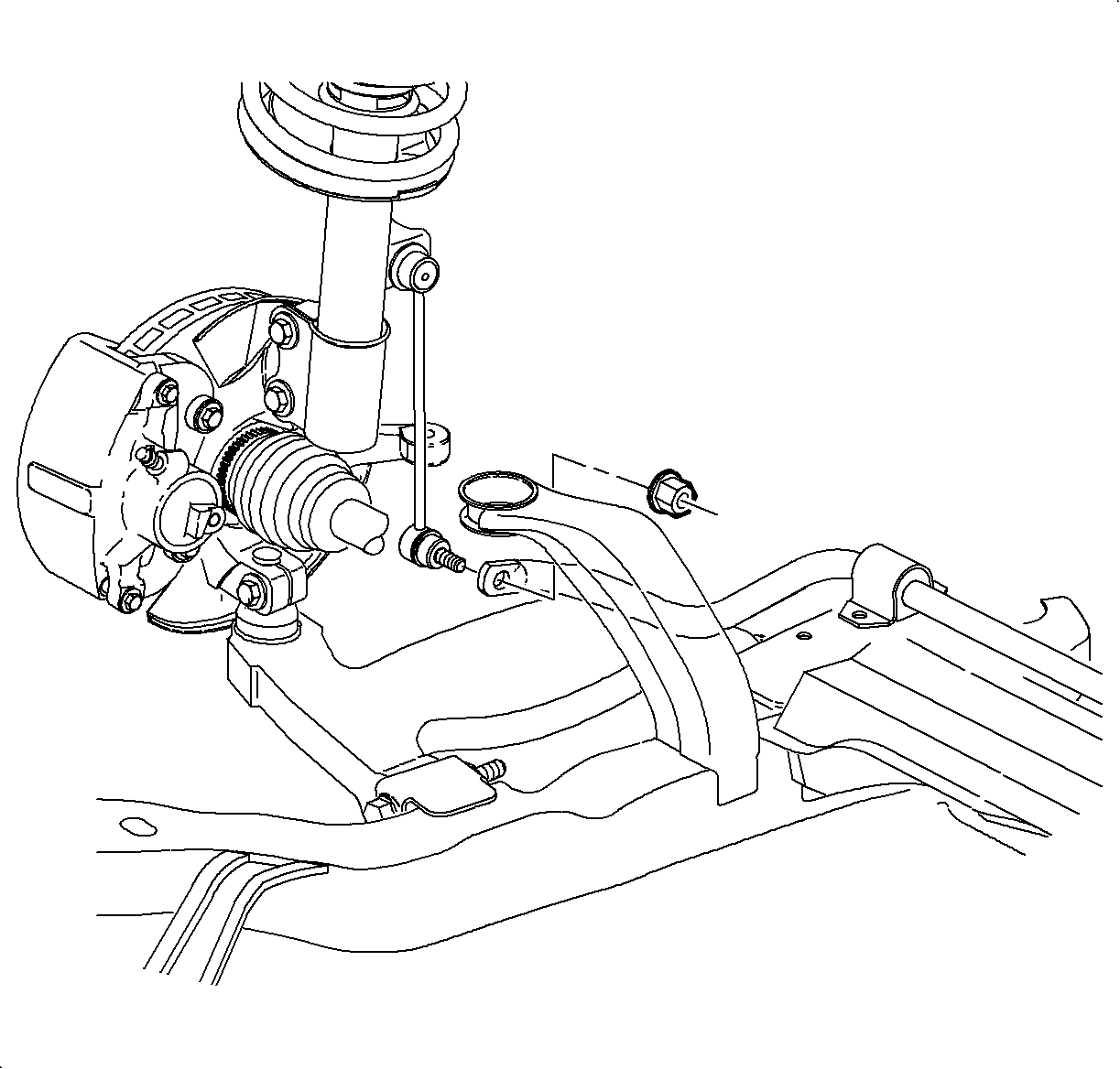
Installation Procedure
- Install the stabilizer bar bushings.
- Install the stabilizer bar through the left wheel opening.
- Install the stabilizer bar clamps and hand tighten.
- Tighten the left side clamp on vehicles equipped with cruise control.
- Install the stabilizer bar links.
- Inspect the boots for damage and replace if damaged.
- Install the exhaust manifold pipe into the vehicle, tighten the exhaust manifold to exhaust manifold pipe fasteners.
- Install the exhaust manifold pipe to the exhaust pipe fasteners.
- Install the J 43628 and raise the frame to the vehicle.
- Remove the remaining frame bolts and nuts and replace with NEW bolts and nuts, and tighten.
- Install the suspension support assemblies using NEW bolts and nuts.
- Connect the oxygen sensor harness to the heat shield.
- Connect the oxygen sensor electrical connector.
- Position the wheel onto the hub.
- Install the wheel bolts and tighten in a crisscross pattern.
- Lower the vehicle from the hoist.
- Tighten the stabilizer bar clamps.
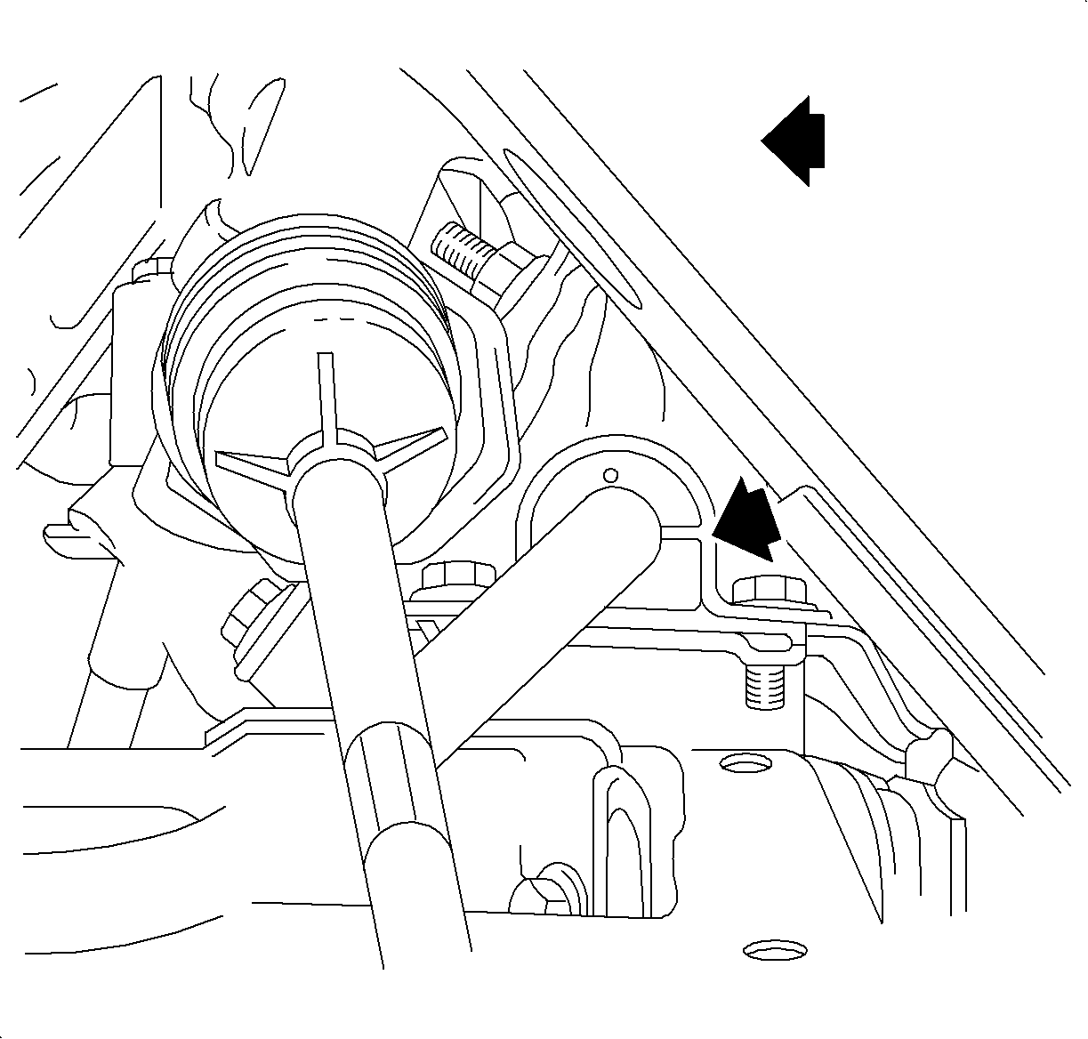
Important: The stabilizer bar bushings must be installed with the slot facing the front of the vehicle.

Important: On vehicles equipped with cruise control, it is necessary to tighten the left stabilizer bar clamp from under the vehicle.
Tighten
Tighten the stabilizer bar clamp-to-frame bolts to 20 N·m (15 lb ft).
Notice: Refer to Ball Stud Turning Notice in the Preface section.

Tighten
Tighten the stabilizer bar link-to-strut to 65 N·m (48 lb ft).

Important: For vehicles equipped with manual transaxles, perform steps 7-13. The exhaust manifold pipe must be installed in vehicles equipped with manual transaxles.
Tighten
Tighten the exhaust manifold pipe-to-exhaust manifold nuts to 30 N·m
(22 lb ft).

Tighten
Tighten the exhaust manifold pipe-to-resonator bolts to 20 N·m
(15 lb ft).
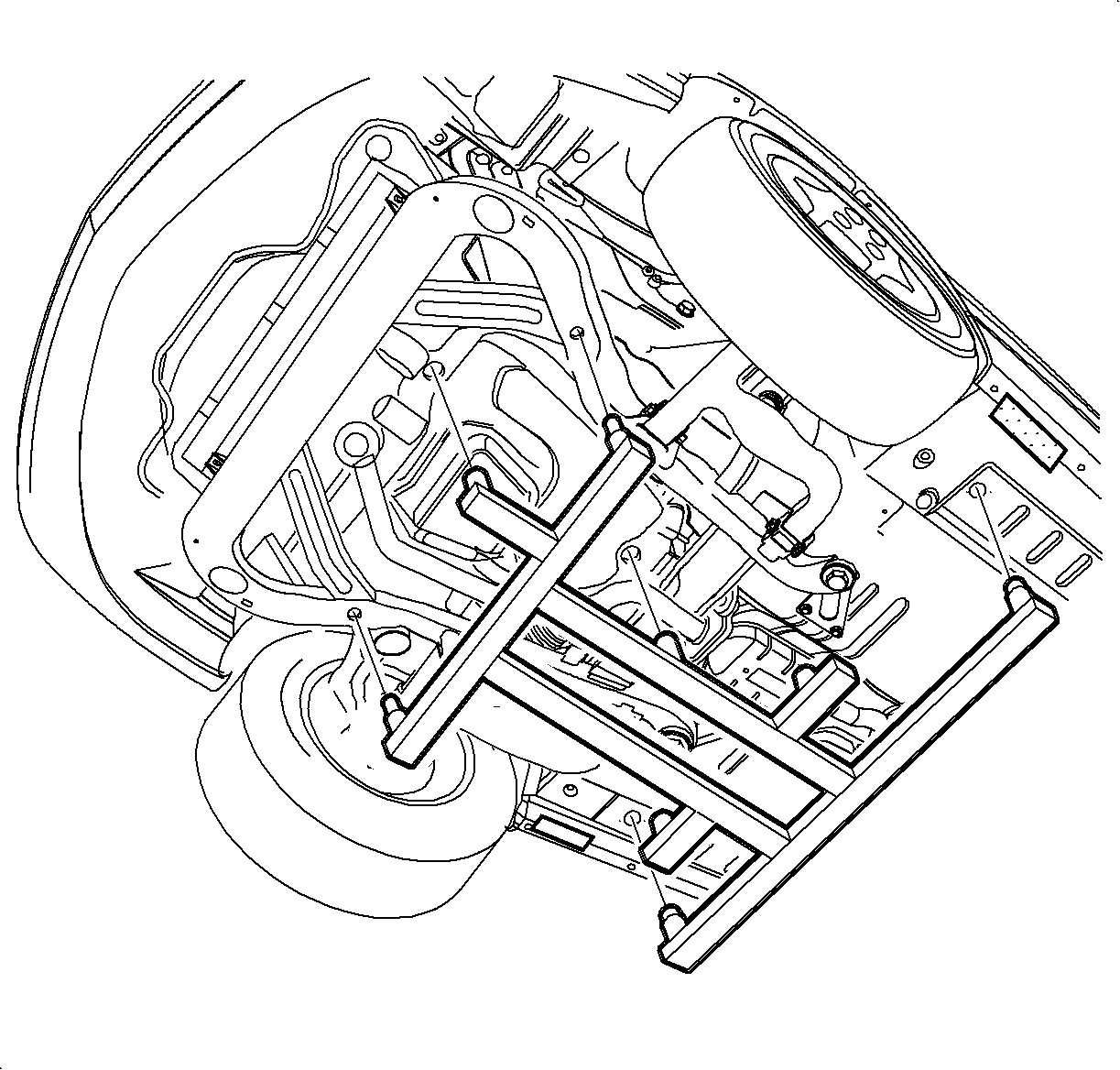

Important: New bolts and nuts must be used; tighten retention of old bolts and nuts may not be sufficient.
Tighten
Tighten the frame assembly-to-body bolts to 90 N·m (66 lb ft)
+ 45-60 degrees.

Important: New bolts and nuts must be used; tighten retention of old bolts and nuts may not be sufficient.
Tighten
Tighten the suspension support-to-body bolts to 90 N·m (66 lb ft)
+ 45-60 degrees.

Tighten
Tighten the O2 sensor lip-to-underbody attachment nut to 4 N·m
(35 lb in).
Notice: Refer to Wheel Installation Caution in the Preface section.
| 15.1. | Hand tighten all 5 wheel bolts. |
| 15.2. | Use a torque wrench to tighten the wheel bolts using a crisscross pattern. |
Tighten
Tighten the wheel bolts first pass to 63 N·m (46 lb ft).
| 15.3. | Use a torque wrench to final tighten wheel bolts using a crisscross pattern. |
Tighten
Tighten the wheel bolts final pass to 125 N·m (92 lb ft).
Tighten
Tighten the stabilizer bar clamp-to-frame bolts to 20 N·m (15 lb ft).
Stabilizer Shaft Replacement L81
Removal Procedure
- Remove the stabilizer bar clamp bolts from the frame.
- Remove the exhaust manifold pipe heat shield.
- Raise the vehicle on the hoist.
- Remove the wheel and tire assemblies.
- Disconnect the oxygen sensor electrical connector and remove the oxygen sensor from the exhaust manifold pipe.
- Remove the exhaust manifold pipe fasteners and remove the pipe from the vehicle.
- Remove the stabilizer link to the stabilizer bar fasteners.
- Remove the stabilizer bar through the left wheel opening.

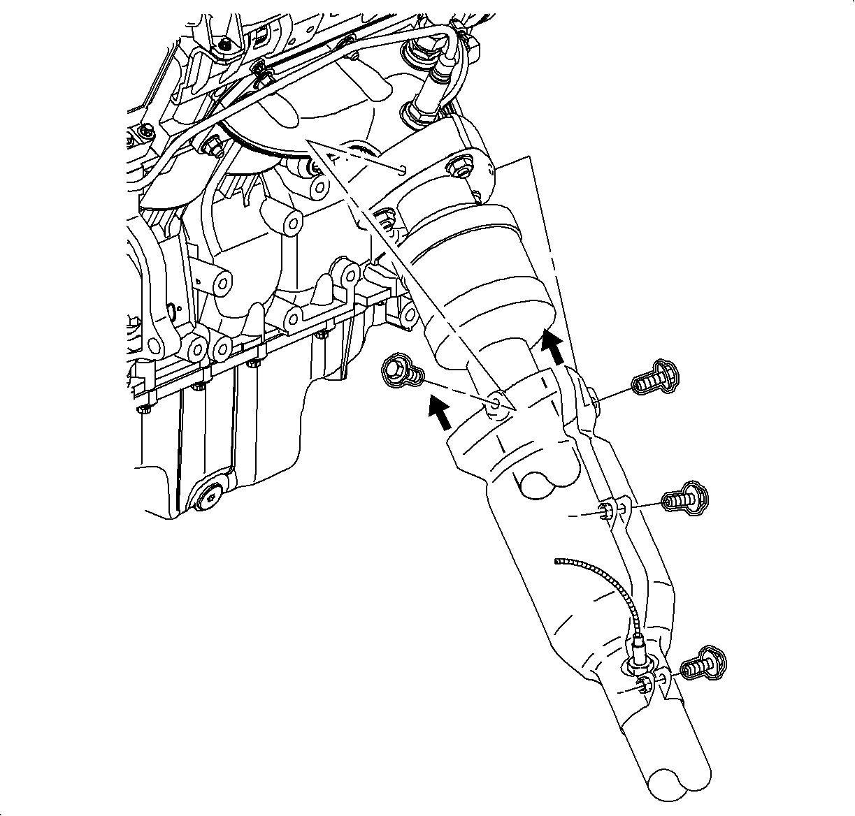
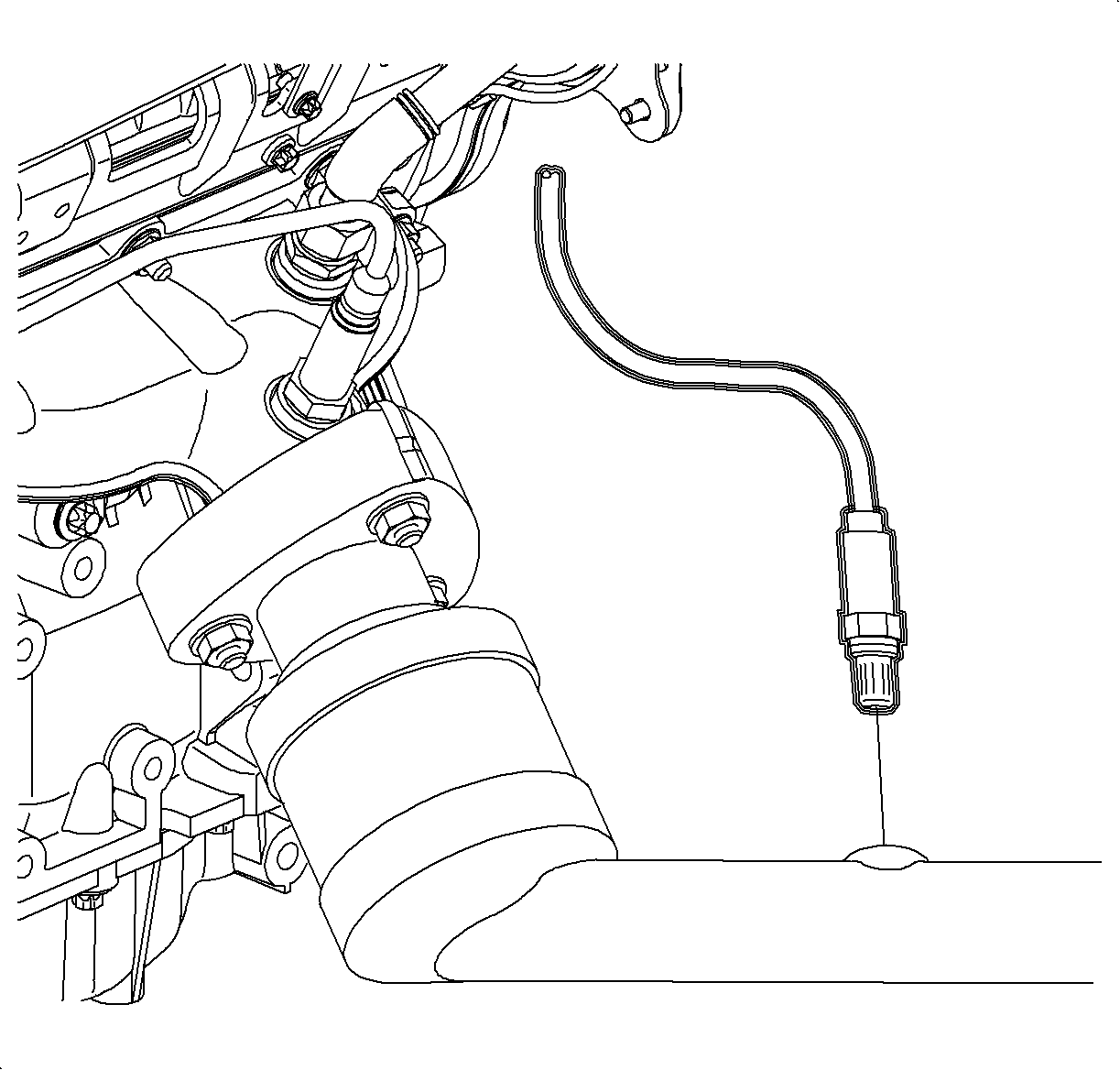
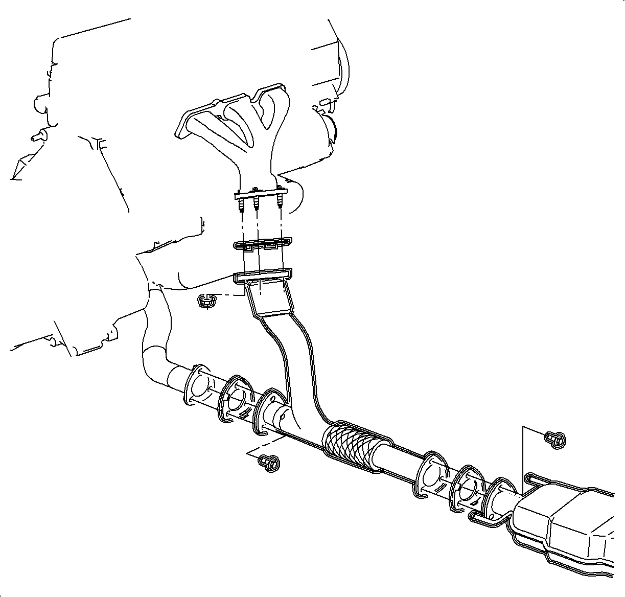
Notice: Refer to Ball Stud Turning Notice in the Preface section.

Installation Procedure
- Install the stabilizer bar bushings.
- Install the stabilizer bar through the left wheel opening.
- Install the clamps and hand tighten.
- Install the stabilizer bar links.
- Inspect the boots for damage and replace if damaged.
- Install the exhaust manifold pipe.
- Tighten the exhaust manifold pipe to exhaust manifold fasteners.
- Tighten the exhaust manifold pipe to exhaust pipe fasteners.
- Position the wheel onto the hub.
- Install the wheel bolts and tighten in a crisscross pattern.
- Lower the vehicle from the hoist.
- Install the exhaust manifold pipe heat shield.
- Tighten the stabilizer bar clamps.

Important: The stabilizer bar bushings must be installed with the slot facing the front of the vehicle.


Notice: Hold the ball stud from turning when removing/installing the nut. The boot can become torn and damaged if the ball stud turns.
Tighten
Tighten the stabilizer bar-to-stabilizer bar link to 65 N·m (48 lb ft).

Tighten
Tighten the exhaust manifold pipe-to-exhaust manifold nuts to 30 N·m
(22 lb ft).
Tighten
Tighten the exhaust manifold pipe-to-exhaust pipe bolts to 20 N·m
(15 lb ft).
Notice: Refer to Wheel Installation Caution in the Preface section.
| 10.1. | Hand tighten all 5 wheel bolts. |
| 10.2. | Use a torque wrench to tighten the wheel bolts using a crisscross pattern. |
Tighten
Tighten the wheel bolts first pass to 63 N·m (46 lb ft).
| 10.3. | Use a torque wrench to final tighten the wheel bolts using a crisscross pattern. |
Tighten
Tighten the wheel bolts final pass to 125 N·m (92 lb ft).

Tighten
Tighten the exhaust manifold pipe heat shield bolts (L81) to 8 N·m
(71 lb in).

Tighten
Tighten the stabilizer bar clamp-to-frame bolts to 20 N·m (15 lb ft).
