Tools Required
SA91100C Tie Rod Separator
Removal Procedure
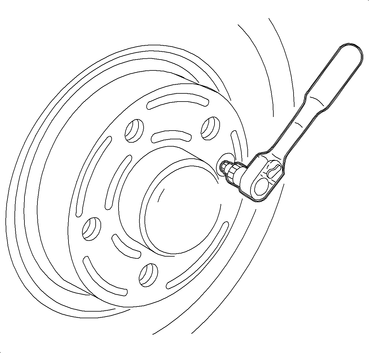
- Remove the wheel cover on the base wheels or the center cap on the up-level aluminum wheel.
- With the vehicle on the ground, remove the cotter, depress the brake pedal and loosen the axle-to-hub nut.
- Raise the vehicle on the hoist.
- Remove the wheel and tire assembly.
- Remove the caliper mount bracket-to-steering knuckle bolts; remove the caliper assembly and suspend it from the strut spring with mechanics wire.
- Remove the rotor screw.
- Remove the rotor.
- Remove the dust shield screw and dust shield.
- If equipped, remove the ABS sensor and bracket assembly.
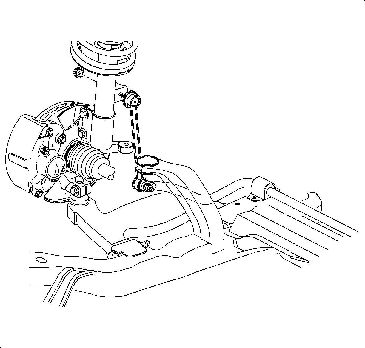
- Loosen the steering knuckle to strut fasteners.
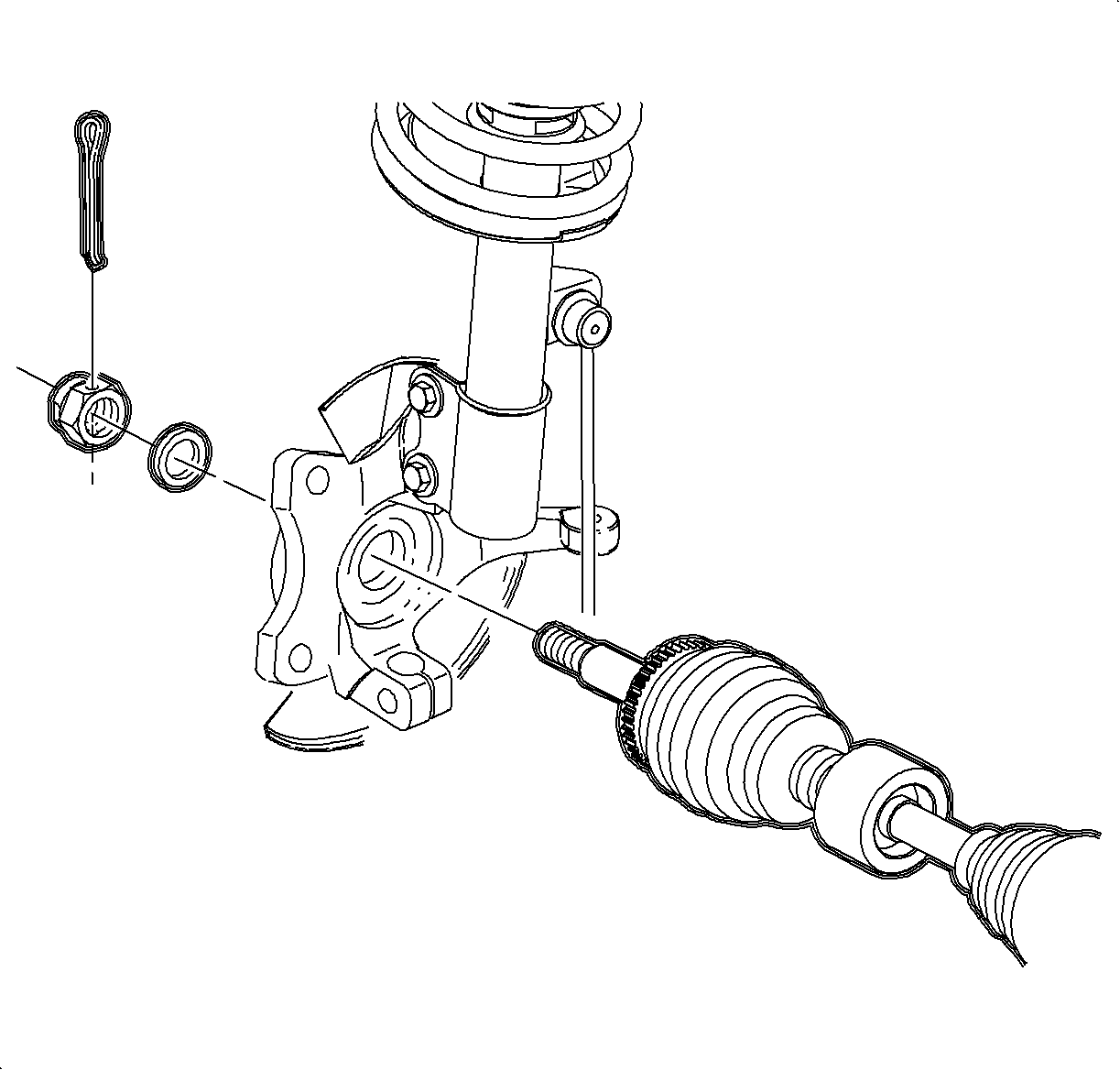
- Remove the axle-to-hub nut and discard.
- Remove and discard the tie rod end nut.
- Using SA91100C Tie Rod Separator, or equivalent, separate the tie rod from the steering knuckle.
- Remove the lower ball stud bolt and nut.
- Separate the lower control arm from the knuckle.
- Suspend or support the drive axle from the strut spring with mechanics wire.
- Pull the knuckle assembly away from the vehicle to release the axle. If difficulty is encountered in separating the axle from the hub, tap on the end of the drive axle shaft using a block of wood and a hammer. Do not hammer directly on the end of the axle.
- Remove the steering knuckle to the strut fastener and remove the knuckle/wheel hub assembly from the vehicle.
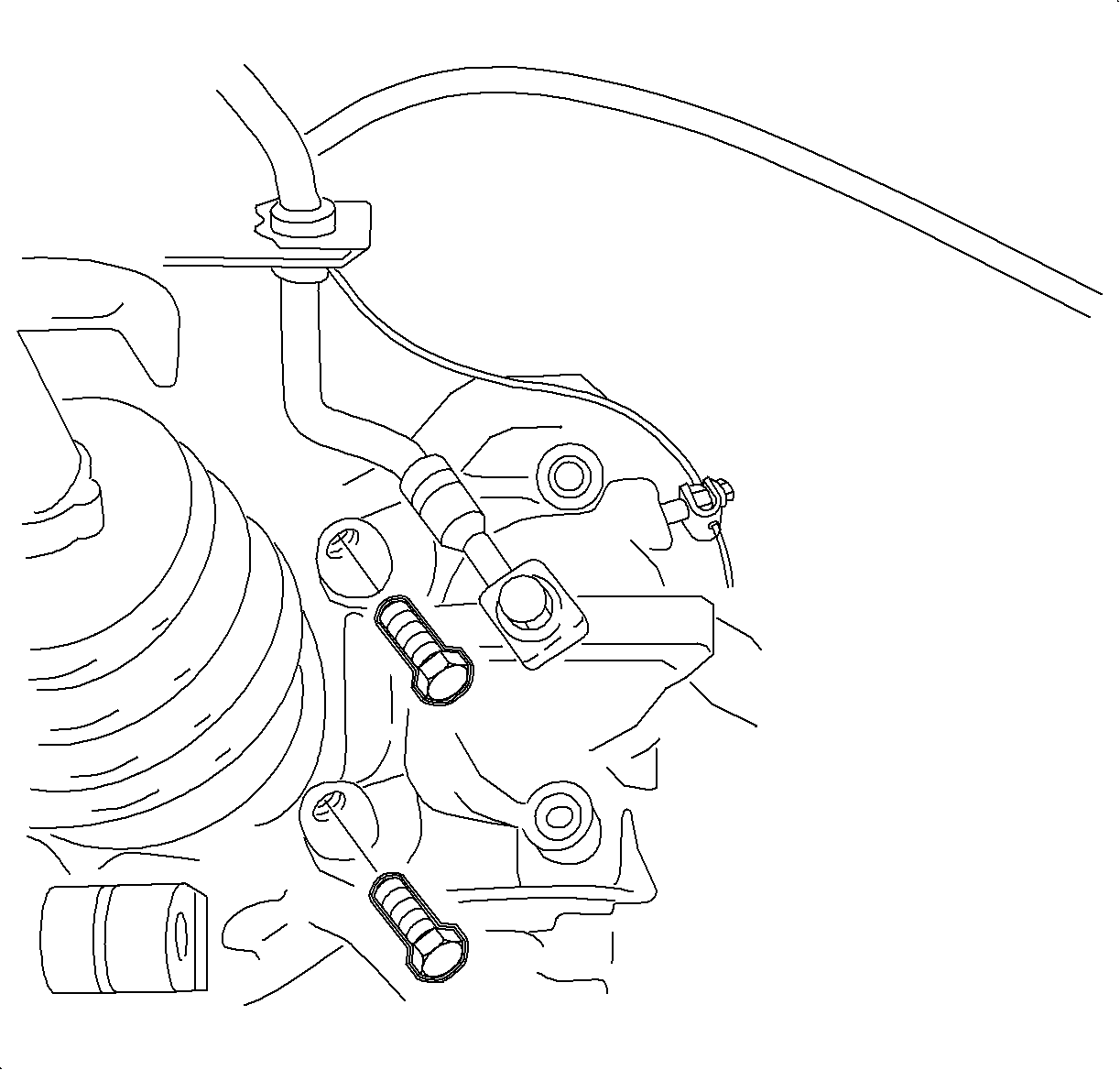
Caution: Refer to Vehicle Lifting Caution in the Preface section.
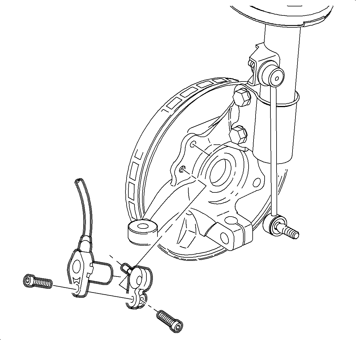
Notice: Wheel speed sensor bracket uses a locating pin on the steering knuckle. Be careful not to break the pin when removing the bracket.
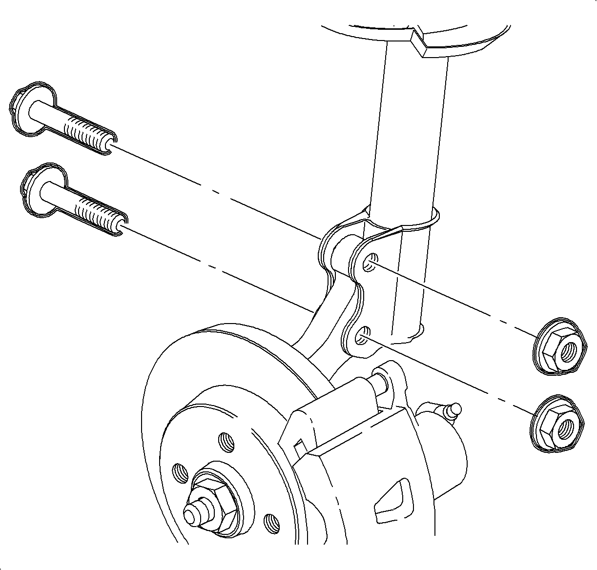
Important: Do not remove the fasteners at this time.
Notice: Refer to Ball Stud Turning Notice in the Preface section.
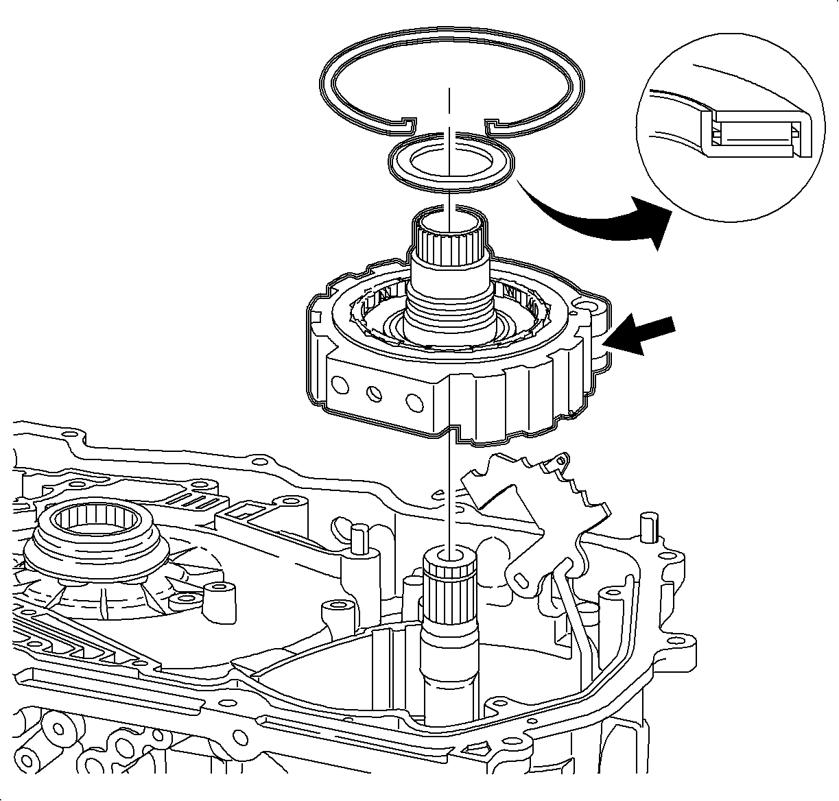
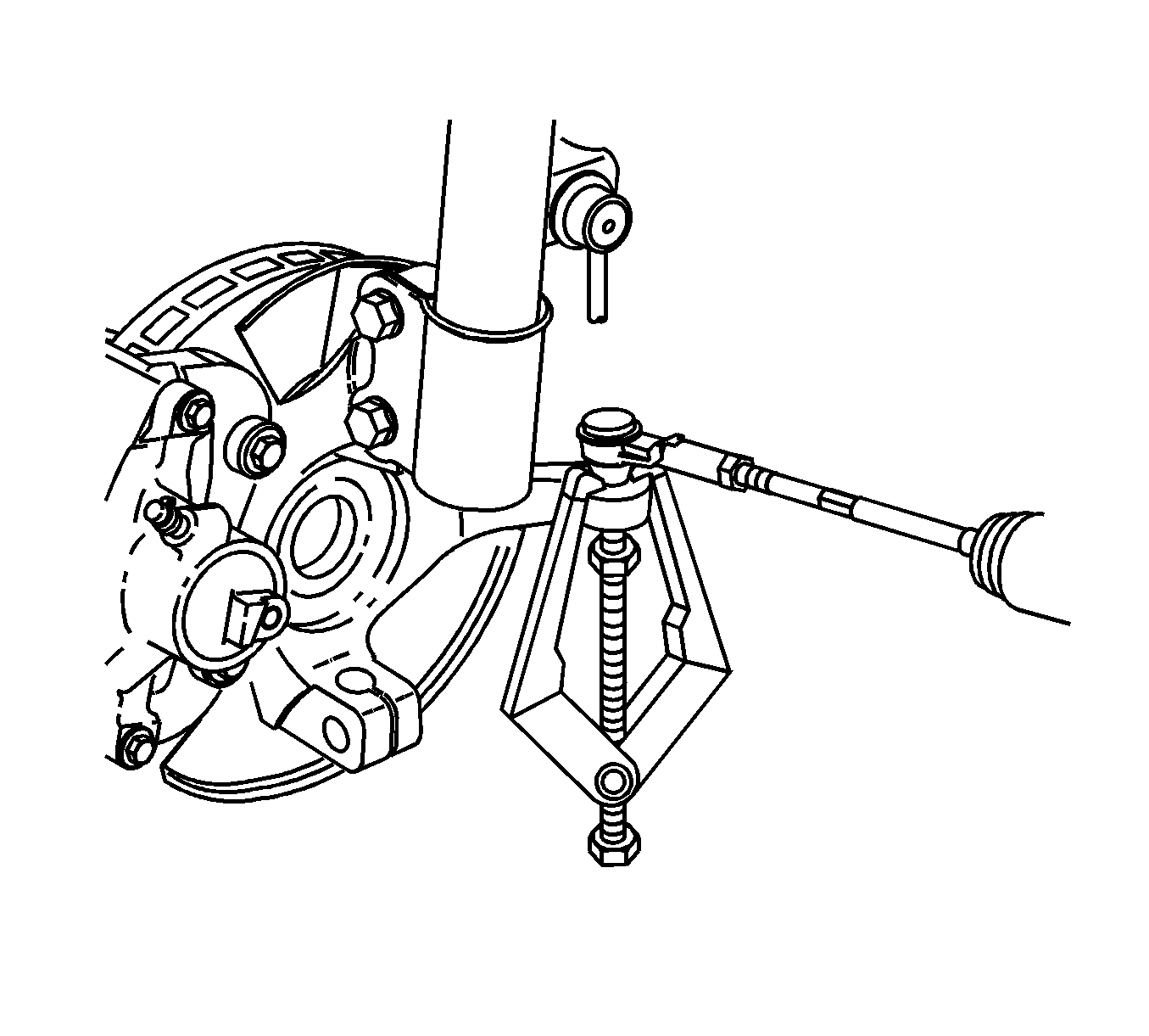
Notice: Do not attempt to separate the joint using a wedge-type tool because seal may be damaged.
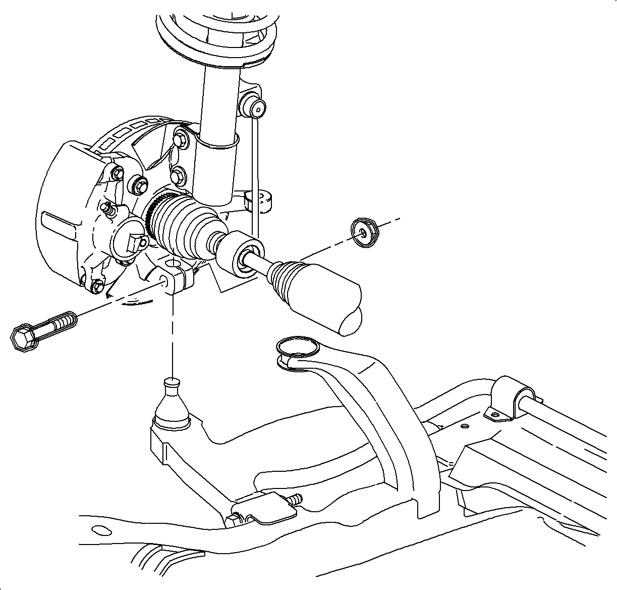
Notice: Place a cloth over the ball stud boot, protecting it from damage caused by contact with steering knuckle.
Notice: Be careful not to allow steering knuckle to contact the ball stud seal. Contact may cause the seal to rip, requiring control arm replacement.
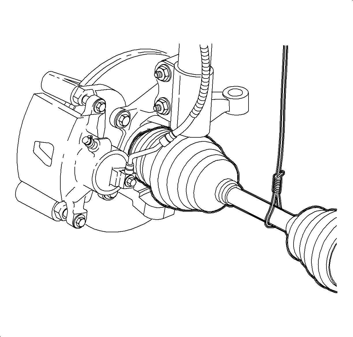
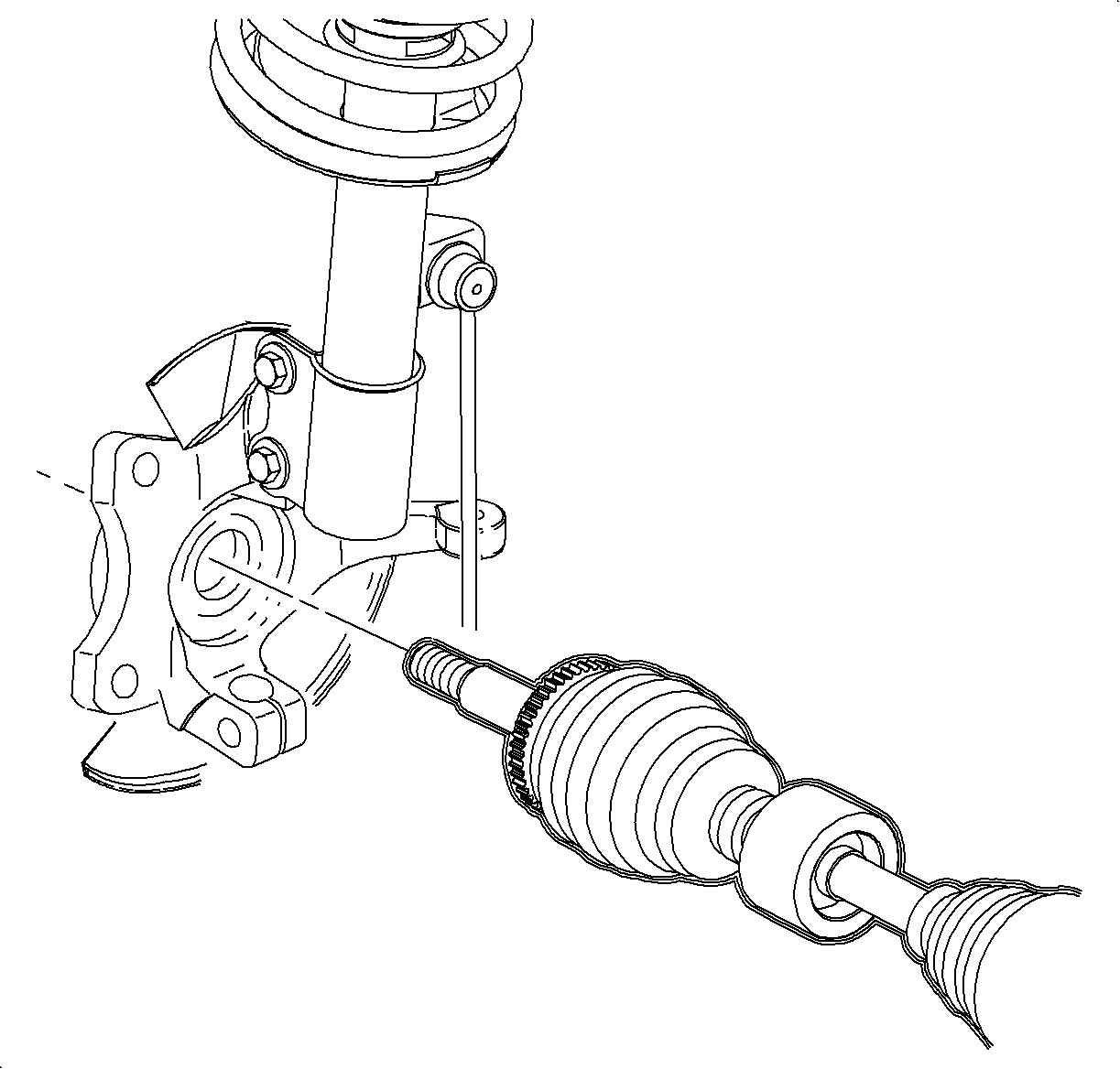
Important: Never pull on the shaft assembly.
Installation Procedure
- Position the steering knuckle onto the axle shaft and install the axle to the hub washer and a NEW nut.
- Attach the steering knuckle to the strut assembly using NEW bolts and nuts.
- Install the ball stud through the knuckle attachment point and install the bolt and nut.
- Tighten the steering knuckle to the strut assembly fasteners in the following sequence using a SA9140E or equivalent.
- Tighten the lower control arm-to-steering knuckle. Hold the bolt stationary and tighten the nut.
- Using the J 44015 or equivalent, install the tie rod end into the steering knuckle.
- Remove the linkage installer and install a new nut.
- Inspect the boot for damage and replace the part if damaged.
- If equipped with ABS, install the sensor mounting bracket and sensor.
- Install the dust shield and tighten the screws.
- Install the rotor and tighten the rotor screw.
- Install the caliper mount bracket onto the knuckle.
- Position the wheel onto the hub.
- Install the wheel bolts and tighten in a crisscross pattern.
- Lower the vehicle from the hoist.
- Depress the brake pedal and tighten the axle to the hub nut in the following sequence:
- Install the cotter pin.
- Perform the vehicle wheel alignment. Refer to Wheel Alignment Specifications in Wheel Alignment.
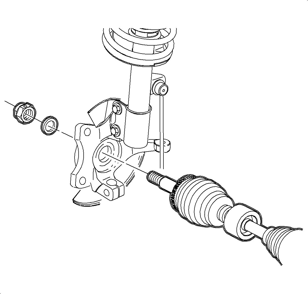

Important: Do not tighten the fastener at this time.

Important: Do not tighten the fastener at this time.

Tighten
| • | Tighten the front strut-to-knuckle first pass to 50 N·m (37 lb ft). |
| • | Tighten the front strut-to-knuckle final pass to 100 N·m (73 lb ft) + 30-45 degrees. |

Tighten
Tighten the lower control arm-to-steering knuckle to 100 N·m (75 lb ft).
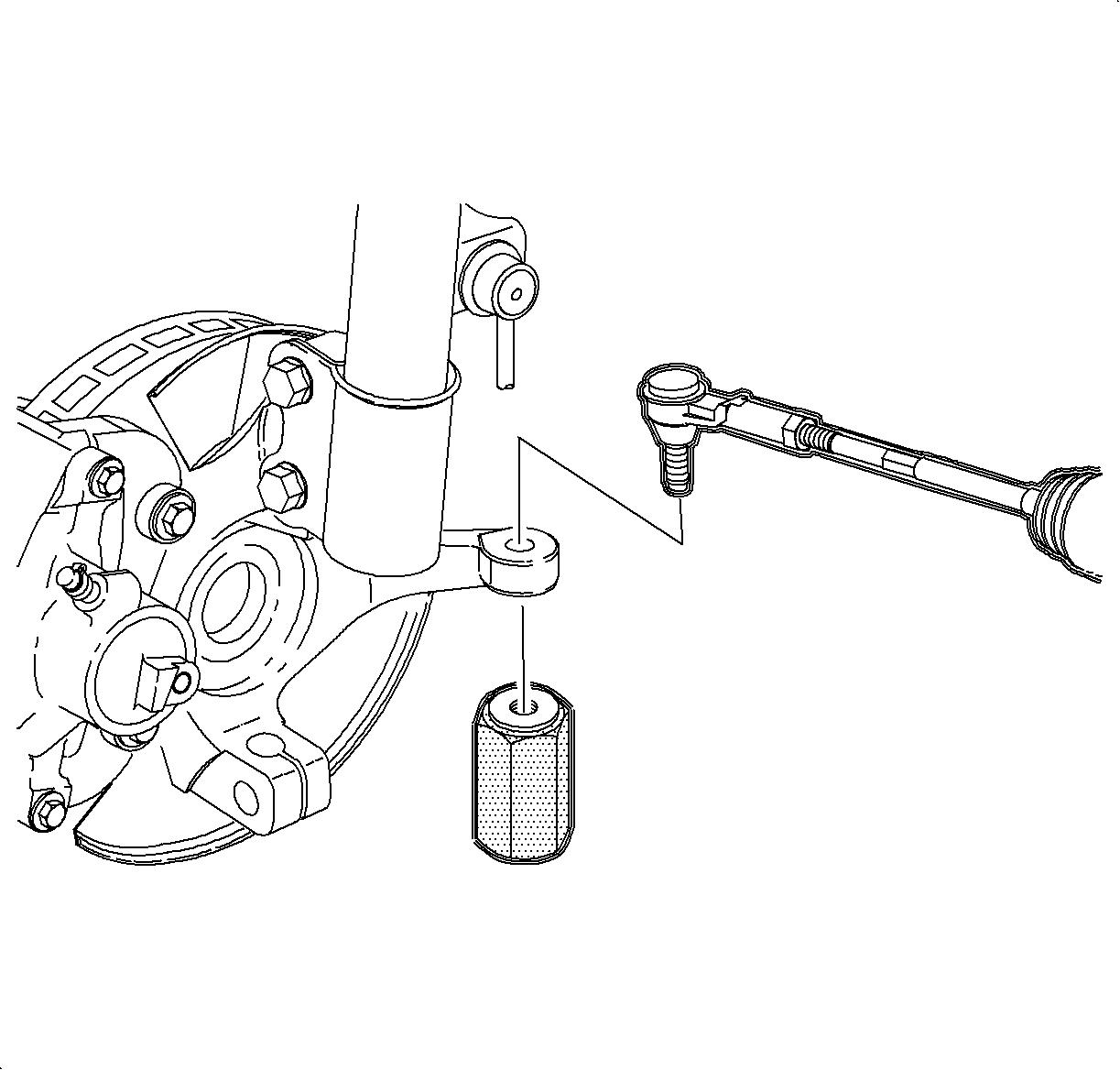
Important: The tie rod ends must be thoroughly cleaned before tightening the nut.
Tighten
Tighten the tie rod end linkage installer to 45 N·m (33 lb ft).
Notice: Refer to Ball Stud Turning Notice in the Preface section.
Important: Use a new nut. Tighten retention of an old nut may not be sufficient.
Tighten
Tighten the tie rod end-to-knuckle nut to 60 N·m (45 lb ft).

Tighten
Tighten the ABS sensor bracket-to-knuckle to 8 N·m (71 lb in).
Tighten
Tighten the ABS sensor-to-bracket to 4 N·m (35 lb in).

Tighten
Tighten the front rotor-to-hub to 3.5 N·m (27 lb in).

Important: Apply Loctite 242® Threadlocker, or equivalent, on the threads of the caliper bracket bolts.
Tighten
Tighten the caliper mount bracket-to-knuckle to 95 N·m (70 lb ft).
Notice: Refer to Wheel Installation Caution in the Preface section.
| 14.1. | Hand tighten all 5 wheel bolts. |
| 14.2. | Use a torque wrench to tighten the wheel bolts using a crisscross pattern. |
Tighten
Tighten the wheel bolts first pass to 63 N·m (46 lb ft).
| 14.3. | Use a torque wrench to final tighten the wheel bolts using a crisscross pattern. |
Tighten
Tighten the wheel bolts final pass to 125 N·m (92 lb ft).

Tighten
| • | Tighten the nut to 115 N·m (85 lb ft) to seat the bearing back nut off . |
| • | Using a torque angle gage, retighten the nut to 20 N·m (15 lb ft) + 90 degrees. |
If required, continue turning the nut until a cotter hole aligns with the castle nut slot.
