Removal Procedure
- Disable the SIR system. Refer to Disabling the SIR System in SIR.
- Remove SIR coil assembly. Refer to Inflatable Restraint Steering Wheel Module Coil Replacement in SIR.
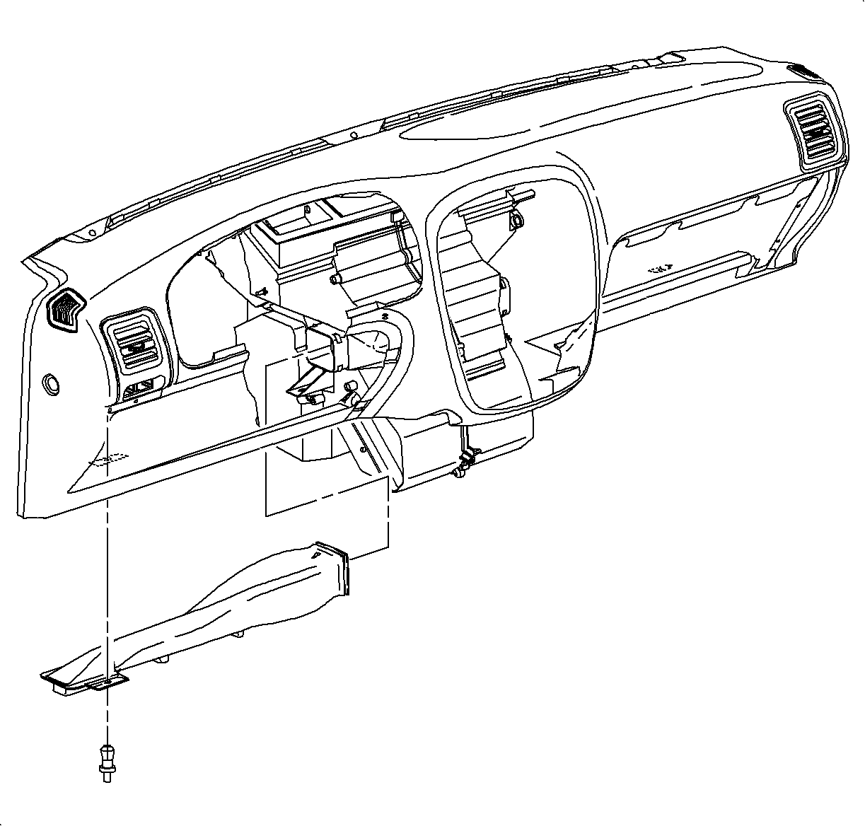
- Remove HVAC duct.
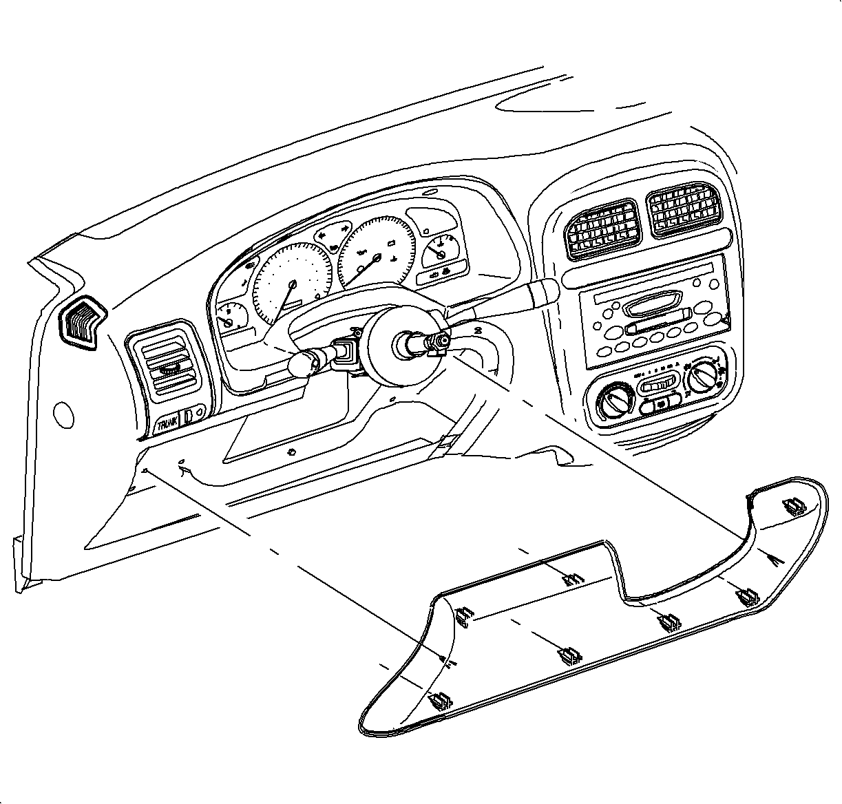
- Remove knee bolster.
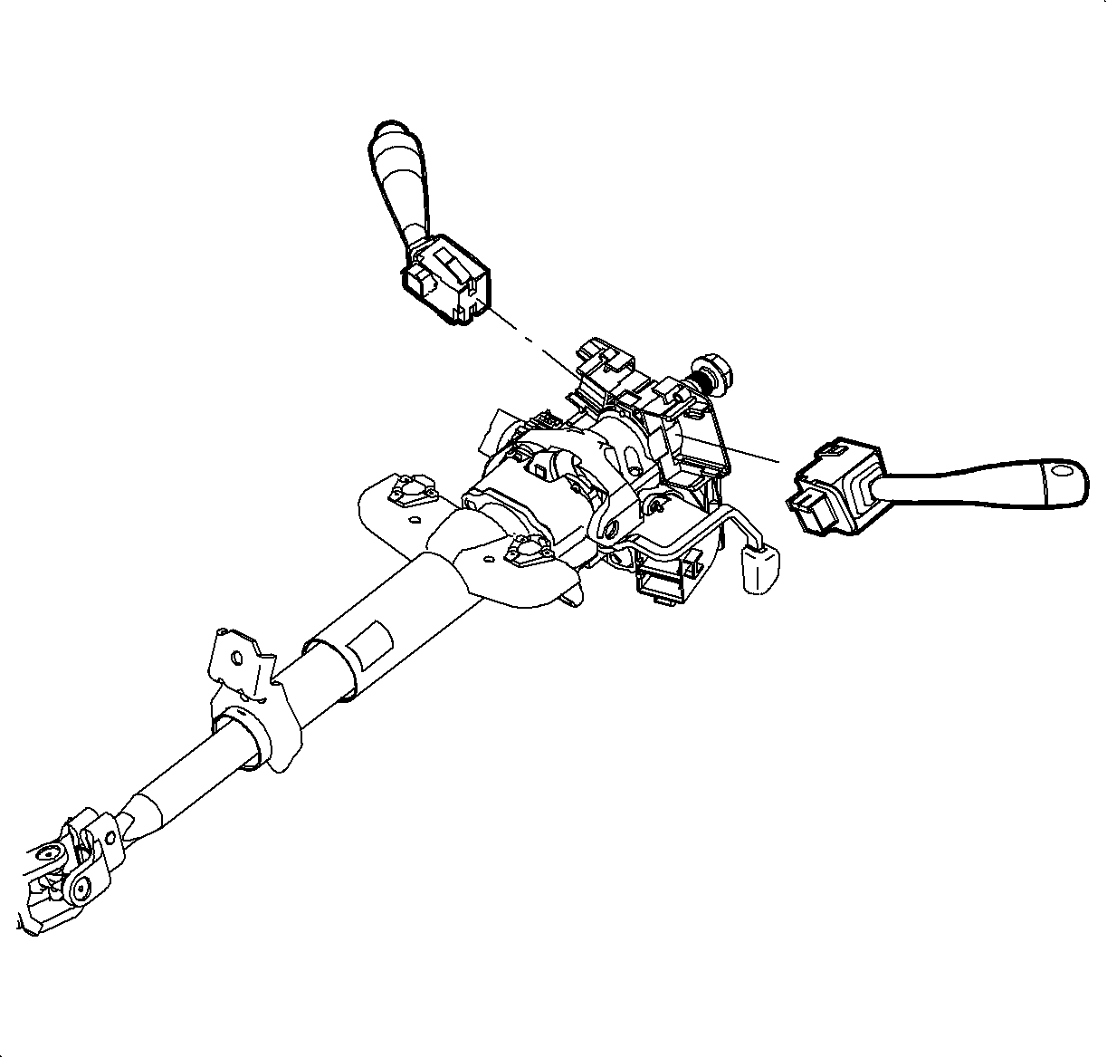
- Disconnect connectors at wiper/washer switch and headlamp/turn switch.
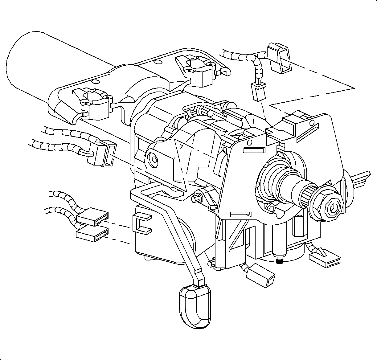
- Disconnect ignition switch electrical connectors at left of steering column.
- Disconnect interlock solenoid electrical connector at right of steering column.
- Disconnect ignition switch connector at right of column.
- Remove wiper/washer and headlamp/turn signal switch.
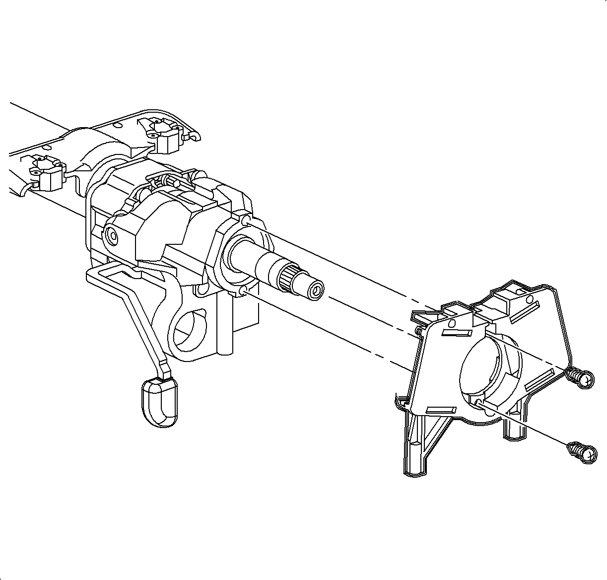
- Remove signal switch housing.
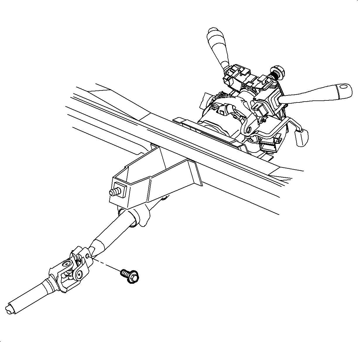
- Remove upper intermediate shaft bolt and disconnect shaft from steering column.
- Remove steering column lower support bolt.
- Remove steering column upper support bolt and nut.
- Remove steering column from vehicle.
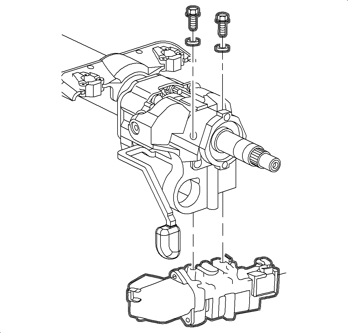
- Position steering column in a vise at upper bracket. Using a centering punch, mark the center of shear bolts on lock cylinder housing assembly.
- Drill a small hole (1/8 in. drill bit) in shear bolts at center mark. Remove shear bolts with a screw extractor, and remove ignition module and housing from steering column.
Notice: Cover driver seat to protect seat trim.
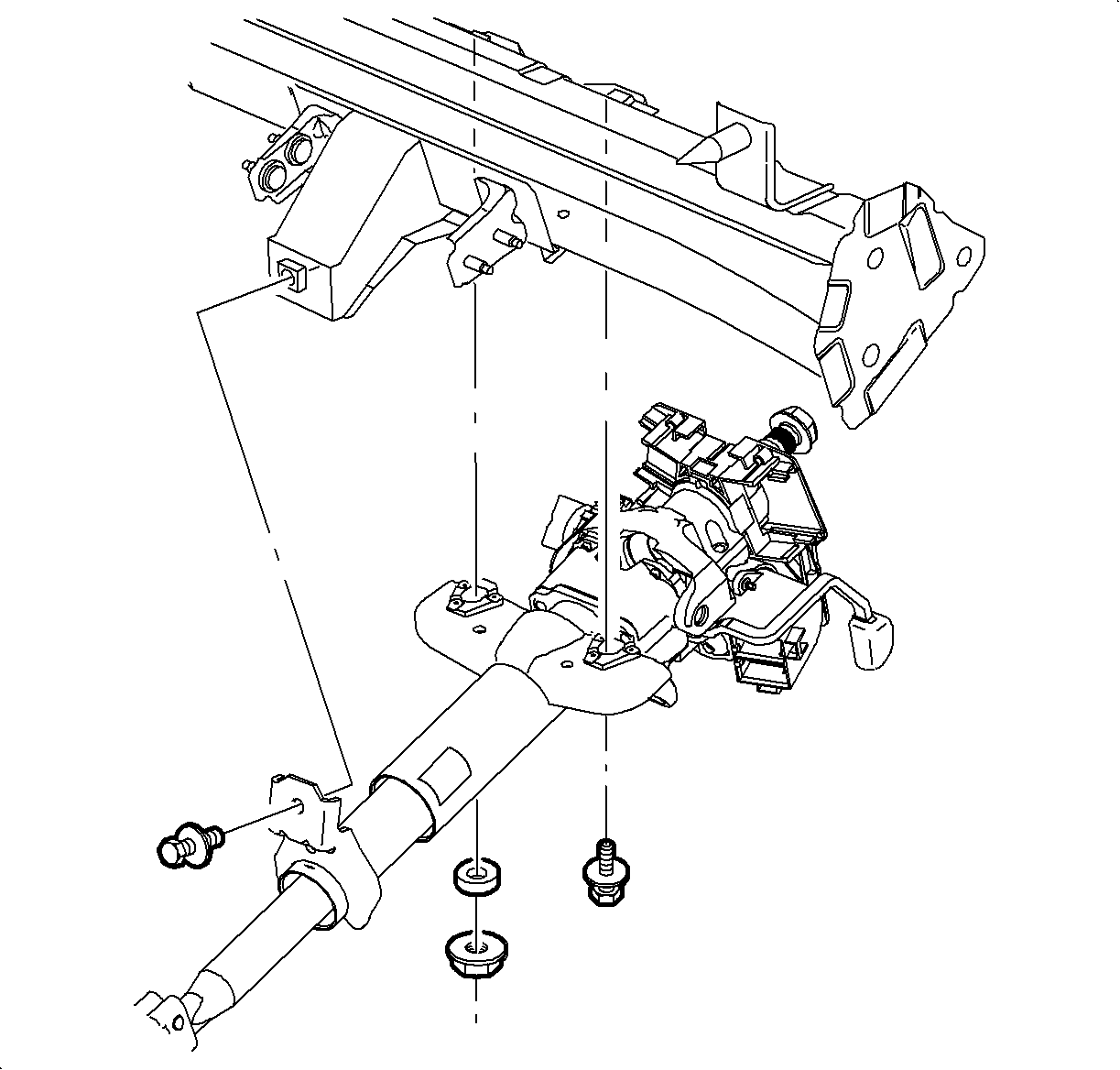
Important: Behind the nut is a plastic locator for steering column. This piece will center steering column in front of driver in the event of an accident.
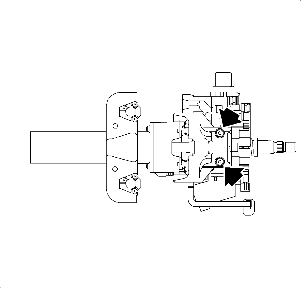
Important: The following steps are provided if replacing steering column.
Installation Procedure
- Use new shear bolts to install lock cylinder housing assembly on steering column. Torque shear bolts until heads break off.
- Carefully place the steering column in the vehicle.
- Install upper and lower steering column mount bolts and upper steering column mount nut along with locator.
- Connect intermediate shaft, install pinch bolt.
- Install signal switch housing to steering column.
- Install wiper/washer and headlamp/turn signal switch.
- Connect interlock solenoid electrical connector at bottom of steering column.
- Connect electrical at the wiper/washer switch and headlamp/turn switch.
- Connect ignition switch connectors at left side of column.
- Connect ignition switch connector at right side of column.
- Install knee bolster.
- Install HVAC duct.
- Install SIR coil assembly. Refer to Inflatable Restraint Steering Wheel Module Coil Replacement in SIR.
- Enable the SIR system. Refer to Enabling the SIR System in SIR.

Important: The following step is used if replacing steering column.

Important: The plastic steering column locator should be installed behind upper steering column mount nut. This locator centers steering column to driver in the event of an accident
Tighten
Tighten Steering Column-to-I/P Support Beam Fasteners to 30 N·m (22 lb ft).

Important: Use Loctite 242® Threadlocker (or equivalent) on thread of pinch bolt.
Tighten
Tighten Intermediate Shaft Pinch Bolt to 30 N·m (22 lb ft).

Tighten
Tighten Signal Switch Housing-to-Steering Column Screws to 1.5 N·m (14 lb in).


