Identifying Refrigerant Purity

Notice: The purity of the system refrigerant should be confirmed before any other diagnostics
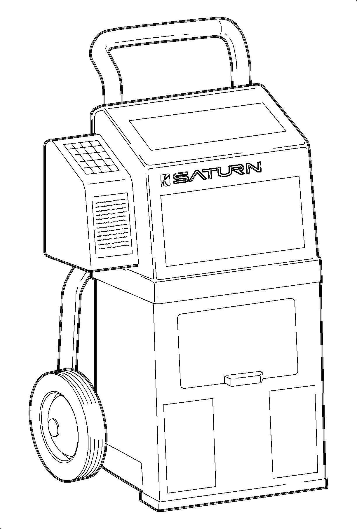
are begun. The RI-2002DS refrigerant identifier has the ability to identify R-12,
R134a, R-22, potentially dangerous hydrocarbons, and non-condensable gases (NCG) such
as air. If the A/C system contains anything less than 98 percent pure refrigerant,
the refrigerant is considered contaminated and the temperature/pressure charts will
not be valid. Contaminated refrigerant should not be recovered as it will contaminate
the recovery machine and refrigerant supply tank. Air is not considered a contaminate
as it can be purged.
- Turn ON refrigerant identifier and let it reach operating temperature
(3-5 minutes).
- When display reads "HOSE," and with the vehicle turned OFF, attach the
hose to the low side (suction) port and open service valves.
- Press ENTER button.
- The display will read GAS as a sample of refrigerant is taken and analyzed.
- When analysis is complete, display will show, by percentage, the make-up
of gases.
| • | If refrigerant is less than 98 percent pure, the temperature/pressure
charts will not be accurate for system diagnosis. |
| • | If refrigerant is pure but contains air, system should be recovered and
recharged with virgin refrigerant before proceeding. |
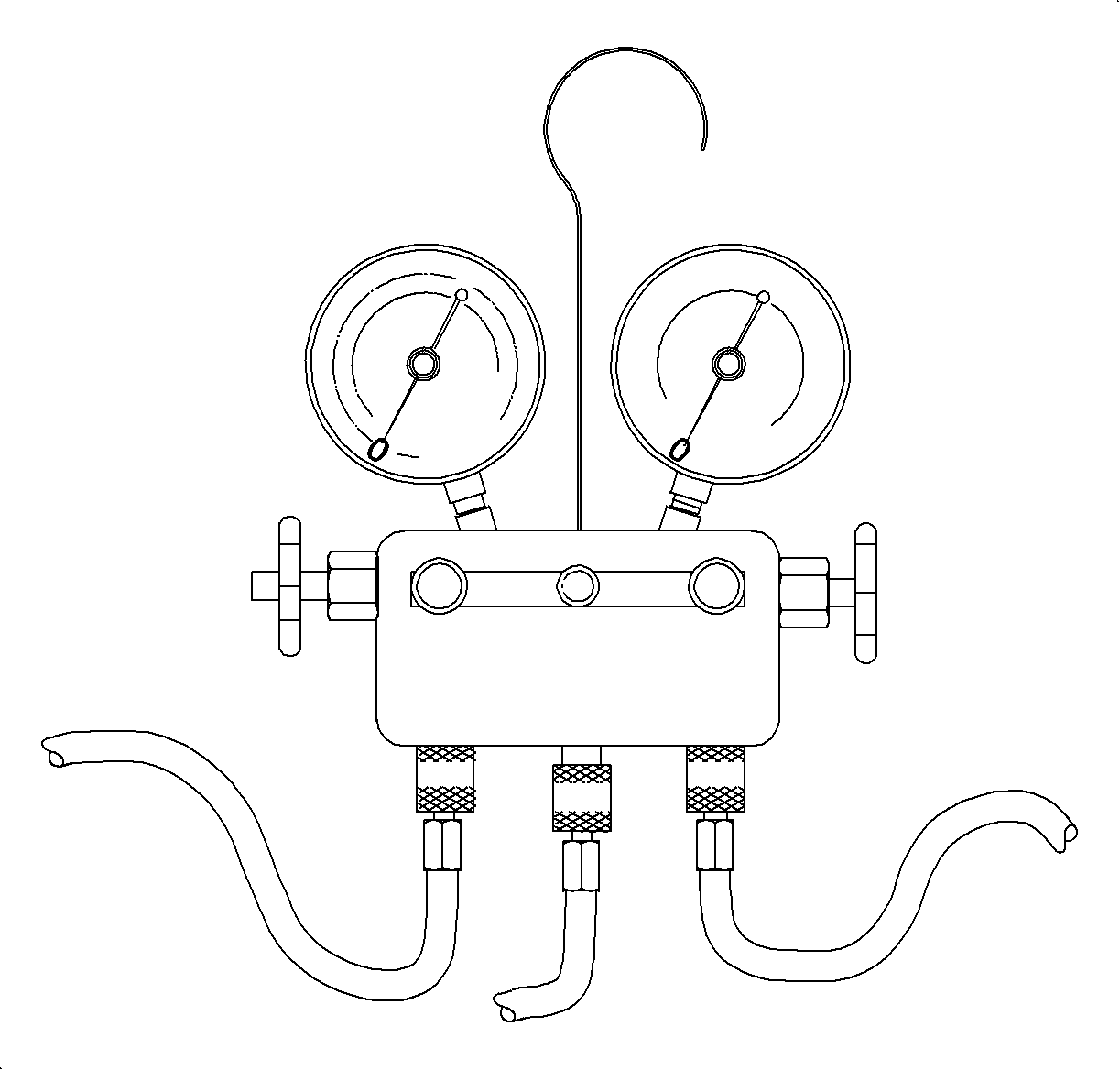
Installing Manifold Gage Set

If an A/C system problem still exists after you have completed the preliminary
checks, more diagnostic tests must follow. These include manifold gage set readings.
Follow the steps listed below for installing a manifold gage set.

Caution: Always wear goggles and wrap a clean cloth around fittings, valves, and connections
when performing work that involves opening the refrigerant system.
Important: Check to make sure gages read zero before installing manifold gage set.
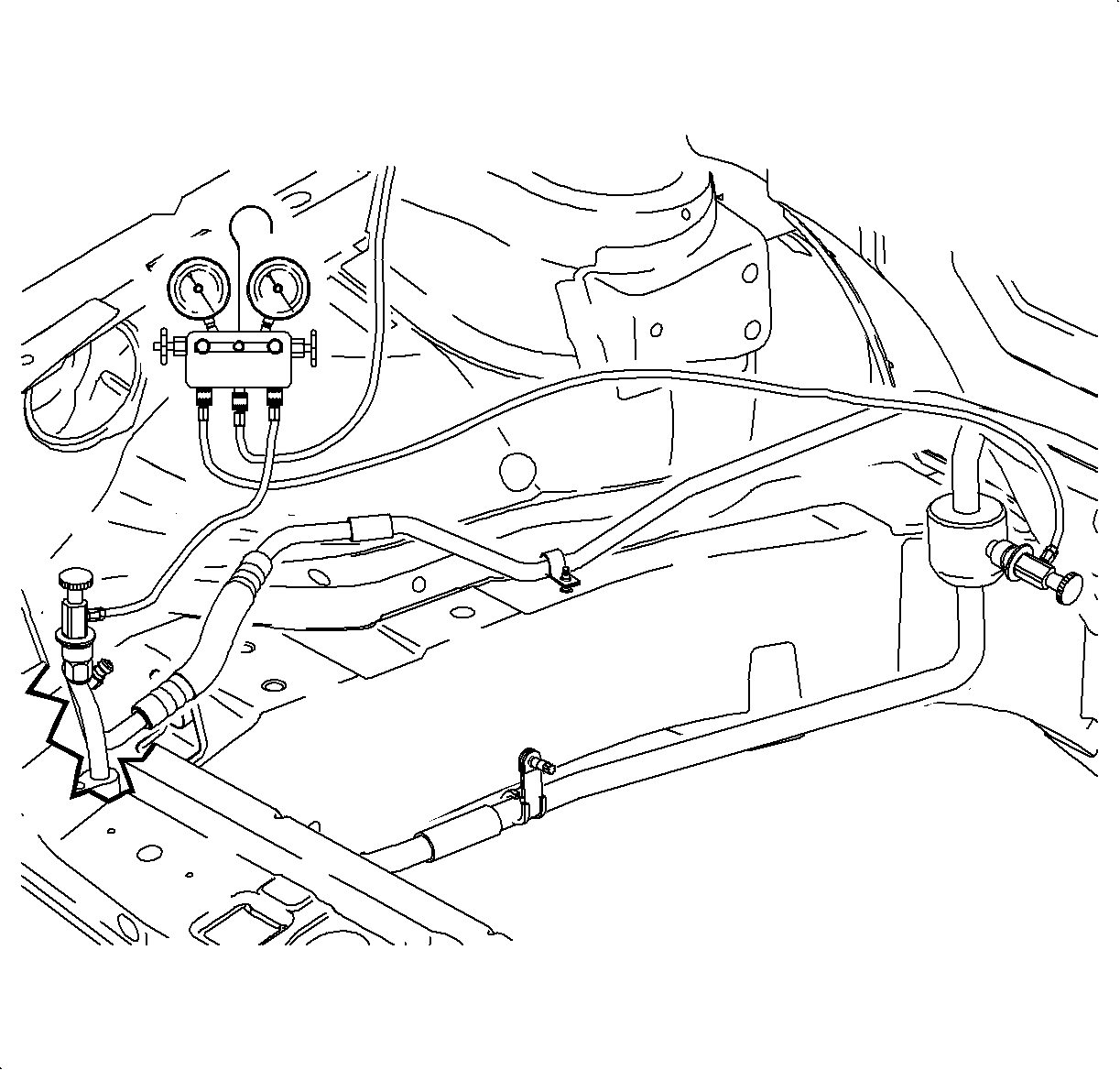
- Close both hand valves of manifold gage set.
- Connect low pressure (blue) gage hose to suction service port located
on the suction pipe muffler at inner right strut housing. Pull valve assembly collar
up, place valve assembly over service port and release collar.
- Open service valve.
- Connect high pressure (red) gage hose to discharge service port located
on the liquid line forward of air box. Pull valve assembly collar up, place valve
assembly over service port and release collar.
- Open service valve.
Performance Test - Service Stall

Important: If ambient air temperature is lower than 0° C (32° F), A/C compressor
will not be enabled.
Important: This test must be performed in a service stall environment that protects the
vehicle from wind that could cause incorrect pressure/temperature readings.
- Open hood and leave open during entire test.
- Install a manifold gage set to high and low side service ports.
- Start engine.

- Turn A/C OFF -
A/C button indicator light OFF.
- Depress re-circulation button so that indicator light is lit.
- Install thermometer into right center outlet.
- Set mode knob to I/P outlet position - full counter-clockwise.
- Set temperature knob to full cold position - full counter-clockwise.
- Set blower to third speed - M2.
- Open both front doors and windows to stabilize interior air temperature
with outside ambient temperature.
- Start engine and allow engine coolant temperature (ECT) to reach 86°C
(188°F).
| 1. | Turn A/C ON, using the console button. |
| 2. | Using Scan tool, command FAN CONTROL 2 ON, which will run both cooling
fans at medium speed. |
| 3. | Using accelerator pedal, increase engine speed to 2,000 rpm and hold. |
| • | Using Scan tool, perform HVAC PERFORMANCE test using an engine speed of 2,000
rpm. This test will command the A/C relay ON, turn the cooling fans on medium speed
and hold the engine speed to 2,000 rpm. |
Important: If the ECT is too high or the A/C high side pressure is too high, the engine
control module (ECM-L81) or powertrain control module (PCM-L61) will override the
fan control request and the cooling fans will be commanded on high.
- Record A/C system pressures and outlet temperature every minute for five minutes.
- Exit out of the scan tool test and return engine to idle.
- Release Tech 2 control of engine cooling fans.
- Compare recorded values to system performance charts then continue down
diagnostic flow chart.
Performance Test - 72 Km/h (45 Mph) Road Test

- Install a manifold gage set to high and low side service ports and route hoses
so that gages can be read from inside vehicle with hood closed.
- Start engine.
- Turn A/C OFF - A/C button indicator light OFF.
- Select outside air - re-circulation button indicator light is OFF.
- Install thermometer into right center outlet.

- Set mode knob to
I/P outlet position - full counter-clockwise.
- Set temperature knob to full cold position - full counter-clockwise.
- Set blower to third speed - M2.
Important: A Tech 2 with version 19.005 or higher software is required to perform this
test.
- Connect Tech 2 to data link connector (DLC).
- Using the Tech 2, verify engine is operating at thermostat control temperature
- ECT is 188° F or greater.
- For L81 engines use the appropriate Tech 2 special function to set engine
cooling fan speed to medium.
| 11.1. | Select Fan Control 1 and press enter. |
| 11.2. | Command fan control ON. Display should indicate fans are operating at
MED. |
| 11.3. | Turn A/C ON - A/C button indicator light ON. |
- For L61 engines use the appropriate Tech 2 special function to set engine
cooling fan speed to medium.
| 12.1. | Select HVAC Performance special function and press enter. Display should
indicate fans are operating at MED. |
| 12.2. | Turn A/C ON - A/C button indicator light ON. |
Important: Allow A/C system pressures to stabilize before beginning test.
- Drive vehicle at 72 km/h (45 mph).
- Record A/C system pressures and outlet temperature every minute for 5
minutes.
- Release Tech 2 control of engine cooling fans.
- Compare recorded values to system performance charts then continue down
diagnostic flow chart.


