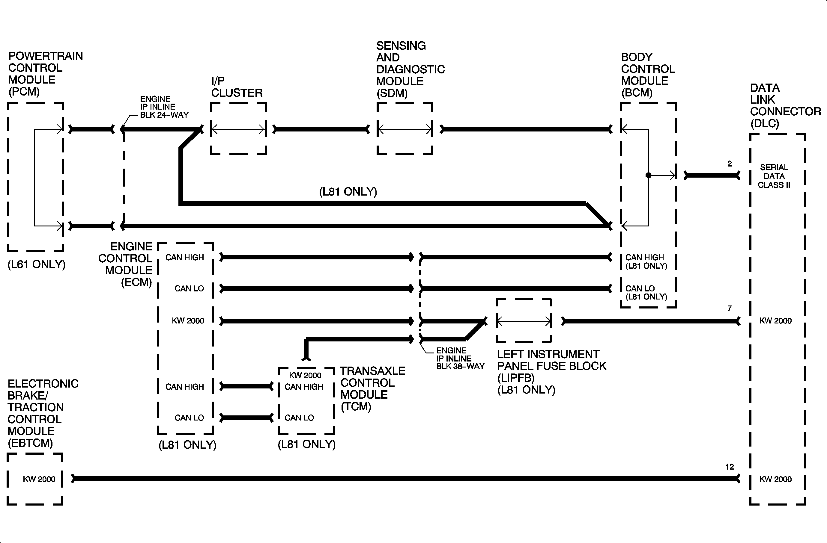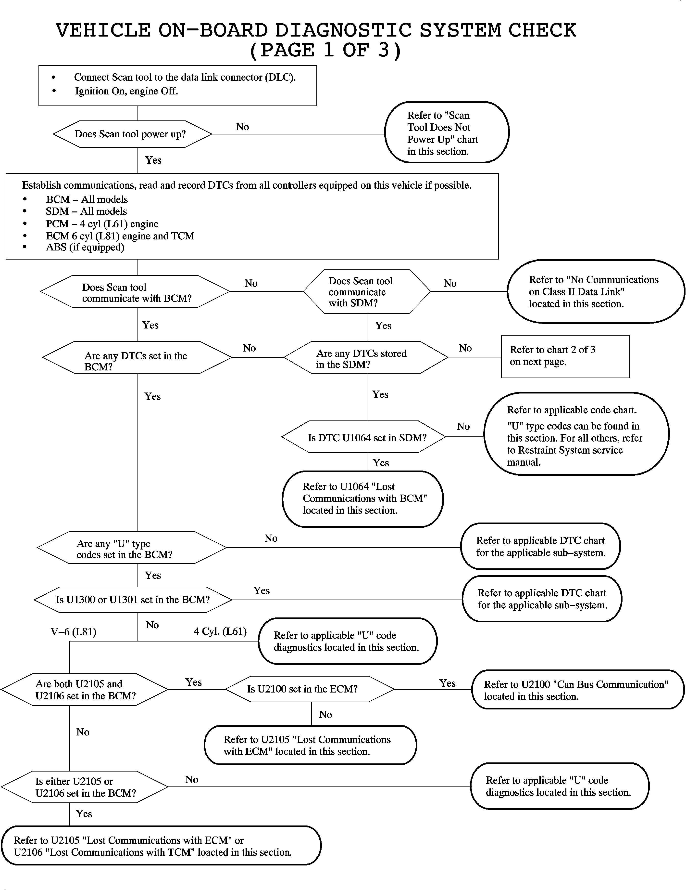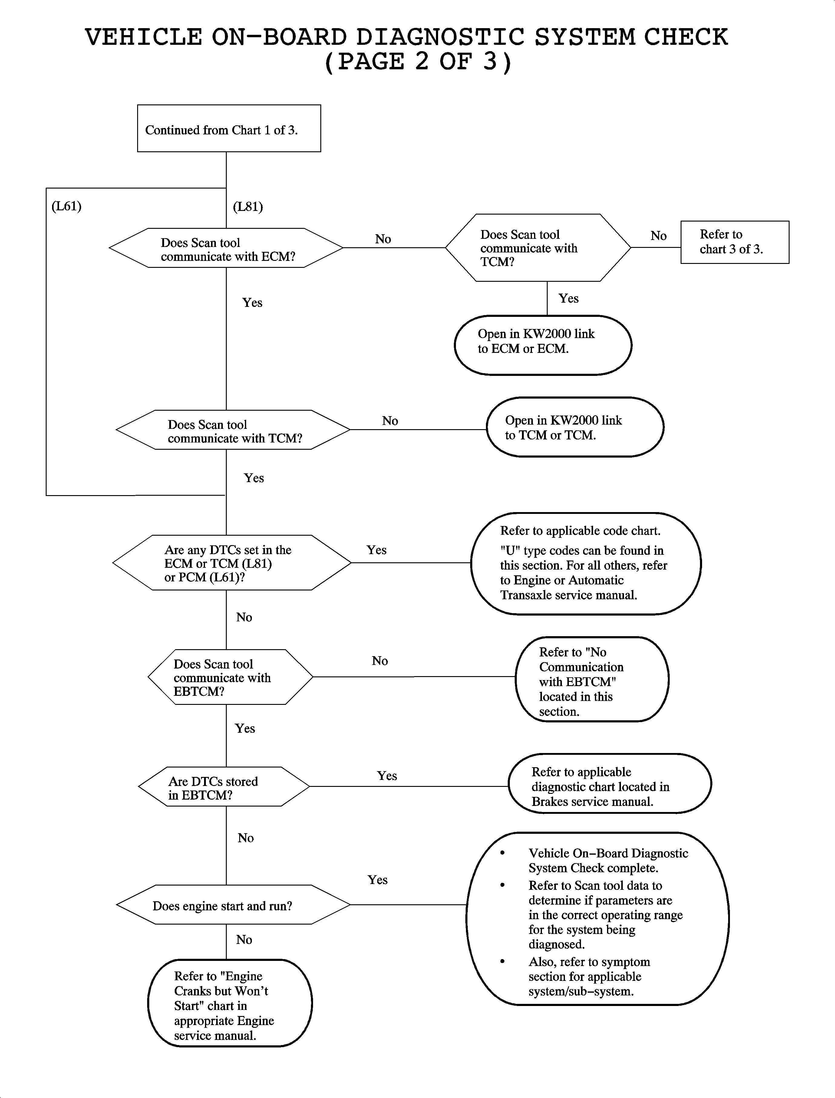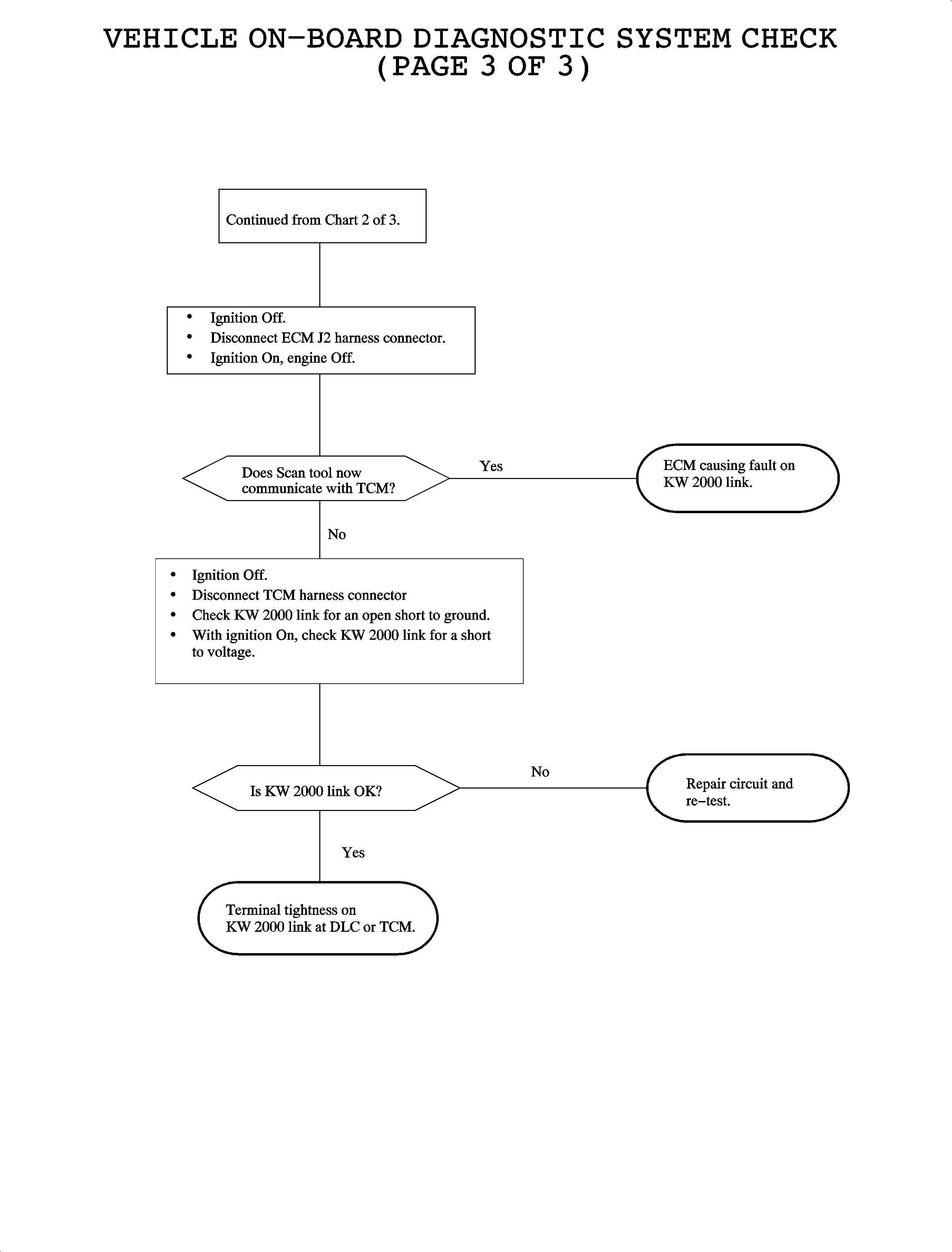
The vehicle on-board diagnostic system check should always be the starting point when diagnosing any powertrain, chassis, or any other electrical sub-system. This is important due to the amount of systems that are controlled by an electronic module. Also, associated with the increased functions of these modules comes more on-board diagnostics resulting in diagnostic trouble codes (DTCs). Many controllers share the same power or ground circuits as other sub-systems, therefore there may be a DTC in a controller that appears unrelated to the customer complaint. Checking for DTCs is also important since all DTCs do not result in a warning telltale being illuminated.
Regardless of the customer complaint/symptom, it is important to establish serial data communications with each controller, read codes from each controller, and record the information gathered. It is important to start with the BCM because:
- The body control module (BCM) is the closest module to the data link connector (DLC).
- The BCM is the data link master and is capable of detecting when another module on the Class II link or the CAN link is missing. When the BCM detects a controller missing, a U-Type DTC will be stored in the BCM.
When communications cannot be established with the BCM, communications with the SDM should be the next step. This will help determine if a serial data link fault exists or if an individual module is not capable of communicating.
Since the BCM is the master on the Class II link and the SDM is on every vehicle, these controllers should be communicated with first since they may help to determine potential serial data link errors.
This chart continues establishing communications with each of the applicable modules on the vehicle.
The L61 engine and transaxle are controlled by a powertrain control module which communicates on the Class II link. The L81 engine and automatic transaxle communicates with the scan tool over a KW 2000 data link. Also, the electronic brake/transaction control module (EBTCM) communicates over a KW 2000 data link, but on a separate wire.
If communications can be established with each control module, and there are no DTCs associated with any module, the on-board diagnostics system check is complete. If no DTCs are detected, the next step is referring to the symptom section related to the customer complaint.
On the V6 L81 application, the scan tool communicates over a KW 2000 data link.
The BCM did not indicate any DTCs relating to the ECM or TCM, up to this point in the Vehicle On-Board Diagnostic System Check. Since the scan tool can not communicate with the ECM or TCM, this chart will diagnose faults associated with the KW 2000 data link.


