Disassembly Procedure
- Remove the park brake.
- Raise the vehicle on a hoist.
- Remove the rear wheel and the tire assembly.
- Remove the brake drum retaining screw.
- Remove the rear drum.
- Remove the upper return spring.
- Remove the upper return spring retaining bracket.
- Detach the adjuster lever and the spring.
- Pull the brake shoes apart slightly and remove the adjuster unit.
- Remove the brake shoe hold down springs and the pins.
- Remove the leading (front) brake shoe and the trailing (rear) brake shoe from the park brake cable.
- Disassemble the brake adjuster components: the adjusting socket, the screw, the clip, and the nut.
- Clean the adjusting socket, the screw, and the nut in clean denatured alcohol.
- Inspect the adjuster assembly, making sure that the adjuster screw threads smoothly into the adjusting nut, over the full threaded length.
- Inspect the wheel cylinder for leakage, cuts or damaged boots. Also, make sure that the wheel cylinder is not seized.
Caution: Ensure that the vehicle is properly supported and squarely positioned. To help avoid personal injury when a vehicle is on a hoist, provide additional support for the vehicle on the opposite end from which the components are being removed.
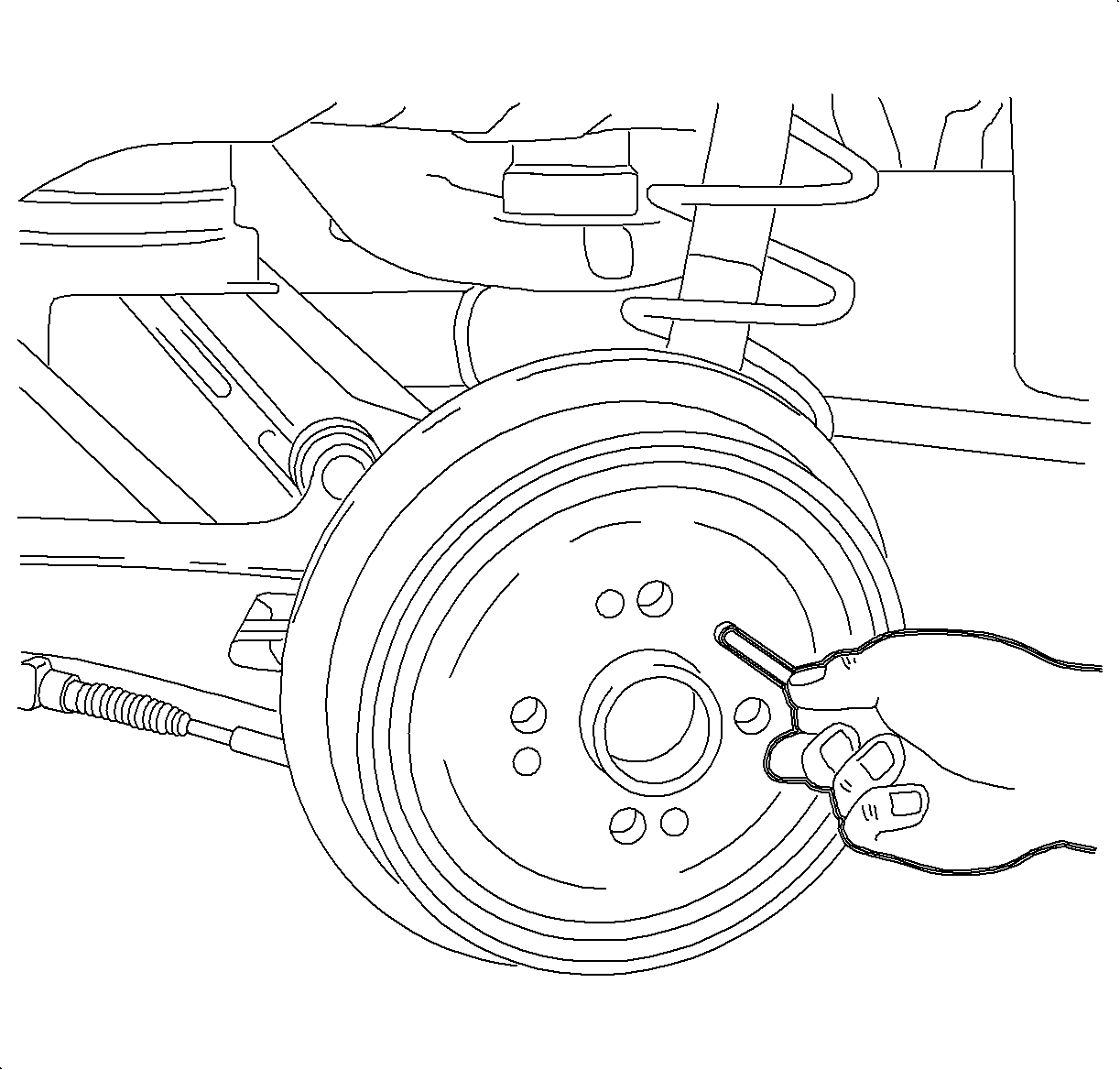
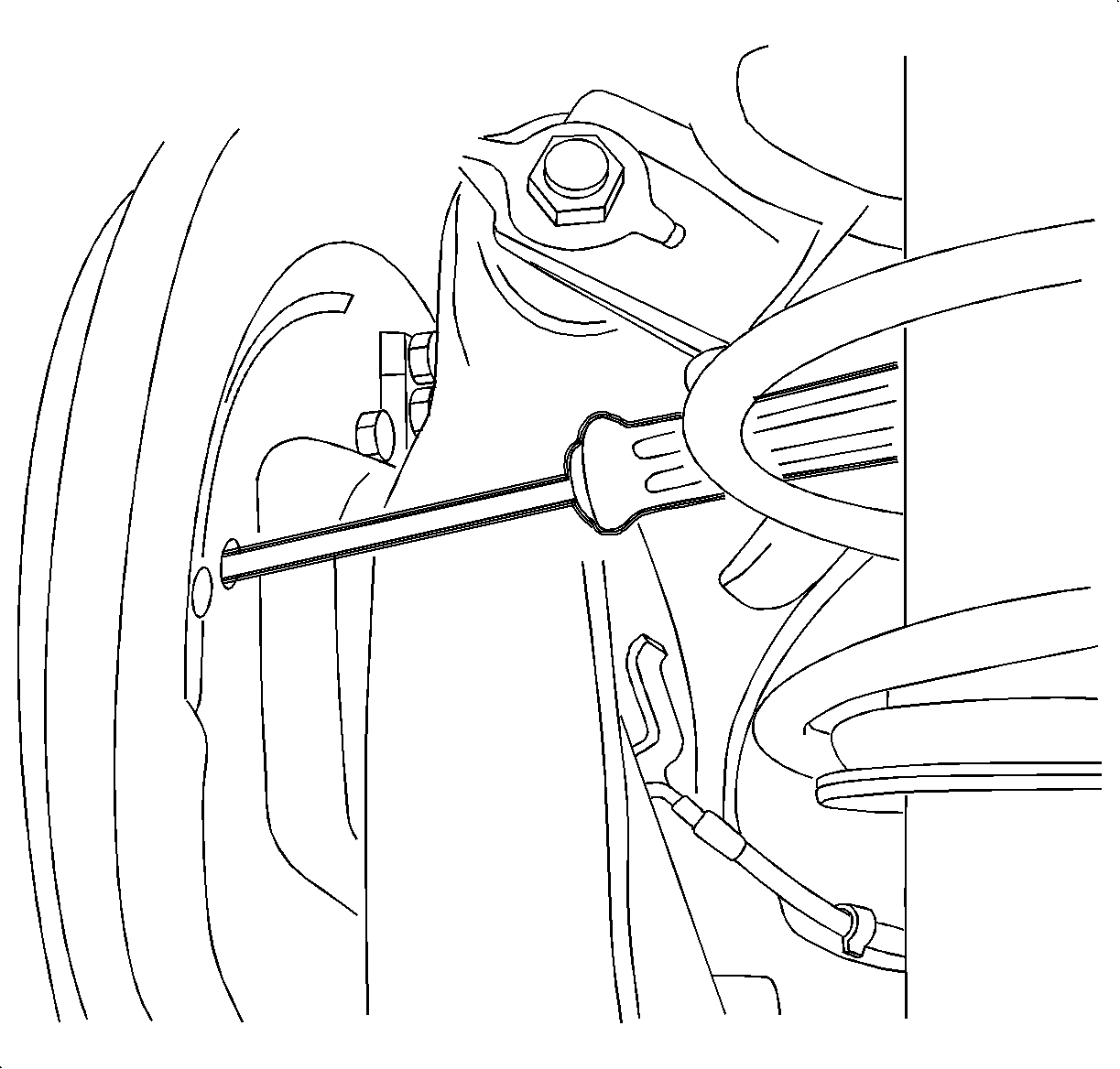
Notice: Do not pry against brake backing plate. This will bend plate.
| Important: If difficulty is encountered removing the drum, the following steps apply. |
| 5.1. | Insert a screwdriver in the access hole and push the park brake lever toward the outside of the drum to release the shoes from the adjuster. |
| 5.2. | Remove the brake drum. |
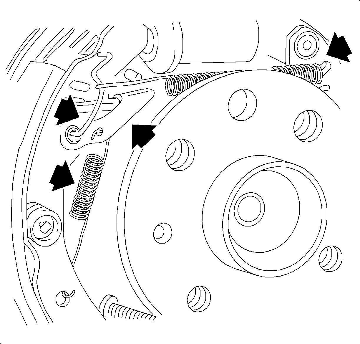
Notice: Do not over extend the springs. Over extending will weaken the springs.
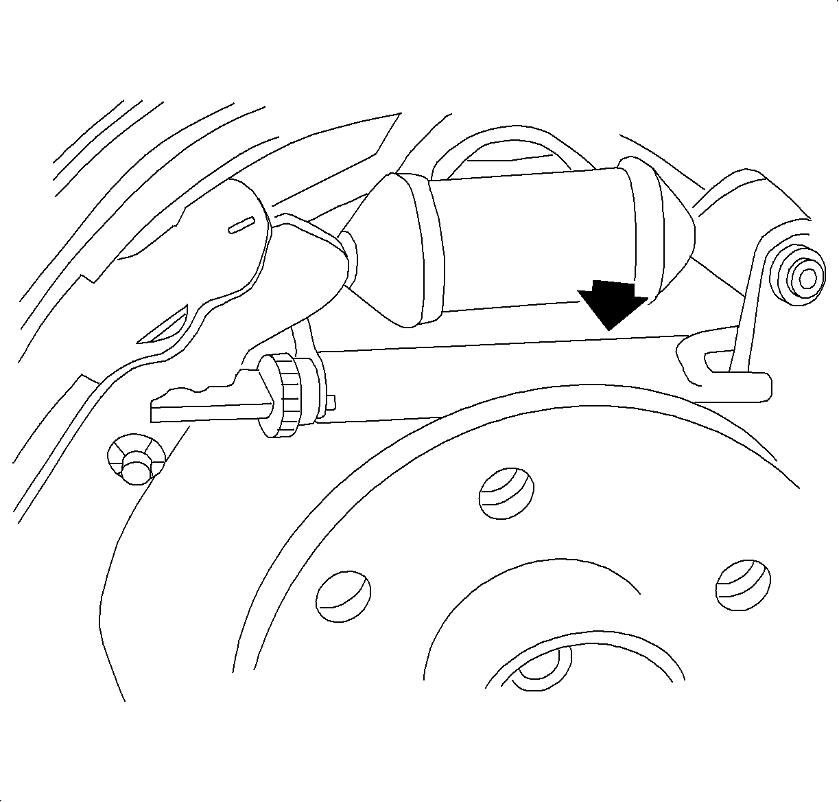
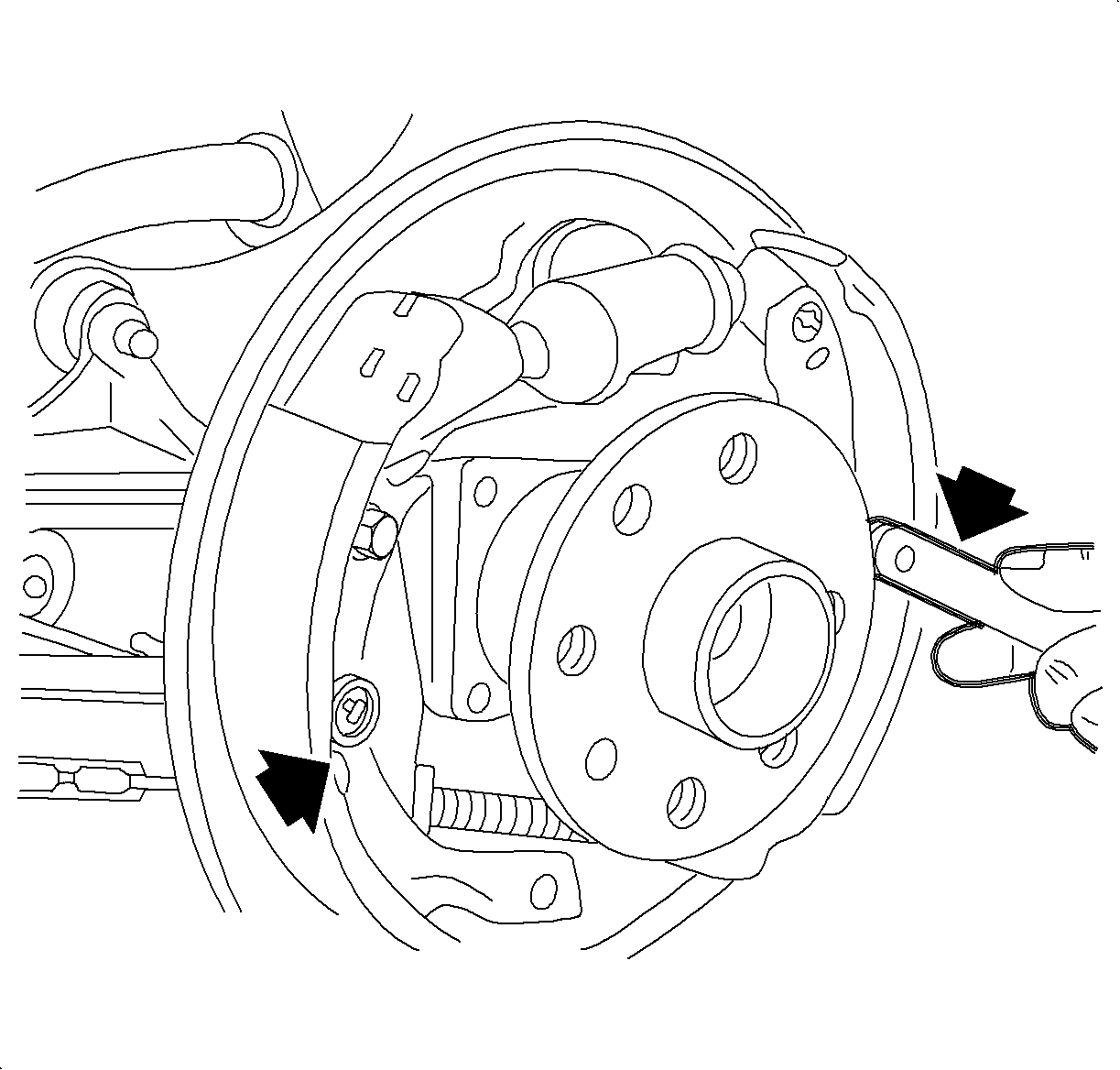
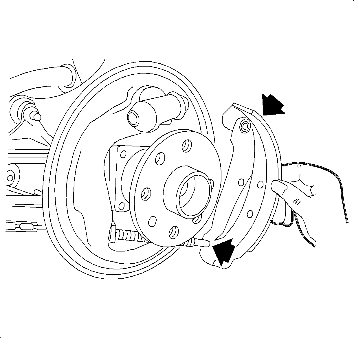
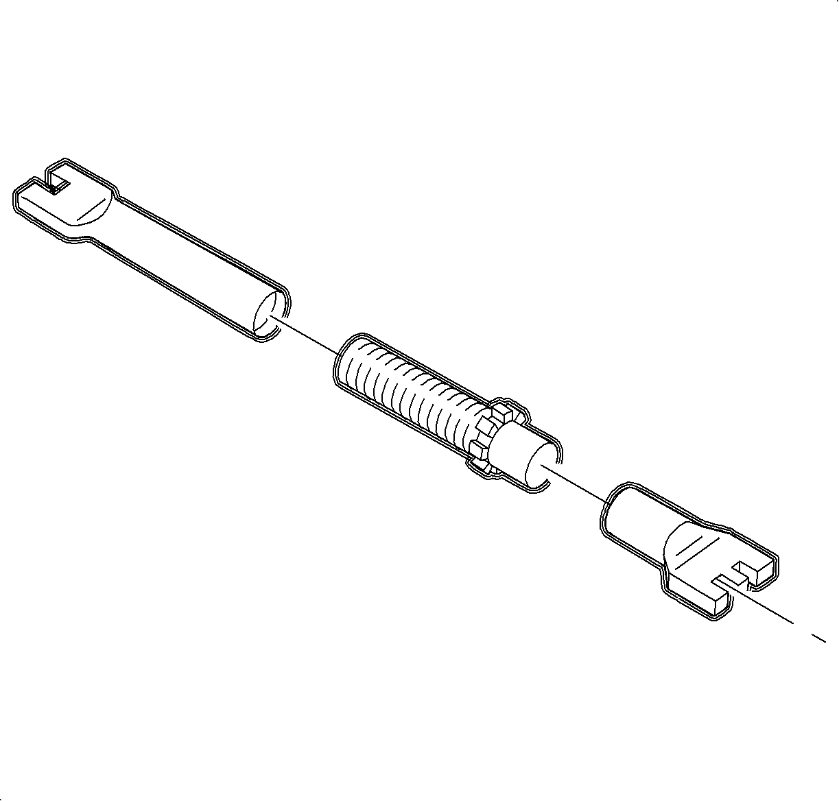
Notice: If wheel cylinder is found to be damaged, replace it. Do not attempt to repair wheel cylinder.
Assembly Procedure
- Lubricate the following components:
- Install the park brake cable to the park brake lever of the trailing (rear) brake shoe.
- Install the trailing (rear) brake shoe to the backing plate using the hold down pin and the retaining spring.
- Attach the lower retaining spring and install the leading (front) brake shoe, the hold down pin, and the retaining spring.
- Slightly pull apart the brake shoes and install the adjuster unit.
- Install the adjuster lever with the spring.
- Install the retaining bracket and install the upper return spring.
- Using a 165-368 mm (6.5-14.5 in) caliper such as the brake shoe setting gage or equivalent, measure the inside diameter of the brake drum.
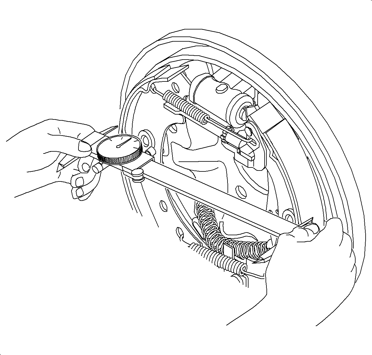
- Measure the outside diameter of the brake shoes and adjust the brake adjuster to obtain 0.50 mm (0.020 in) less than the reading obtained in the previous step.
- Install the brake drum and the retaining screw.
- Bleed the brakes if a new wheel cylinder or backing plate was installed. Refer to Rear Disc Brake Pads Replacement .
- Position the wheel and tire assembly onto the hub.
- Install the wheel bolts and tighten in a crisscross pattern.
- Lower the vehicle from the hoist.
- Apply and release the brake pedal 20 times to allow the adjuster to position the brake shoes.
- Adjust the park brake cable. Refer to Park Brake Adjustment .
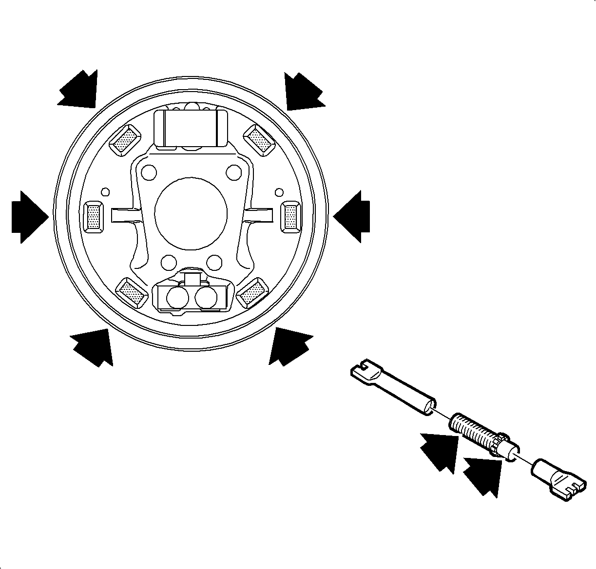
Important: When replacing the rear brake shoes, inspect the backing plate for excessive wear at the 6 raised shoe contact pads. Excessive wear at the raised shoe contact pads, such as notches or deep grooves, could impede shoe travel.
Important: Never replace the brake pads on one side of the axle only. The left and right side brake pads must be replaced only as axle sets.
| • | The adjuster lever surfaces that rub on the brake shoe web. |
| • | The backing plate at the 6 raised shoe contact pads. |

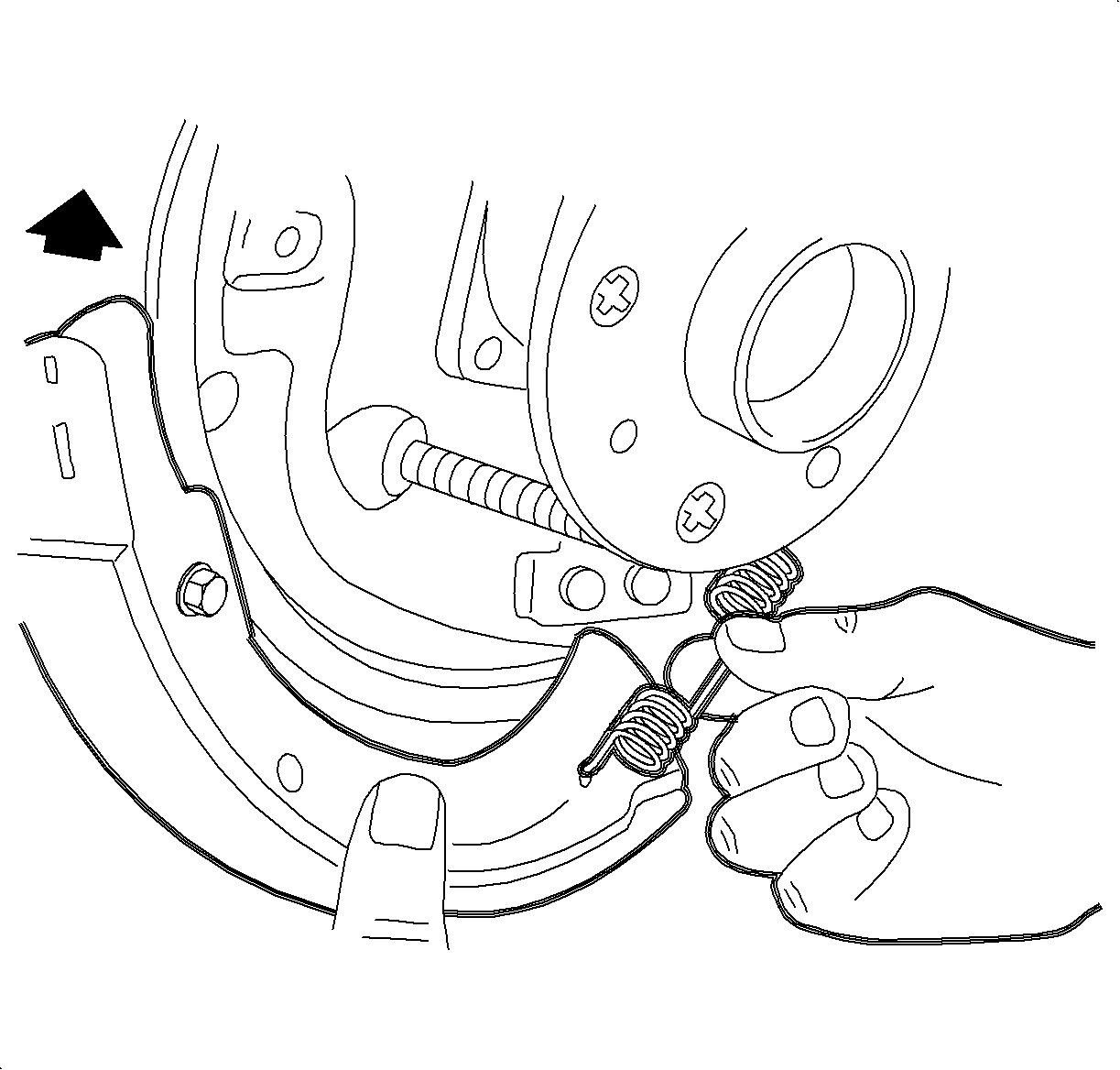


Important: Check that the brake shoe is correctly engaged in the wheel cylinder at the top and the anchor at the bottom.
Important: Check that the adjuster notches properly engage in the brake shoe notches.
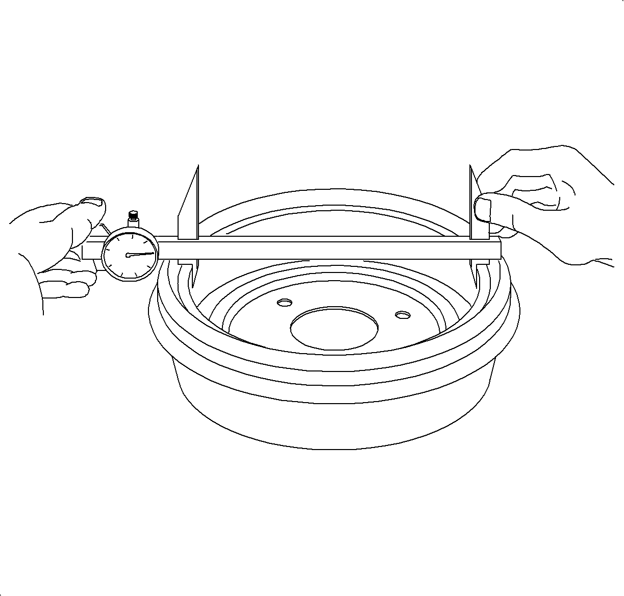
Important: Refer to Brake Rotor Surface and Wear Inspection .
Rear Drum Diameter
| • | New: 230.0 mm (9.05 in) |
| • | Maximum refinish/diameter: 230.65 mm (9.08 in) |
| • | Discard: 231 mm (9.09 in) |
Notice: Refer to Fastener Notice in the Preface section.
Tighten
Tighten the brake drum retaining fastener to 4 N·m (35 lb in).
Notice: Before installing wheels, remove rust or corrosion from wheel mounting surfaces and brake rotors/drums. Failure to do so can cause wheel nuts to loosen in service.
| 13.1. | Hand tighten all 5 wheel bolts. |
| 13.2. | Use a torque wrench to tighten the wheel bolts using a crisscross pattern. |
Tighten
Tighten the wheel bolts (initial torque) to 63 N·m (46 lb ft).
| 13.3. | Use a torque wrench to final tighten the wheel bolts using a crisscross pattern. |
Tighten
Tighten the wheel bolts (final torque) to 125 N·m (92 lb ft).
Caution: Prior to operating vehicle, depress brake a few times. If this operation is not carried out, brakes will not operate during initial brake applications and may cause an accident resulting in personal injuries.
