Tools Required
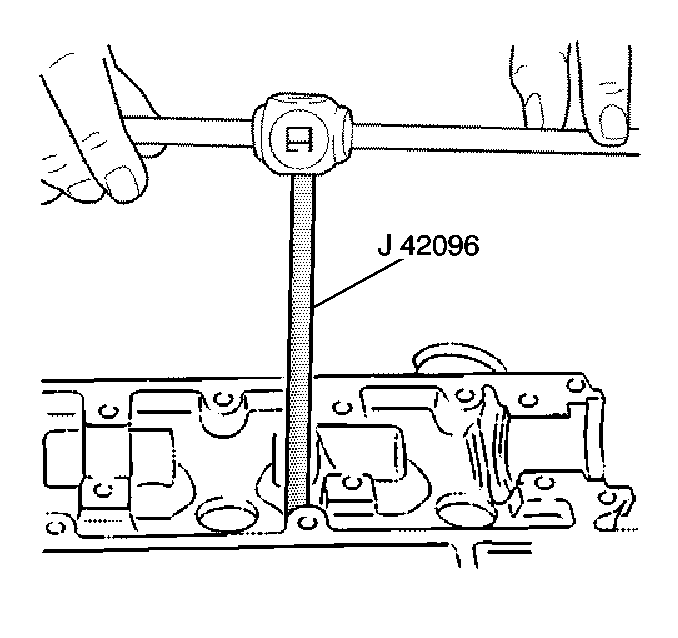
J 42096 Valve Guide
Reamer
Valve Guide Reaming Procedure

- Perform the following
steps to inspect the valve stem-to-valve guide clearance:
| 1.1. | Clamp the J 8001
on the exhaust port side of the cylinder head. |
| 1.2. | Locate the indicator so that the movement of the valve stem from
side to side (crosswise to cylinder head) will cause a direct movement of
the dial indicator stem. |
| 1.3. | Measure the valve head with the valve protruding 10 mm
(0.39 in) from the seat. |
| 1.4. | Drop the valve head about 10 mm (0.393 in) off the
valve seat. |
| 1.5. | Use light pressure to move the stem of the valve from side to
side to obtain a clearance reading. |
| 1.6. | The intake valve clearance should be 0.030 - 0.057 mm
(0.0011 - 0.0022 in). |
| 1.7. | The exhaust valve clearance should be 0.040 - 0.067 mm
(0.0015 - 0.0026 in). |
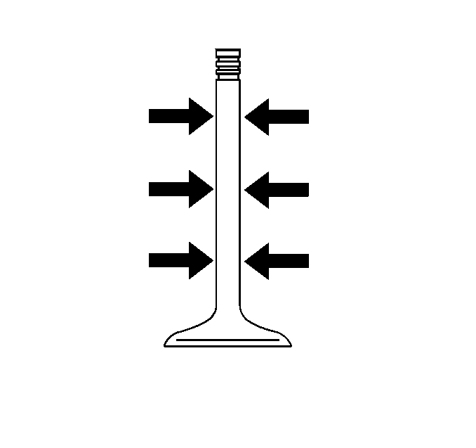
- If the valve clearance is out of specifications, measure the valve
stem in three locations shown in the illustration.
- Compare the lowest measurement to the specifications below:
| • | Intake valve stem: 5.955 - 5.970 mm
(0.2344 - 0.2350 in). |
| • | Exhaust valve stem: 5.945 - 5.960 mm
(0.2340 - 0.2346 in). |
- If the valve stem diameter is out of specification, replace the
valve.
- If the valve stem is within the specifications, the valve guide
is worn.
| • | The valve guide can be reamed oversize. |
| • | If the valve guide is reamed oversize, an oversize valve must
be installed. |

Important: An oversize valve will be required, after reaming the guide with J 42096
.
- Perform the following steps for reaming the valve guide:
| 6.1. | Clean the valve guide thoroughly. |
| 6.2. | Insert J 42096
into the valve guide from the top side of the cylinder head. |
| 6.3. | Apply light hand pressure while turning the reamer until the reamer
is all the way through the valve guide. |
| 6.5. | Clean the valve guide of all metal shavings. |
| 6.6. | Clean the cylinder combustion chamber of all metal shavings. |
Valve and Valve Seat Grinding Procedure
Tools Required
| • | J 8062 Valve
Spring Compressor |
Seating of the valves must be perfect for engine assembly to deliver
optimum power and performance. Another important factor is the cooling of
the valve heads. Good contact between the valve face and valve seat is
necessary to insure proper heat dissipation.
Valve guide bores must be free from carbon and/or free from dirt to
ensure proper centering of the pilot in the guide. Carefully follow the equipment
manufacturer recommendations to attain proper valve seat angles.
Valves that are slightly pitted can be refaced. Replace valves that
have excessive stem wear. Replace valves that are warped. Replace the valve
if the edge of the valve head is less than 1.6 mm (0.0625 in)
thick after grinding.
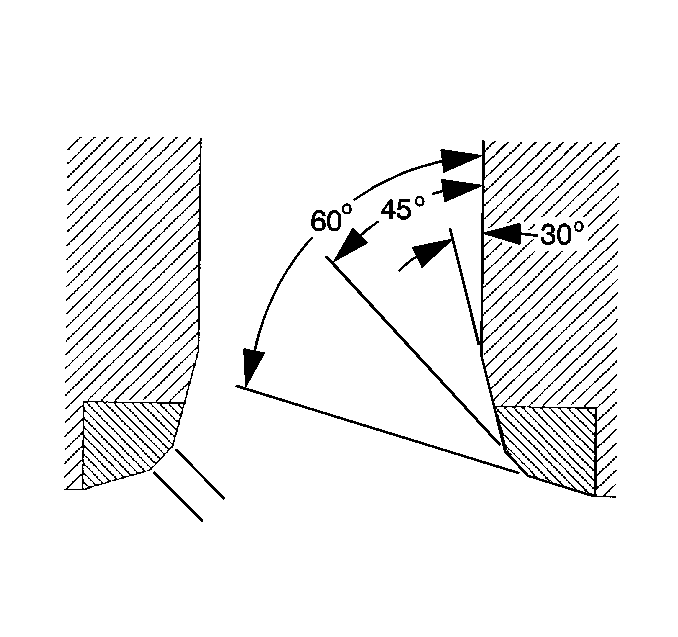
Use a 30 degree and a 60 degree stone to control valve
seat width.
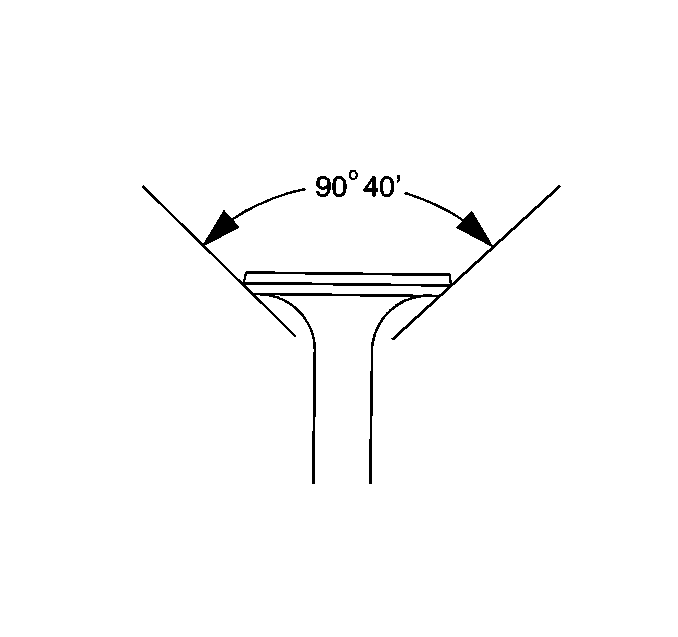
Grind the valves at a 90 degree 40 minute angle. Grind
the valve seat at a 90 degree angle. The 40 minute difference
in angles provides better sealing. The valve seat width should
be:
| • |

The intake valve seat
width should be 1.0 - 1.4 mm (0.039 - 0.055 in). |
| • |

The exhaust valve seat
width should be 1.4 - 1.8 mm (0.055 - 0.070 in). |


