SMU for 2000/2002 L Series Chassis Service Manuals Regarding Alignment Specifications and Service Procedure for Installation of Spacers between Rear Suspension Support and Vehicle Body

| Subject: | Service Manual Update for 2000/2002 L-Series Chassis Service Manuals Regarding Alignment Specifications and Service Procedure for Installation of Spacers between Rear Suspension Support and Vehicle Body when Performing Wheel Alignment. Due to the addition of a spacer installation service procedure, revised alignment specifications and 2002 model year vehicles, this bulletin has been revised and supersedes bulletin 00-T-72, which should be discarded. |
| Models: | 2000 - 2002 Saturn L-Series vehicles built up to and including VIN 2Y600704 |
Purpose
The purpose of this bulletin is to provide a service procedure for installing spacers between the rear suspension support and body of vehicle when performing a wheel alignment. Also provided in this bulletin are new alignment specifications.
Service Procedure
Spacer Installation
TOOLS REQUIRED
| • | KM-900 Rear Toe Adjusting Tool |
| • | SA9140E Torque Angle Gauge |
Caution: MAKE SURE VEHICLE IS PROPERLY SUPPORTED AND SQUARELY POSITIONED ON THE HOIST. TO HELP AVOID PERSONAL INJURY WHEN A VEHICLE IS ON A HOIST, PROVIDE ADDITIONAL SUPPORT FOR THE VEHICLE ON THE OPPOSITE END FROM WHICH COMPONENTS ARE BEING REMOVED.
- Raise vehicle on hoist.
- Remove rear wheel and tire assemblies
- Remove rear suspension lower control arm to rear axle control arm attachment bolts, discard bolts and nuts.
- Support rear suspension support with a suitable support stand.
- Remove the four rear suspension support to body bolts and discard bolts.
- Lower rear suspension support.
- Transfer washers from old bolts to new 137 mm (5.39 in.) longer bolts (10 mm longer than the original bolts). Insert bolt with washer from bottom of rear suspension support and place spacer between the top of support bushing and vehicle body. Hand start all 4 bolts before torquing any of the bolts.
- Using a die grinder (or equivalent), remove material from the lower control arm-to-knuckle location to make a slot. Remove material from the inboard side of the hole to make camber more positive.
- Using new bolts and new nuts, install lower rear suspension lower control arm to knuckle. Tighten but do not torque at this time.
- Position wheel onto hub.
- Install wheel bolts and tighten in a star pattern.
- Lower vehicle from hoist.
- Perform vehicle alignment as specified in the applicable model year L-Series Chassis Service Manual, using the new steps and specifications outlined in this bulletin.
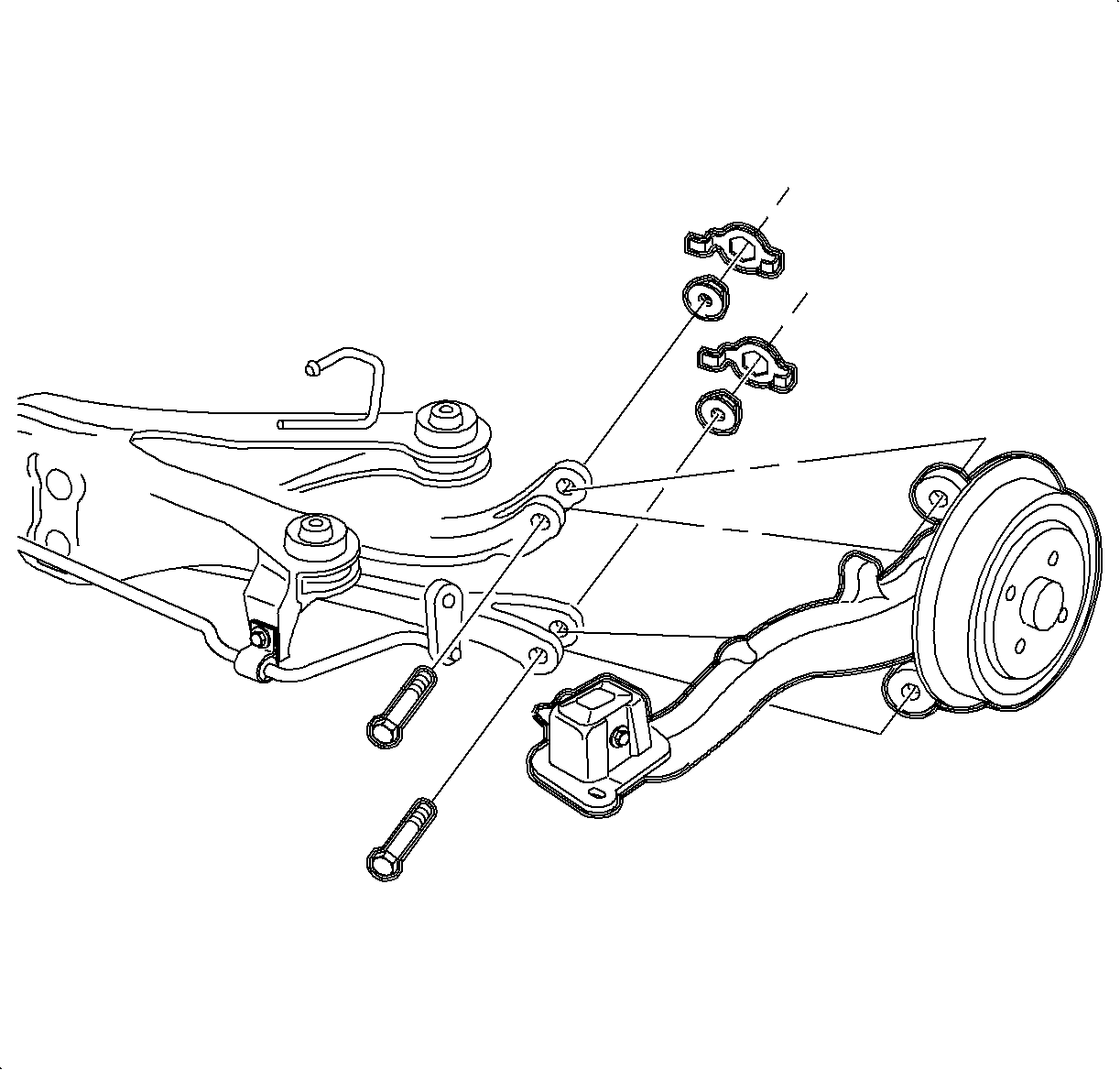
Important: Inspect for aftermarket shims between rear hubs and rear suspension trailing arms and remove if present.
Caution: SUPPORT THE FRONT OF THE VEHICLE TO ENSURE THAT THE VEHICLE WILL NOT BECOME UNBALANCED AND TIP FORWARD, OFF THE HOIST, ONCE THE REAR SUSPENSION SUPPORT IS REMOVED (DUE TO DECREASED PROPORTION OF REAR VEHICLE MASS). FAILURE TO SUPPORT FRONT OF VEHICLE COULD CAUSE VEHICLE TO FALL OFF THE HOIST.
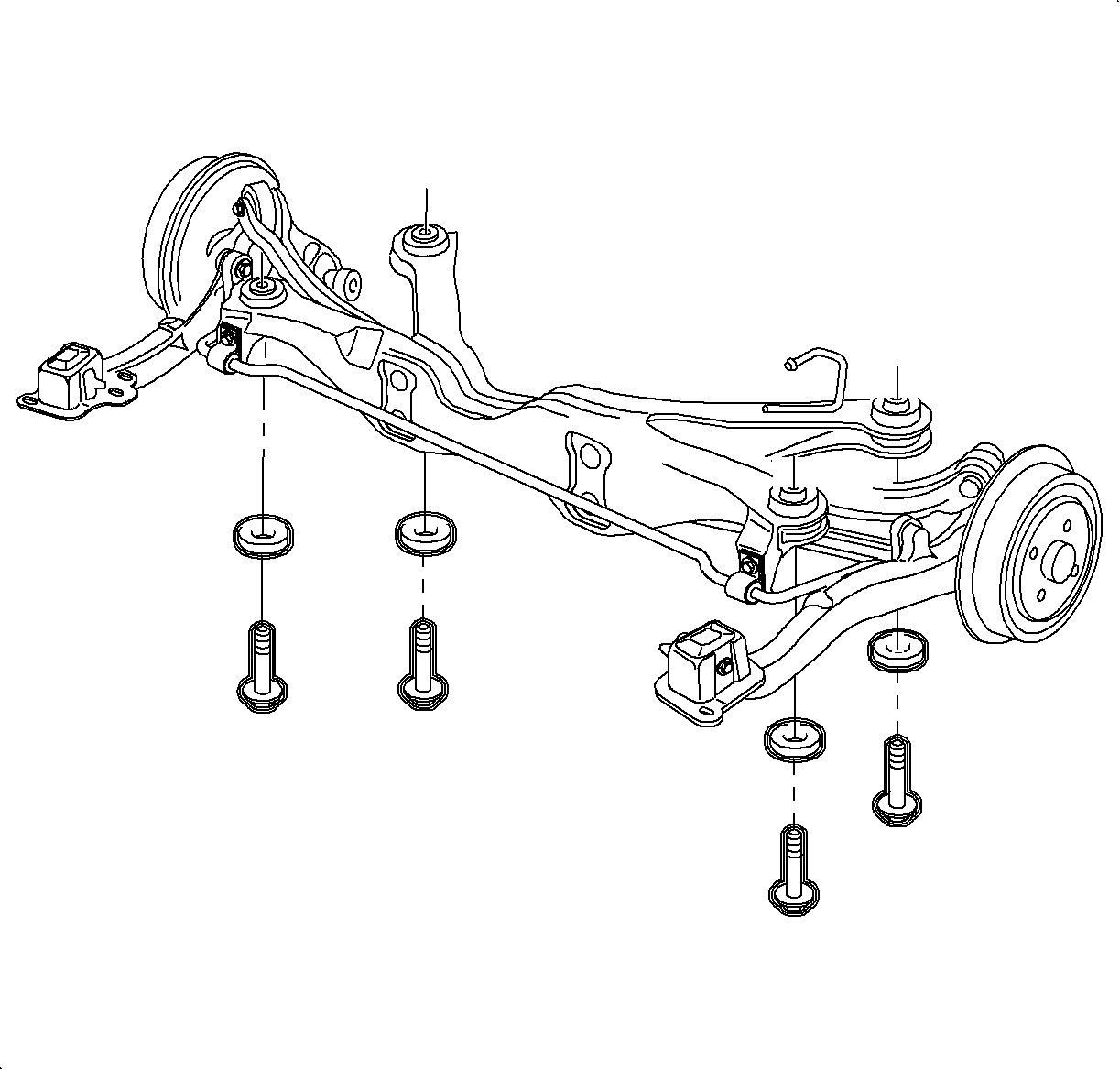
Tighten
Torque Rear Suspension Support-to-Body Bolts 90 N·m (66 ft lbs)
+ 90° to 105°.
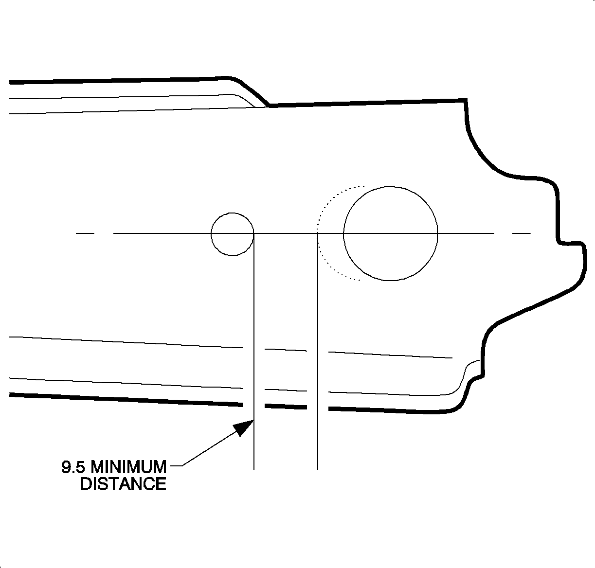
Important: The minimum distance between the inside of the slot and the adjacent hole is 9.5 mm.
Important: Paint exposed metal with primer after making slot.
Important: Do not use the control arm nut retainers since they will prevent adjustment of rear Camber.
Notice: Before installing wheels, remove rust or corrosion from wheel mounting surfaces and brake rotors. Failure to do so can cause wheel bolts to loosen in service.
| 11.1. | Hand tighten all five wheel bolts. |
| 11.2. | Use a torque wrench to tighten wheel bolts using a star pattern. |
Tighten
Torque Wheel Bolts Initial Torque 63 N·m (46 ft lbs).
| 11.3. | Use a torque wrench to final tighten wheel bolts using a star pattern. |
Tighten
Torque Wheel Bolts Final Torque 125 N·m (92 ft lbs).
Rear Alignment Procedure
Notice: Since rear camber will now be adjustable, and toe and camber setting impact each other, the following order of adjustment must be followed.
- Rear camber initial set
- Rear toe initial set
- Rear camber final set
- Rear toe final set
- Right front camber
- Left front camber
- Front toe
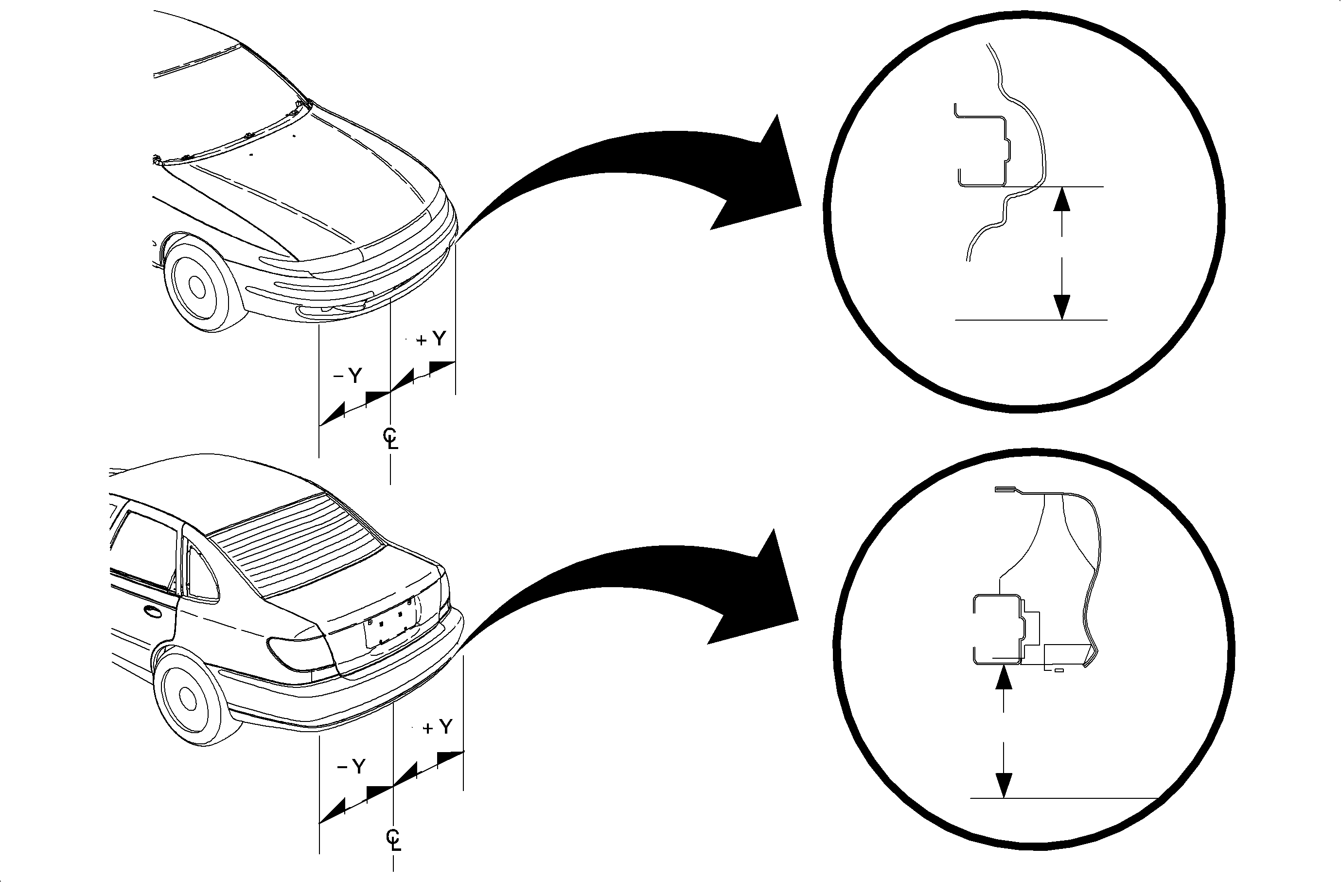
Important: When measuring alignment angles, it is critical that the vehicle bumper height be correct. Measure and adjust bumper height according to the following procedure before performing alignment.
- Place vehicle on a level surface.
- Adjust tire pressure to correct specifications.
- If vehicle fuel tank is not full, the following chart may be used to determine amount of weight necessary to be added to the trunk of vehicle to simulate a full fuel tank.
- Bounce front and rear of vehicle a few times to settle suspension.
- Measure front and rear vehicle curb trim height.
- After taking the initial rear camber reading, raise the rear of the vehicle.
- Loosen the rear lower control arm to knuckle bolt and move the knuckle in for more positive (+) or out for more negative Camber. It may be helpful to scribe around the bolt head as a reference before making adjustments.
- Tighten the rear lower control arm to knuckle bolt but do not torque at this time.
- Lower and jounce vehicle, then re-check Camber.
- Repeat steps 1 through 4 until camber is within 0.25 degrees of desired setting.
- Remove rear axle control arm bolts and cage nuts and discard.
- Install new bolts leaving the inside forward bolt out.
- Install Rear Toe Adjusting Tool KM-900, into the open bolt hole.
- Using Rear Toe Adjusting Tool KM-900, move rear axle control arm in the direction of necessary toe correction.
- Snug rear axle control arm bolts, do not tighten to final torque at this time.
- Recheck toe and adjust if necessary.
- When Rear Toe settings are within 0.10° of desired final settings, continue with next step.
- Recheck and, if necessary, adjust camber using steps 1 through 4 above.
- When Camber has reached desired setting, torque rear suspension lower control arm-to-knuckle bolt using the torque angle method and Torque Angle Gauge SA9140E (or equivalent).
- Recheck toe and adjust if necessary.
- Using Torque Angle Gauge SA9140E (or equivalent), tighten rear axle control arm bolts using the torque angle method.
- Repeat procedure for other rear wheel.
- Check front wheel alignment and adjust if necessary using the appropriate section of the applicable model year L-Series Chassis Service Manual.
- After alignment is completed print out or record final "Alignment Specifications" (alignment performed).
Curb bumper height should be measured with:
| • | 207 kPa (30 psi) tire pressure - front tires |
| • | 207 kPa (30 psi) tire pressure - rear tires |
Fuel Level -- Weight to Add
1/8 -- 31.8 kg (80 lbs)
1/4 -- 27.2 kg (70 lbs)
3/8 -- 22.7 kg (60 lbs)
1/2 -- 18.1 kg (45 lbs)
5/8 -- 13.6 kg (35 lbs)
3/4 -- 9 kg (20 lbs)
7/8 -- 4.5 kg (10 lbs)
MODELS -- ALL
FRONT -- 390 mm (15.35 in.)
REAR -- 530 mm (20.86 in.)
Measure curb bumper height from ground to bottom horizontal surface of bumper.
MODELS -- ALL
FRONT -- 395.3 +/- 25.0 mm (15.56 +/- 0.98 in.)
REAR -- 386.4 +/- 25.0 mm (15.21 +/- 0.98 in.)
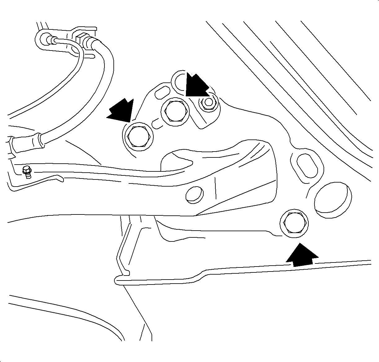
Notice: Use new bolts and cage nuts. Torque retention of old bolts and nuts may not be sufficient.
Important: Do not tighten bolts at this time.
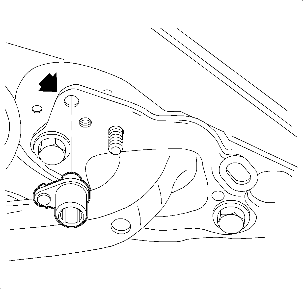
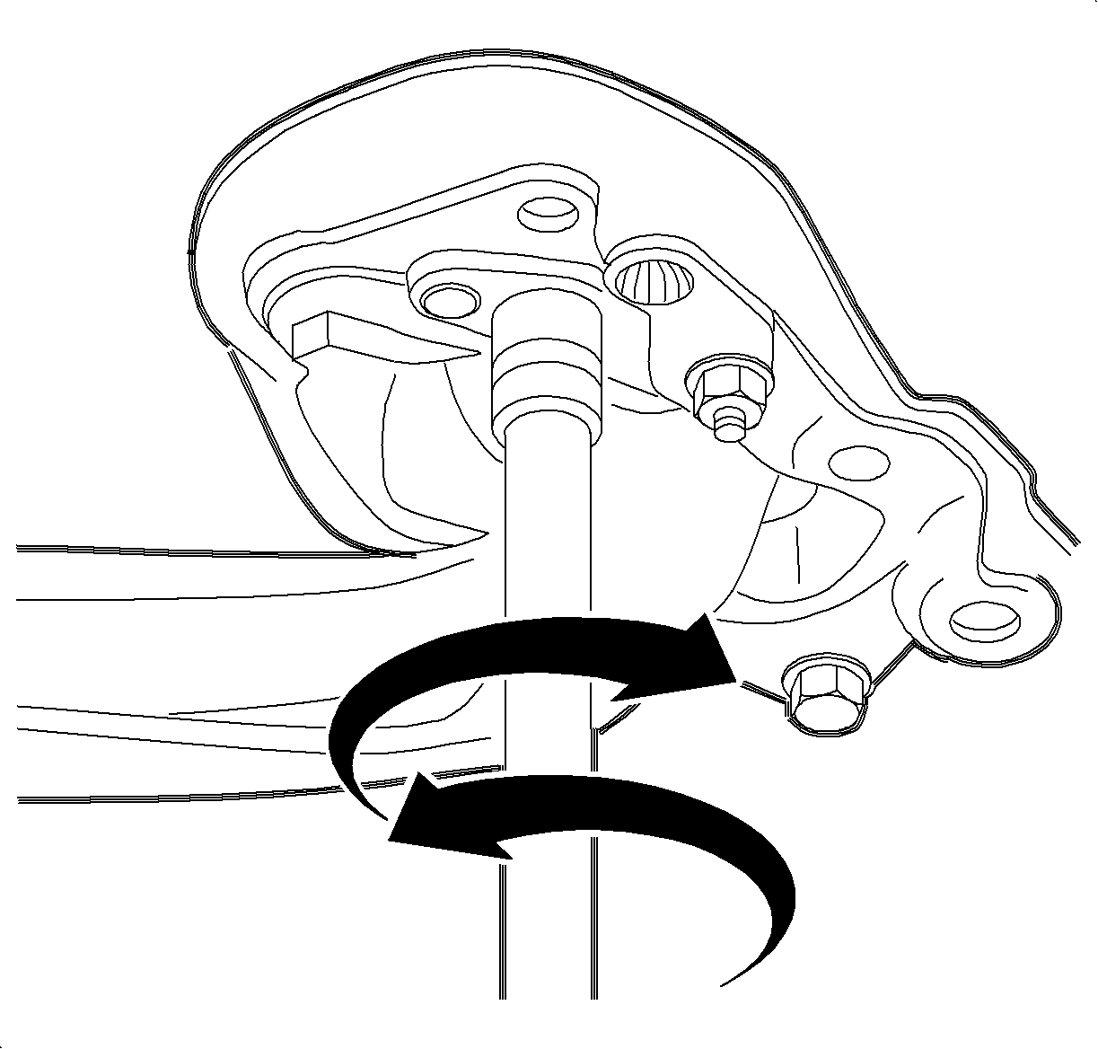
Tighten
Torque Rear Suspension Control Arm-to-Knuckle Bolt 90 N·m (66 ft lbs)
+ 60° to 75°.

Tighten
Torque Rear Axle Control Arm Bracket-to-Body Bolts 90 N·m (66 ft -lbs)
+ 30° to 45°.
(If an Alignment is Performed) | |||
|---|---|---|---|
FRONT | Preferred Setting (Degrees) | Minimum (Degrees) | Maximum (Degrees) |
Camber: | -1.00 | -1.75 | -0.50 |
Cross Camber | 0.00 | -1.00 | +1.02 |
Toe (Per Wheel) | +0.10 | +0.02 | +0.18 |
Total Toe: | +0.20 | +0.04 | +0.36 |
Caster is Not Adjustable | |||
Caster: | +3.70 | +2.70 | +4.20 |
Cross Caster: | 0.00 | -1.00 | +1.00 |
REAR | |||
Toe (Per Wheel): | +0.05 | +0.05 | +0.12 |
Total Toe: | +0.10 | +0.10 | +0.24 |
Caster is Not Adjustable | |||
Camber: | -0.50 | -0.50 | -1.00 |
Cross Camber: | 0.00 | -0.50 | +0.50 |
Shaded area signify new alignment specifications.
Parts Information
Part Number | Description | Quantity Required |
|---|---|---|
22699823 | Spacer-RR SUSP Support | 4 |
11588478 | Bolt/Screw RR SUSP | 4 |
90539298 | Bolt/Screw RR SUSP Cont Arm | 2 |
11094487 | Nut RR SUSP Cont Arm | 2 |
11519322 | Bolt/Screw RR SUSP KNU | 6 |
09231106 | Nut RR SUSP KNU | 6 |
Claim Information
To receive credit for this repair during the warranty coverage period, submit a claim through the Saturn Dealer System for E2020 (Wheel Alignment - Check or Adjust). An "add time" condition is provided to replace spacers in rear suspension support and for enlarging camber adjustment bolt holes in control arms.
