V6 (L81) Timing Belt Noise

| Subject: | V6 (L81) Timing Belt Noise |
| Models: | 2000 - 2001 Saturn L-Series vehicles equipped with L81 (V6) engines |
Condition
Some customers may comment about an unusual noise coming from the engine compartment. The noise may be described as a pigeon coo, or fluttering type noise.
Cause
A section of the timing belt between the number two (2) cam sprocket and the upper idler pulley oscillation causing noise.
Correction
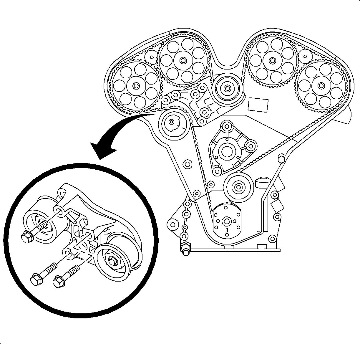
A new timing belt tensioner bracket changes the location of the upper idler pulley.
Service Procedure
TOOLS REQUIRED
| • | J42069 Timing Belt Alignment Kit |
| • | J42098 Crank Hub Torx Socket |
| • | J43405 Engine Support Fixture Adapter |
| • | SA9105E Engine Support Fixture (3 Bar) |
Removal
- Disconnect negative battery cable.
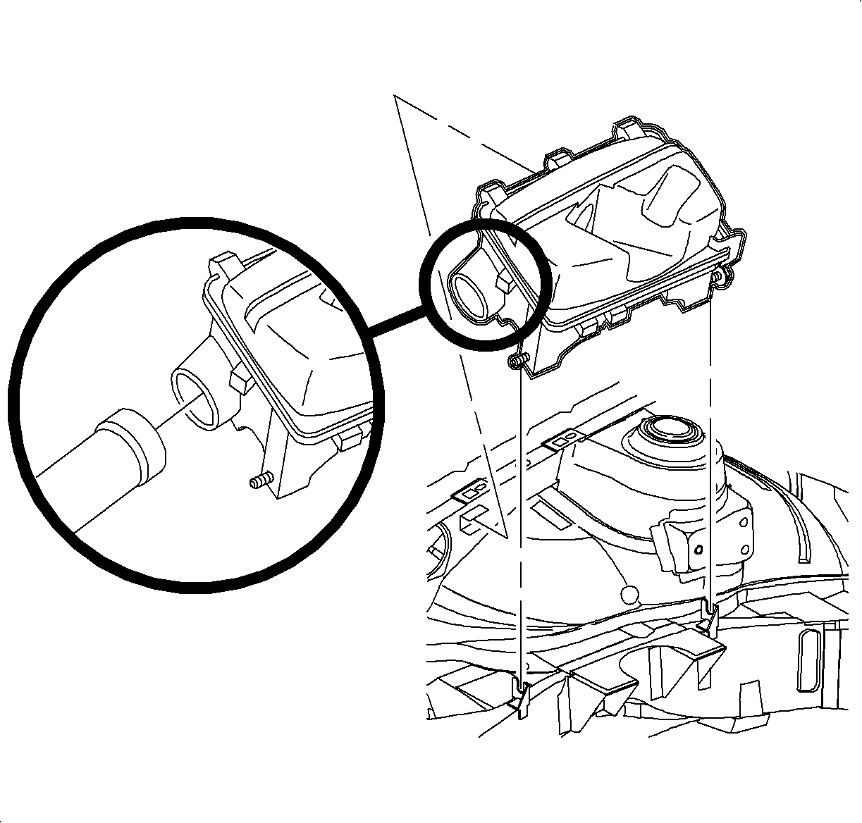
- Remove air cleaner assembly.
- Raise and support vehicle.
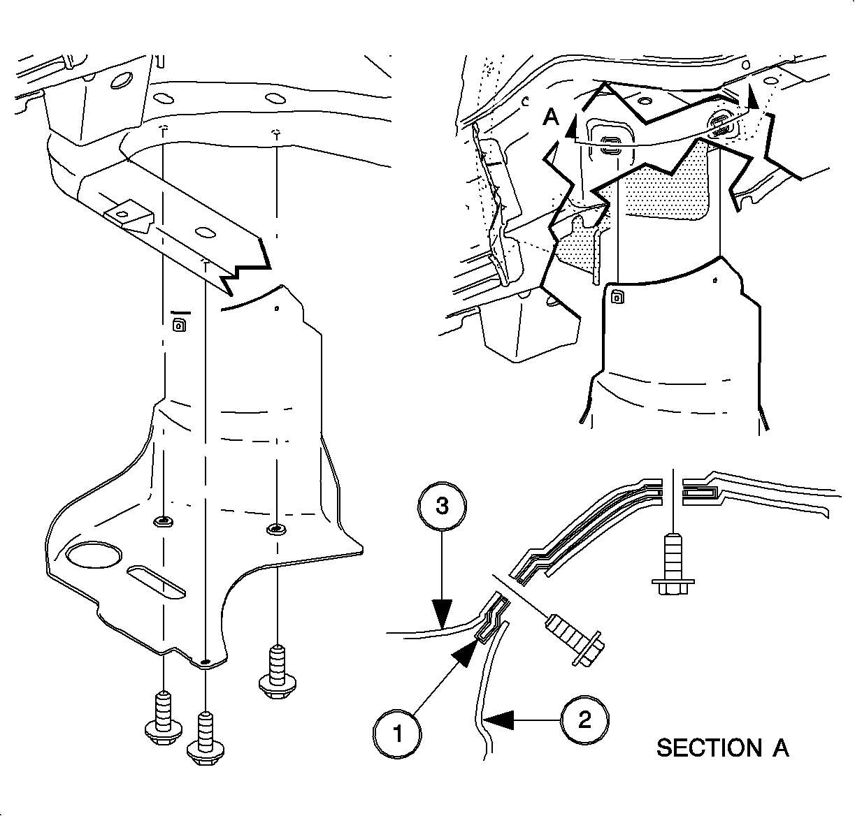
- Remove splash shield bolts.
- Remove splash shield.
- Lower vehicle.
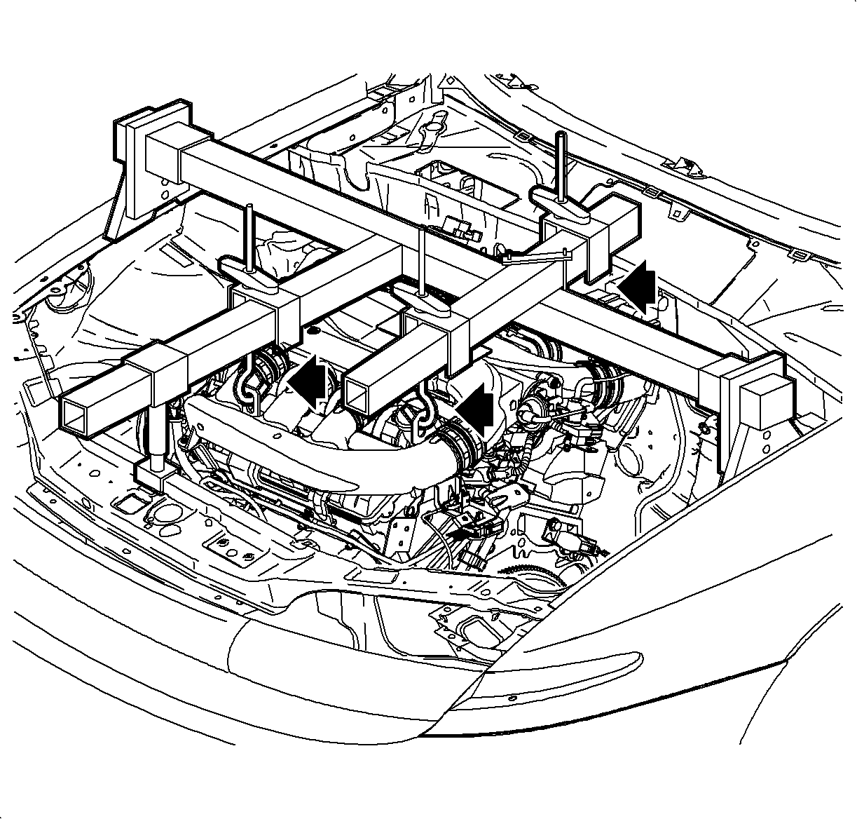
- Install engine support fixture and adapters, Engine Support Fixture (3 Bar) SA9105E and Engine Support Fixture Adapter J43405.
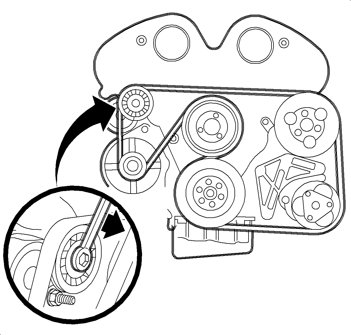
- Remove accessory drive belt using a 15 mm wrench to compress tensioner.
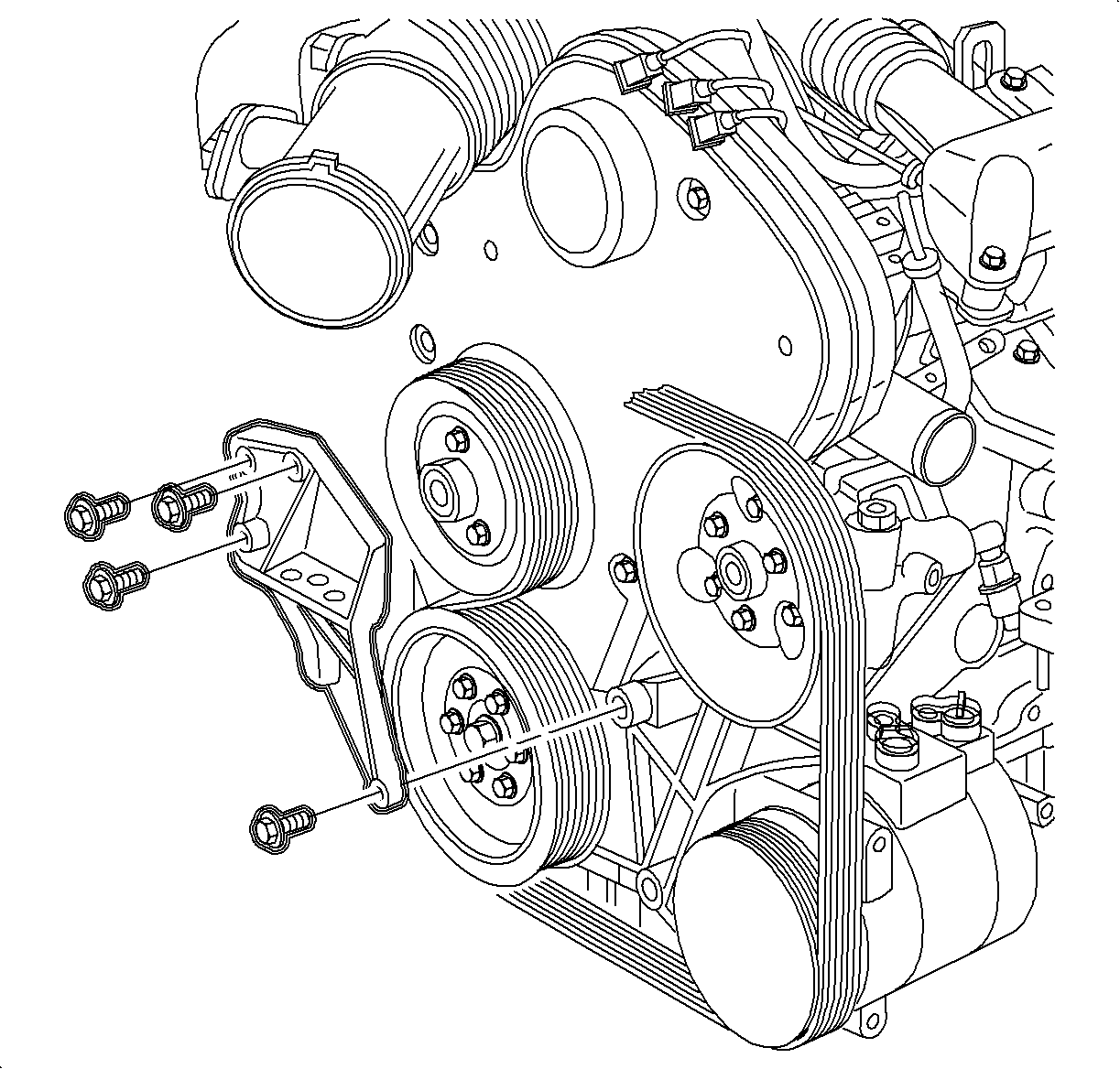
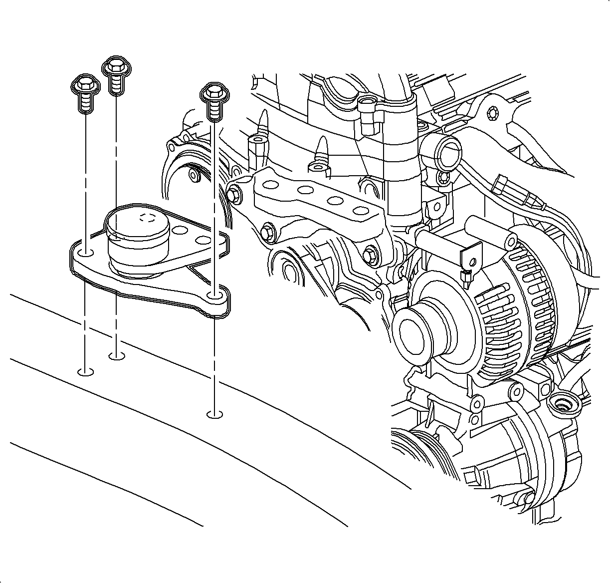
- Remove engine mount bracket bolts.
- Remove engine mount bracket from engine.
- Remove right engine mount to body mount.
- Loosen water pump and power steering pulley bolts. Do not remove fastening bolts at this time.
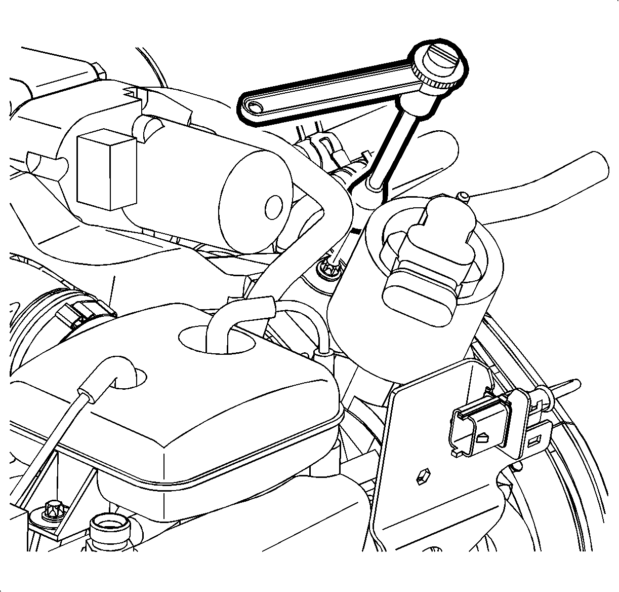
- Disconnect A/C pressure sensor electrical connector.
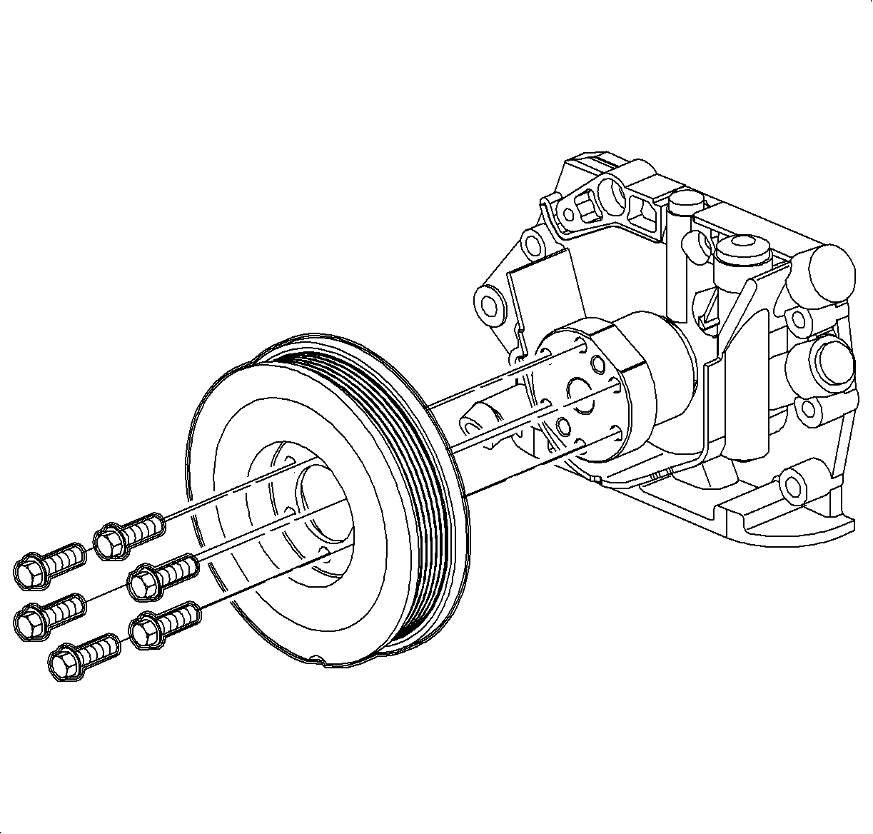
- Remove water pump pulley bolts
- Remove water pump pulley.
- Remove power steering pump pulley bolts.
- Remove power steering pump pulley.
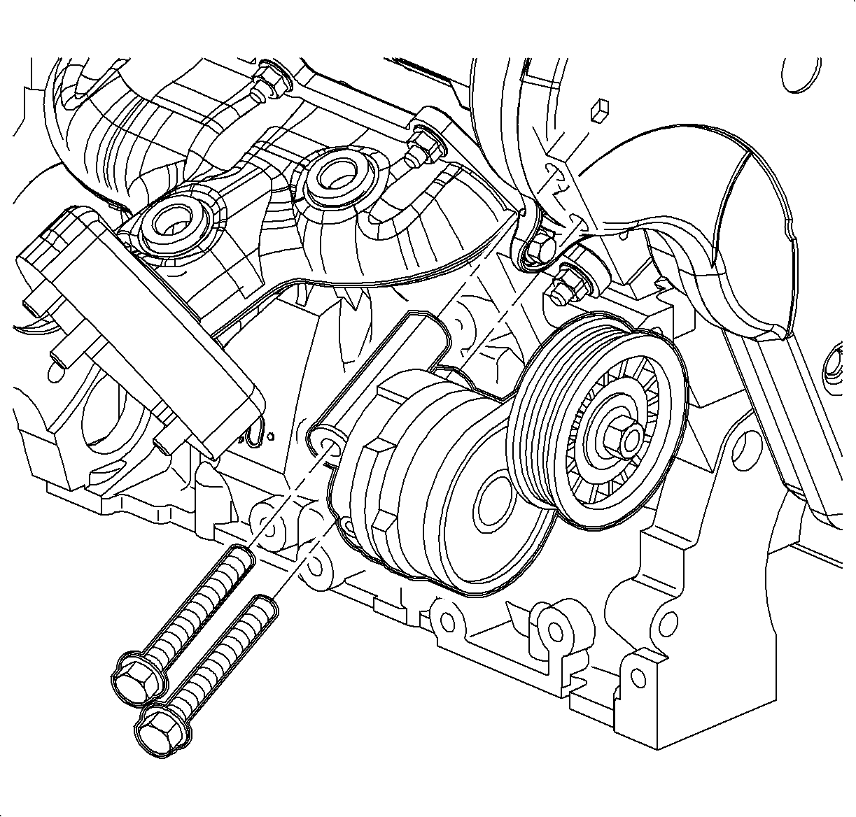
- Remove accessory drive belt tensioner bolts.
- Remove accessory drive belt tensioner.
- Remove crankshaft balancer.
- Remove fuel lines from both clips on top of engine.
- Remove purge line from clip on back of strut tower.
- Remove throttle body wire harness from bracket on rear timing belt cover.
- Remove EGR pipe heat shield bolt.
- Remove wiring harness channel from cover and secure away from front of engine.
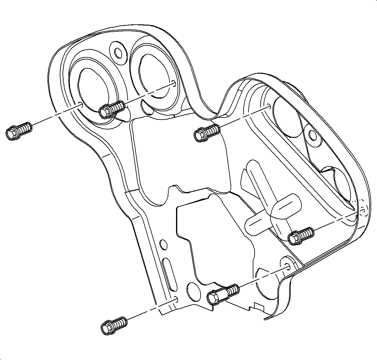
- Remove front timing belt cover bolts.
- Remove front timing belt cover.
- Inspect sealing strip on outer edge of front timing belt cover for cracks and/or tears. Replace if necessary.
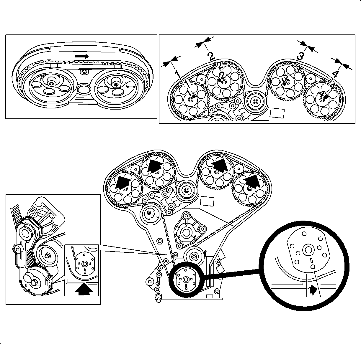
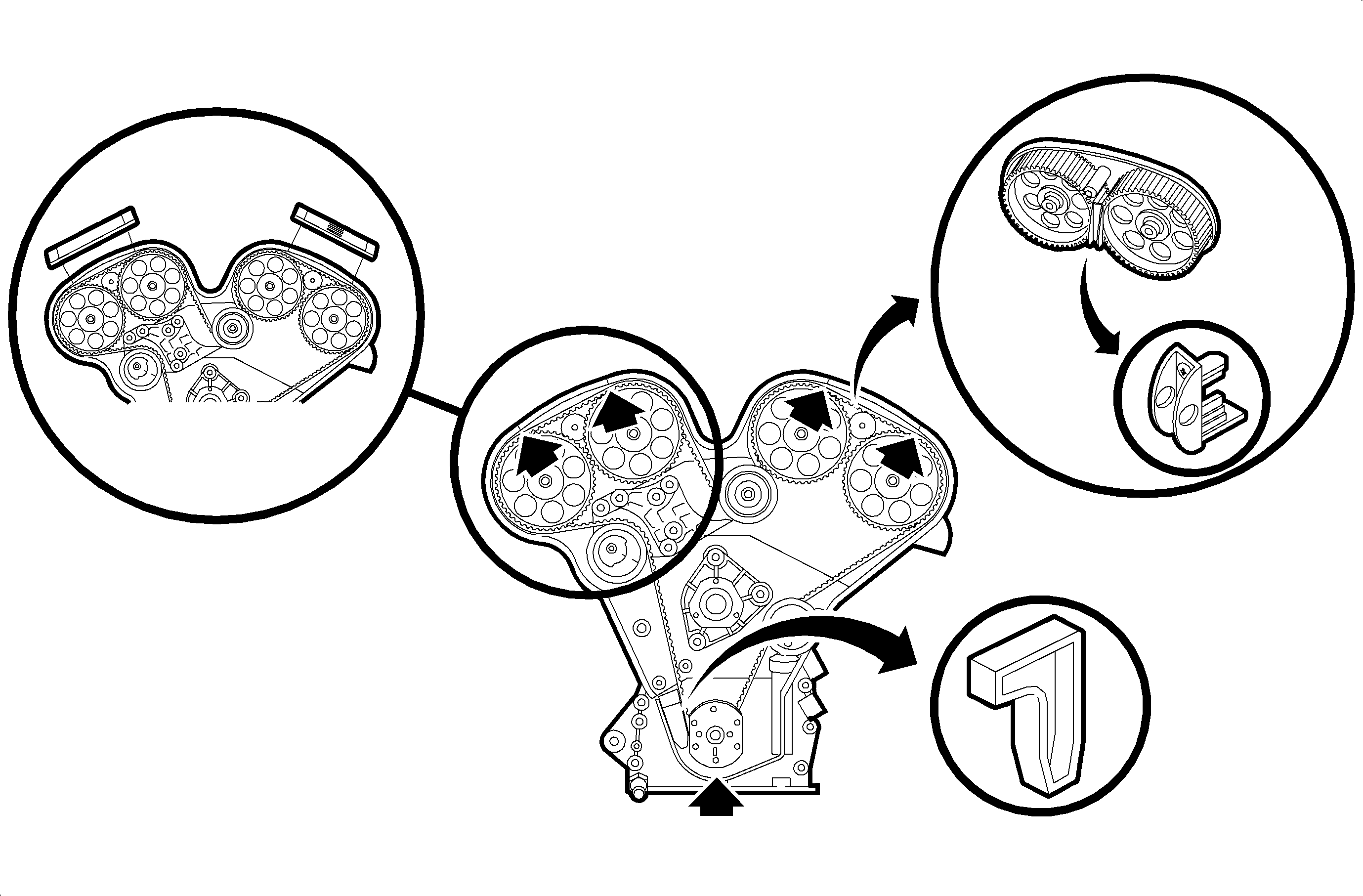
- Rotate crankshaft using Crank Hub Torx Socket J 42098 until #1 cylinder is at 60° Before Top Dead Center (BTDC).
- Install crankshaft locking tool, Timing Belt Alignment Kit J 42069-10.
- Rotate crankshaft in the engine rotational direction (clockwise) using crank hub Torx socket J42098 until #1 cylinder is at TDC and tighten lever arm to the water pump pulley flange.
- Install 1-2 and 3-4 camshaft locks, timing belt alignment kit J 42069-1 and J 42069-2.
- Remove upper and lower idler pulleys.
- Loosen timing belt tensioner.
- Remove crankshaft locking tool.
- Remove timing belt.
- As a precaution, rotate crankshaft counterclockwise to 60 degrees BTDC position to prevent valve/piston contact.
- Remove camshaft gears. Use Timing Belt Alignment Kit J 42069-1 and J 42069-2 camshaft locks to lock gears when initially loosening camshaft gear bolts.
- Remove timing belt tensioner bracket bolts.
- Remove timing belt tensioner bracket.
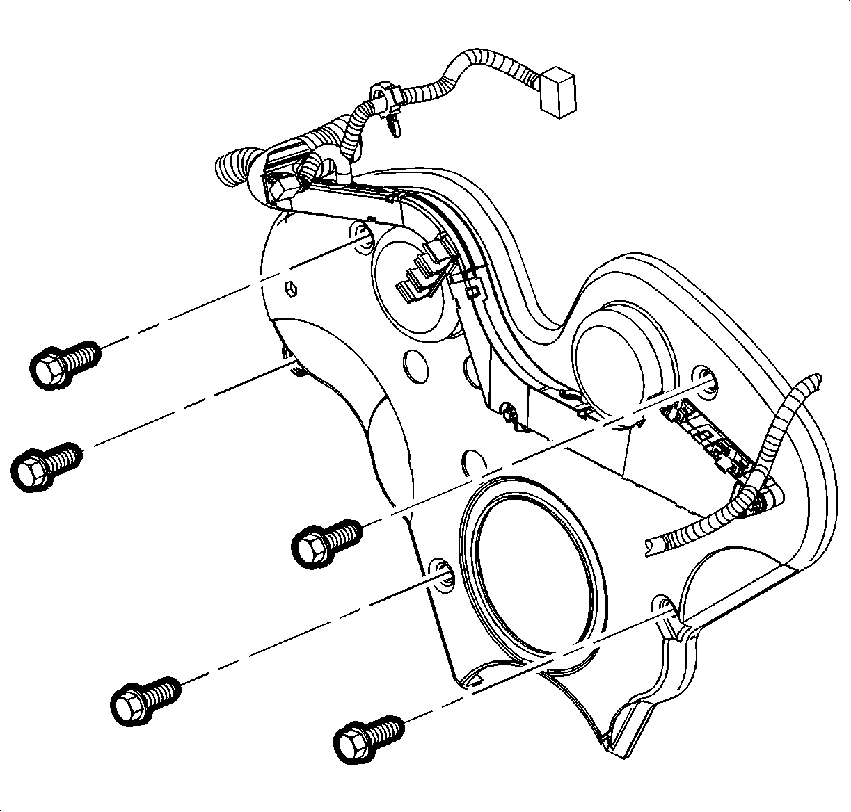
- Remove rear timing belt cover bolts.
- Remove rear timing belt threaded pin.
- Remove knock sensor 1 pigtail from the 3 clips on side of rear timing belt cover.
- Remove rear timing belt cover.
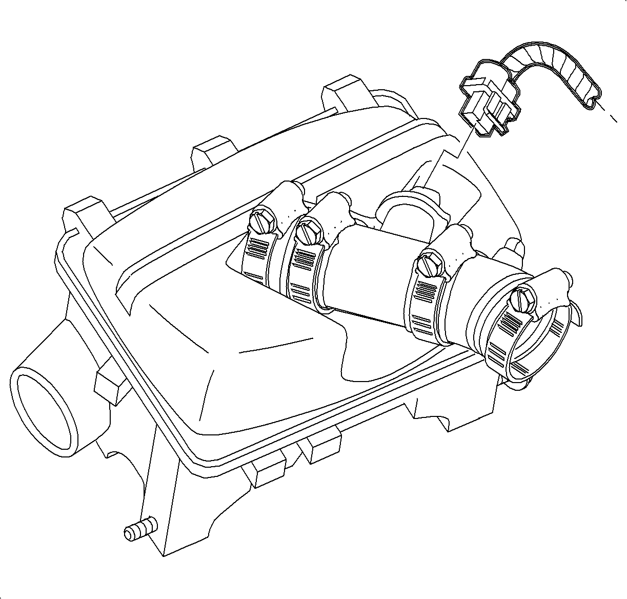
| 2.1. | Disconnect mass air flow (MAF) electrical connector. |
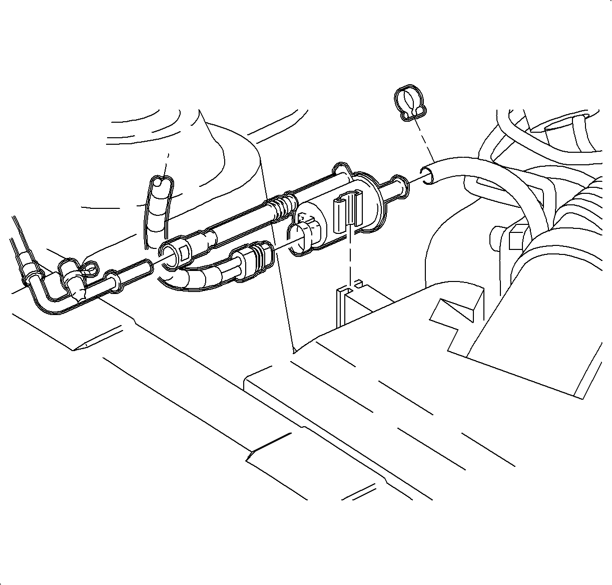
| 2.2. | Unsnap EVAP purge valve assembly and secure out of the way of air cleaner assembly. |
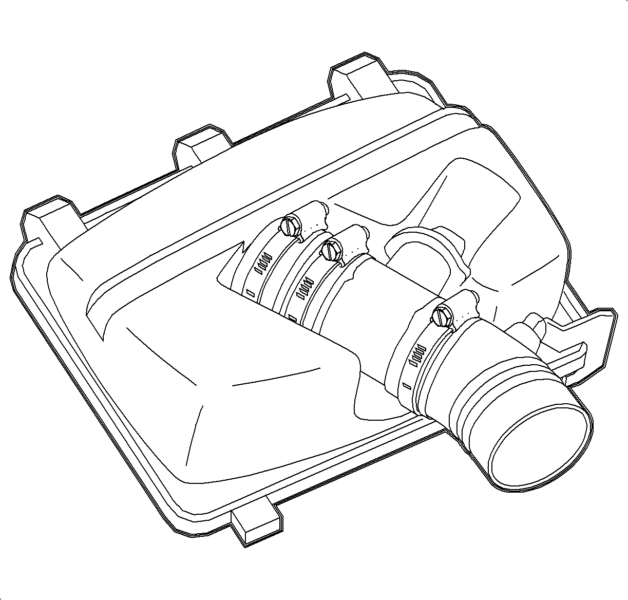
| 2.3. | Remove air cleaner lid: |
| • | Loosen hose clamp at throttle body. |
| • | Slide off flexible MAF hose to throttle body hose. |
| • | Unclamp air cleaner lid. |
| • | Remove air cleaner lid, MAF sensor, and hose as an assembly. |
| 2.4. | Remove air cleaner from air box. |
| 2.5. | Remove air box mount bolt. |
| 2.6. | Remove air box. |
Caution: Make sure vehicle is properly supported and squarely positioned. To help avoid personal injury when a vehicle is on hoist, provide additional support for the opposite end from which components are being removed. Make sure hoist does not contact fuel or brake lines.

Important: Ensure that the alignment of crankshaft is not 360 degrees off. The alignment marks must align with the corresponding notches on the rear timing belt cover.
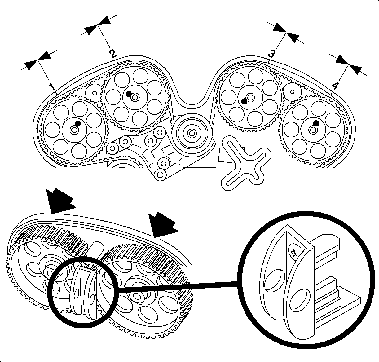
Important: Do not rotate crankshaft if camshafts are not locked in place with 1-2 and 3-4 camshaft locks, timing belt alignment kit J 42069-1 and J 42069-2.
Important: Do not rotate camshafts unless crankshaft is at 60° BTDC or valves may contact crankshaft.
Installation
- Transfer the three knock sensor 1 pigtail clips to the new rear timing belt cover.
- Transfer fuel line bracket to new rear timing belt cover.
- Install new rear timing belt cover that came in the kit.
- Install rear timing belt cover bolts.
- Coat threaded pin with Threadlocker Loctite® 242 compound or equivalent.
- Install rear timing belt threaded pin.
- Install knock sensor 1 pigtail into the three clips on rear timing belt cover.
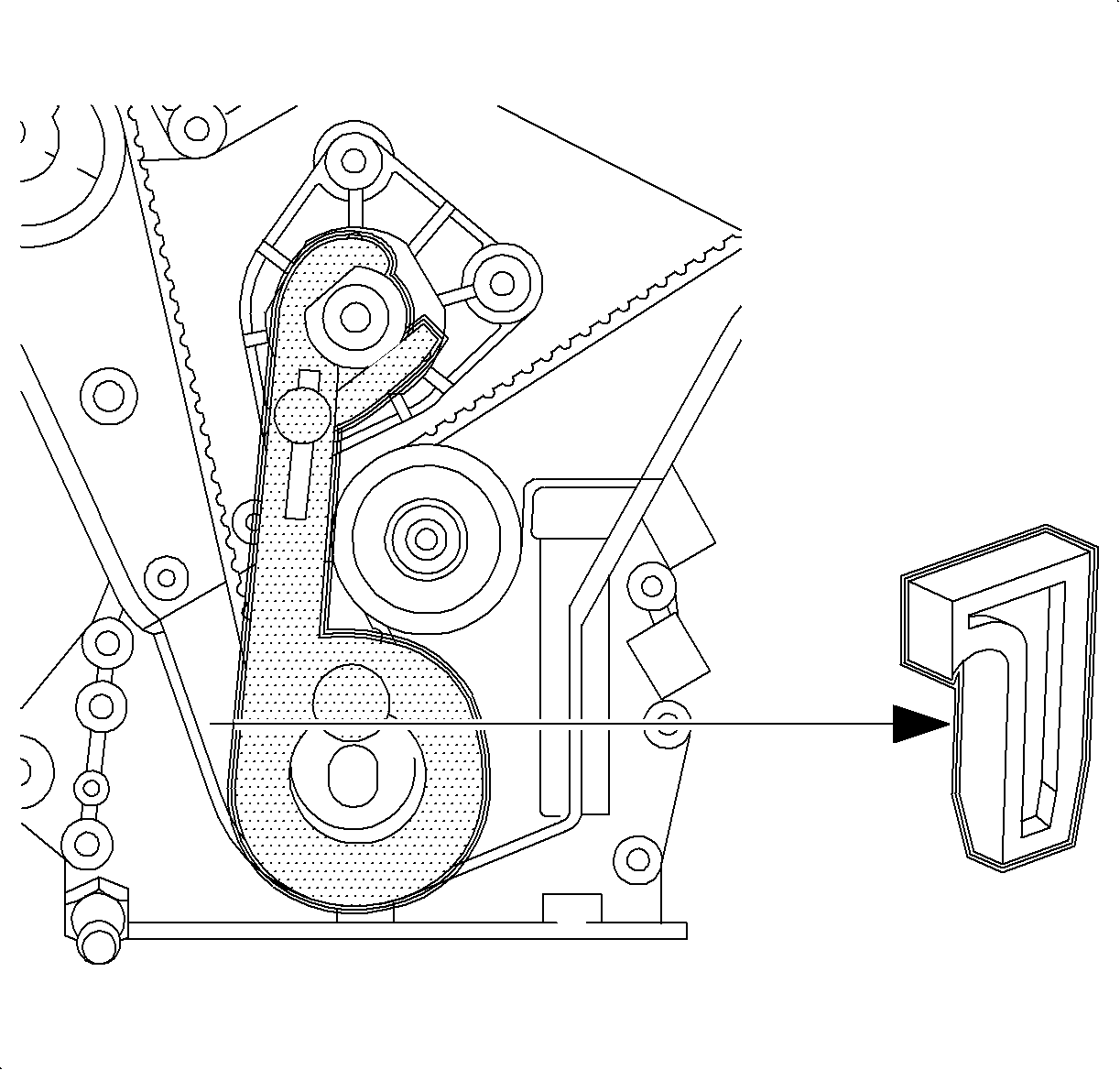
- Install new timing belt tensioner bracket with tensioner and idler that came in the kit.
- Install timing belt tensioner bracket bolts.
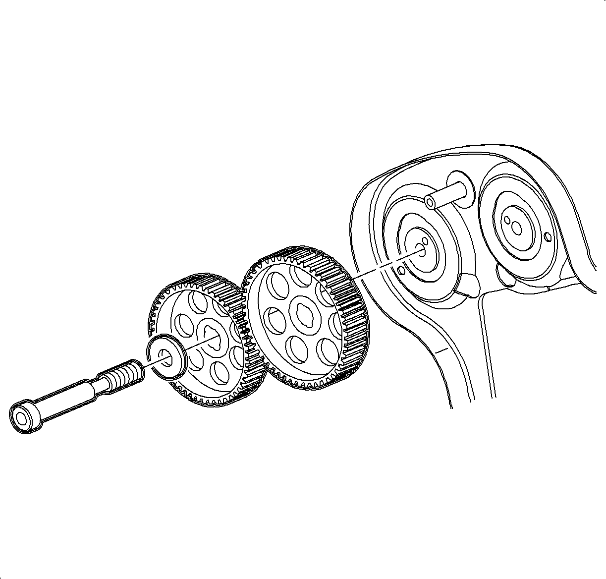
- Install camshaft gears.
- Install camshaft gear bolts.
- Mark upper and lower idler pulleys. Use a felt pen to mark the face of the idler pulleys. The mark should line up with the point furthest away from the Torx® head mounting bolt.
- Align timing marks on each camshaft sprocket with notch in rear timing belt cover.
- Reinstall crankshaft locking tool J 42069-40 and rotate crankshaft to TDC.
- Remove crankshaft locking tool J 42069-40 to ease installation of timing belt.
- Install lower idler pulley. Tighten just enough to allow the pulley to rotate with slight resistance using idler pulley wrench J42069-40.
- With upper idler pulley removed, install timing belt.
- Reinstall crankshaft locking tool J 42069-10, and tighten lever arm to the water pump pulley flange.
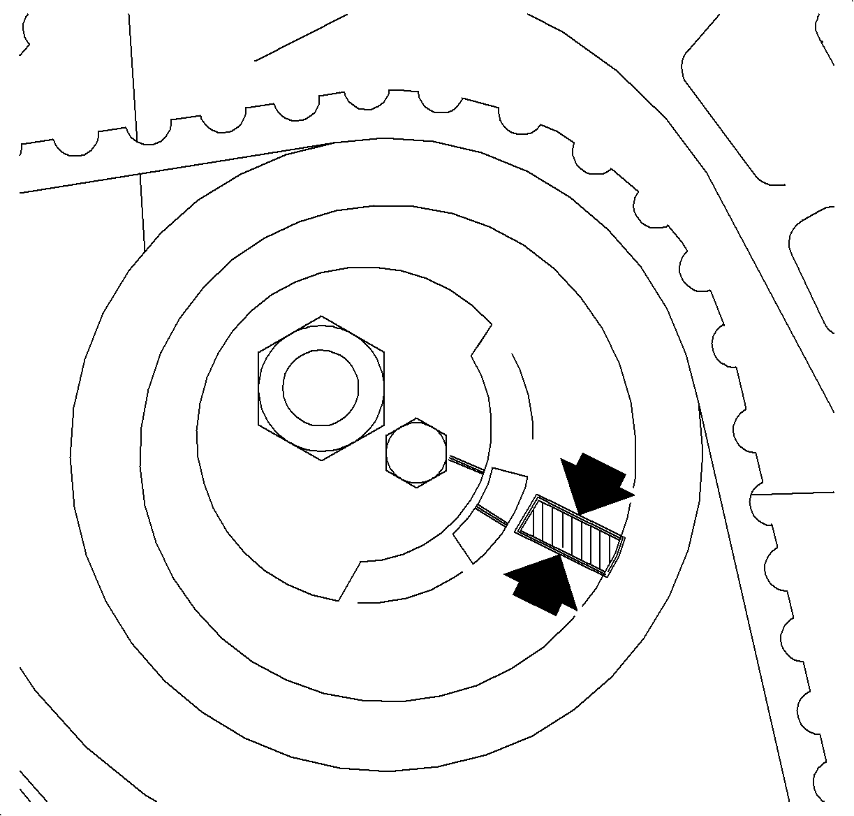
- Adjust timing belt tensioner so that the center alignment mark is about 3 mm (1/8 in.) above alignment mark on spring loaded idler.
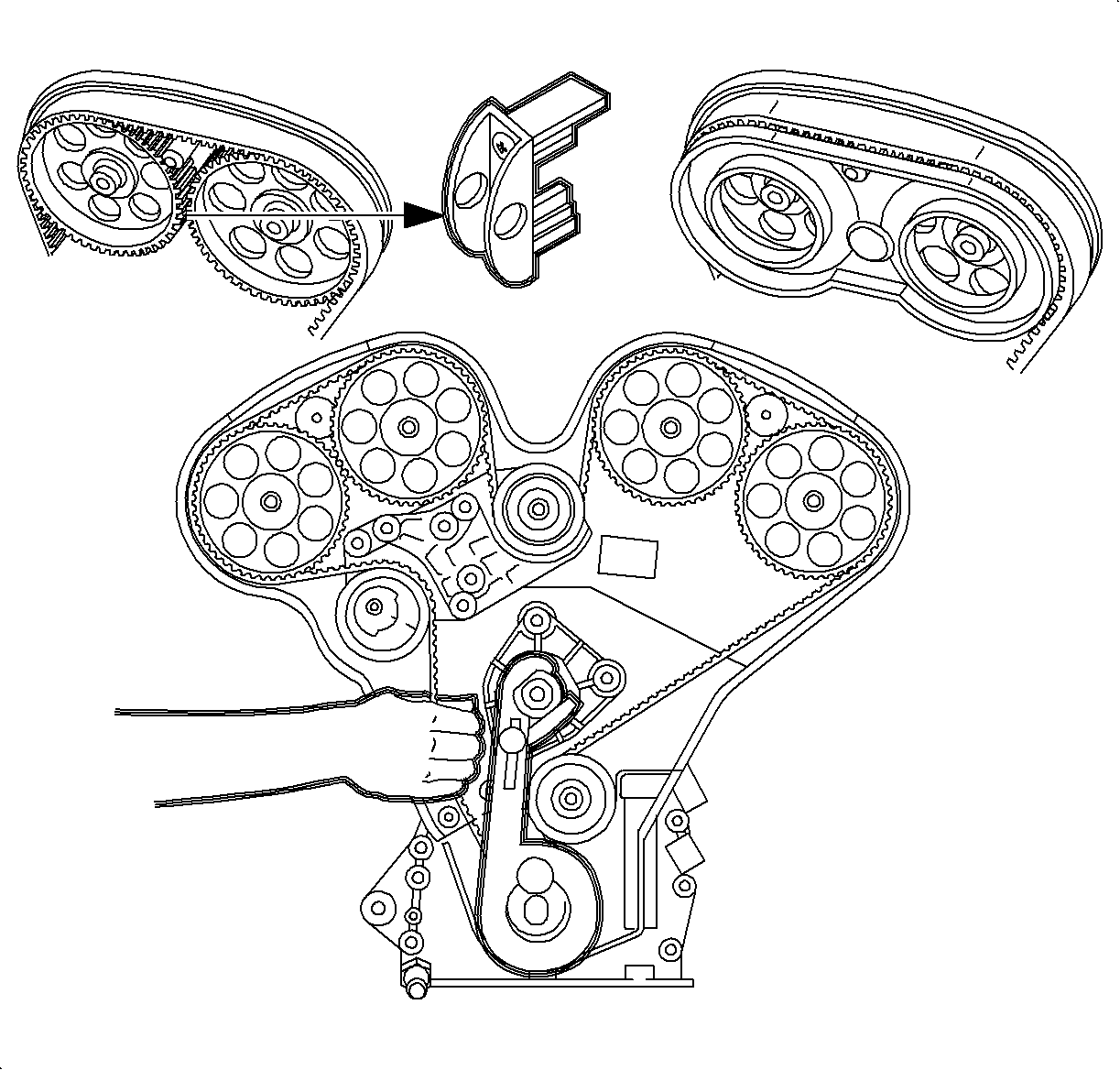
- Remove plastic wedge J 42069-30 from crankshaft sprocket.
- Adjust upper idler pulley to approximately the 10 o'clock position. This will get the #1 and #2 timing marks close to their settings. Tighten until snug, but do not torque at this time.
- Adjust lower idler pulley to approximately the 11 o'clock position. This will get the #3 and #4 timing marks close to their settings. Tighten until snug, but do not torque at this time.
- Remove 1-2 and 3-4 camshaft locks, timing belt alignment kit J 42069-1 and J 42069-2.
- Install J 42069-20 checking gauge to cams 3 and 4.
- Pull belt between the timing belt tensioner and crankshaft sprocket to take up slack between cams 3-4 and the lower idler pulley.
- Remove crankshaft locking tool J 42069-10.
- Rotate crankshaft 1 3/4 turns clockwise. Install J 42069-10 and then stop at TDC.
- Tighten lever arm to the water pump pulley flange.
- Adjust lower idler pulley by rotating counterclockwise until the 3-4 timing marks on the sprockets are lined up with marks on J 42069-20 checking gauge.
- Tighten idler pulley, using J 42069-40 alignment tool to hold pulley while tightening fastener.
- Remove J 42069-10 crankshaft locking tool.
- Rotate crankshaft 1 3/4 turns clockwise. Install J 42069-10 and then stop at TDC.
- Tighten lever arm to the water pump pulley flange.
- Inspect 3-4 timing marks for alignment and realign if necessary.
- Remove J 42069-20 checking gauge from 3-4 camshaft sprockets and install on 1-2 camshaft sprockets.
- Install J 42069-2 green camshaft locking tool onto 3-4 camshafts.
- Adjust upper idler pulley by rotating counterclockwise until the 1-2 timing marks on the sprockets are lined up with marks on J 42069-20 checking gauge.
- Tighten idler pulley, using J 42069-40 alignment tool to hold pulley while tightening fastener.
- Remove J 42069-2 green camshaft locking tool from 3-4 camshafts and J 42069-10 crankshaft locking tool from crankshaft.
- Rotate crankshaft 1 3/4 turns clockwise. Install J 42069-10 and then stop at TDC.
- Tighten lever arm to the water pump pulley flange.
- Recheck both pairs of camshaft timing marks using J 42069-20 checking gauge.
- Tighten both idler pulleys using J 42069-40 alignment tool to hold pulleys while torquing fasteners.
- Adjust timing belt tensioner so that the center alignment mark is about 3 mm above alignment mark on spring loaded idler.
- Tighten timing belt tensioner.
- Verify timing marks are still aligned.
- Remove J 42069-10 crankshaft locking tool and J 42069-20 checking gauge.
- Install front timing belt cover.
- Install front timing belt cover bolts.
- Install crankshaft balancer.
- Install accessory drive belt tensioner.
- Install accessory drive belt tensioner bolts.
- Install power steering pump pulley.
- Install power steering pump pulley bolts.
- Snug power steering pump pulley bolts. The bolts will be tightened to proper specification when serpentine drive belt is installed.
- Install water pump pulley.
- Install water pump pulley bolts. Snug the water pump pulley bolts. The bolts will be tightened to proper specification when the accessory drive belt is installed.
- Install wiring harness channel to front timing belt cover.
- Install accessory drive belt.
- Tighten water pump pulley and power steering pulley bolts.
- Install throttle body wire harness rosebud into fuel line bracket.
- Install EGR pipe heat shield bolt.
- Install fuel lines into both clips on top of engine.
- Install engine mount bracket and tighten bolts.
- Install engine mount to frame rail and engine mount bracket.
- Remove engine support fixture.
- Raise vehicle.
- Install splash shield.
- Install splash shield bolts. Tighten splash shield bolts until fully seated. Do not strip bolts
- Lower vehicle.
- Reconnect A/C pressure sensor electrical connector.
- Install air cleaner assembly.
- Install EVAP purge line into clip on rear of strut tower.
- Reconnect negative battery cable.
Tighten
Tighten the fuel line bracket bolt to 8 N·m (71 lb in).

Tighten
Tighten the rear timing belt cover bolt to 8 N·m (71 lb in).
Tighten
Tighten the timing belt cover threaded pin to 10 N·m (89 lb in).

Tighten
Tighten the rear timing belt cover thread pin to 8 N·m (71 lb in).
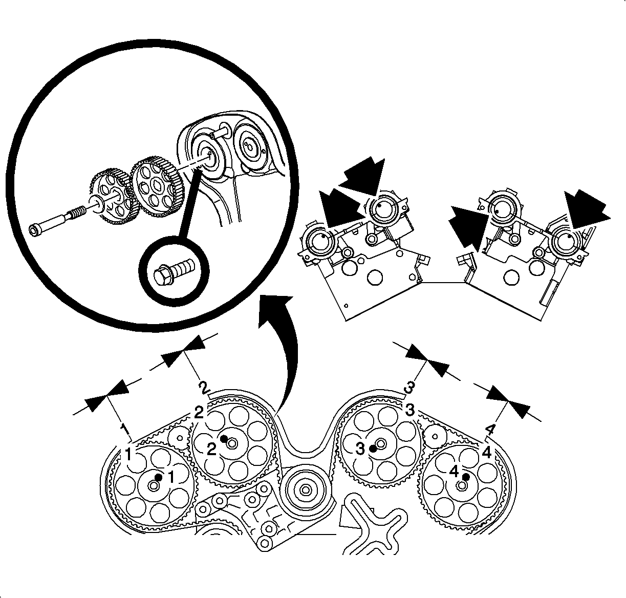
Important: Install alignment pin in correct numbered, alignment slot on each camshaft gear.
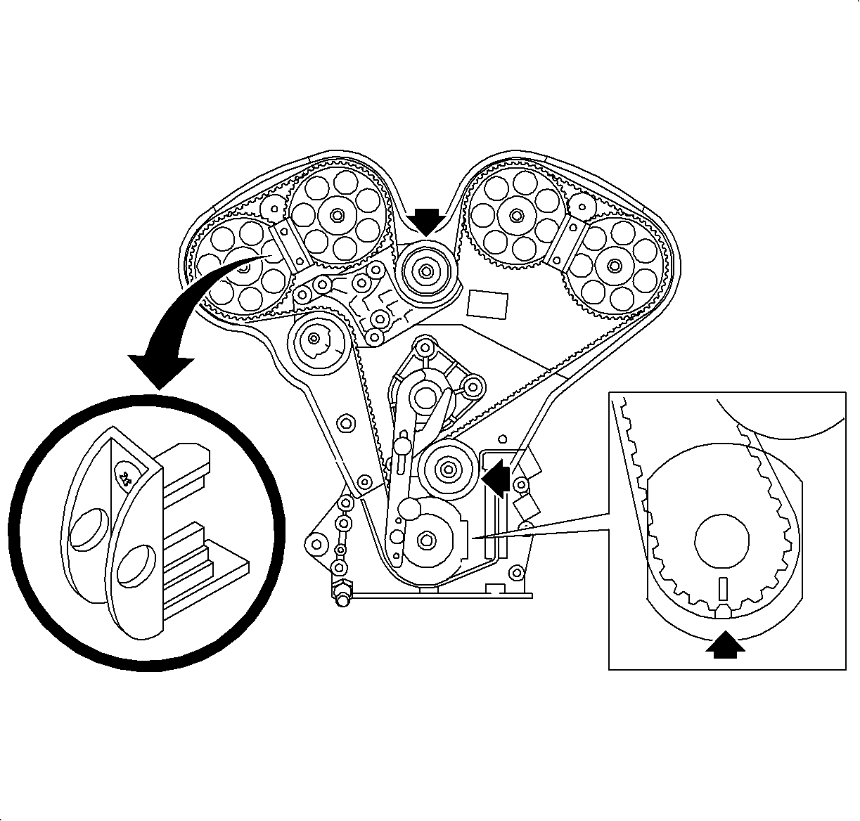
Important: Use new camshaft gear bolts. The required tightening method will stretch to its yield point, therefore, the bolt is not reusable.
| • | Use Timing Belt Alignment Kit J 42069-1 and J 42069-2 to hold camshaft gears and camshaft in place while tightening camshaft gear bolts. |
| • | Tighten camshaft gear bolt. |
Tighten
Tighten the camshaft gear bolt to 50 N·m (37 lb ft)
+ 60° + 15°.
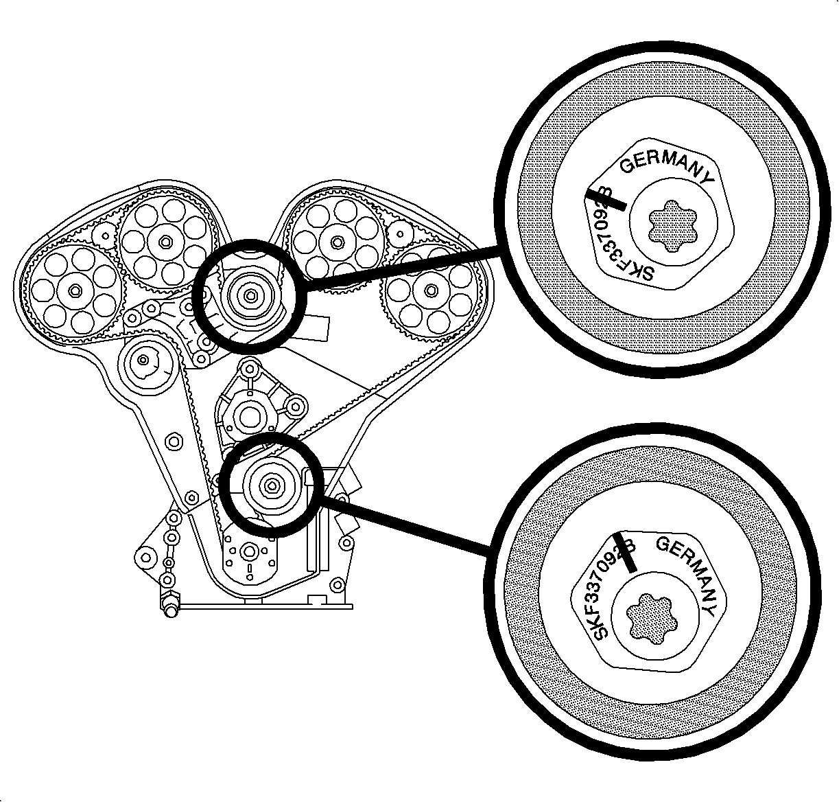
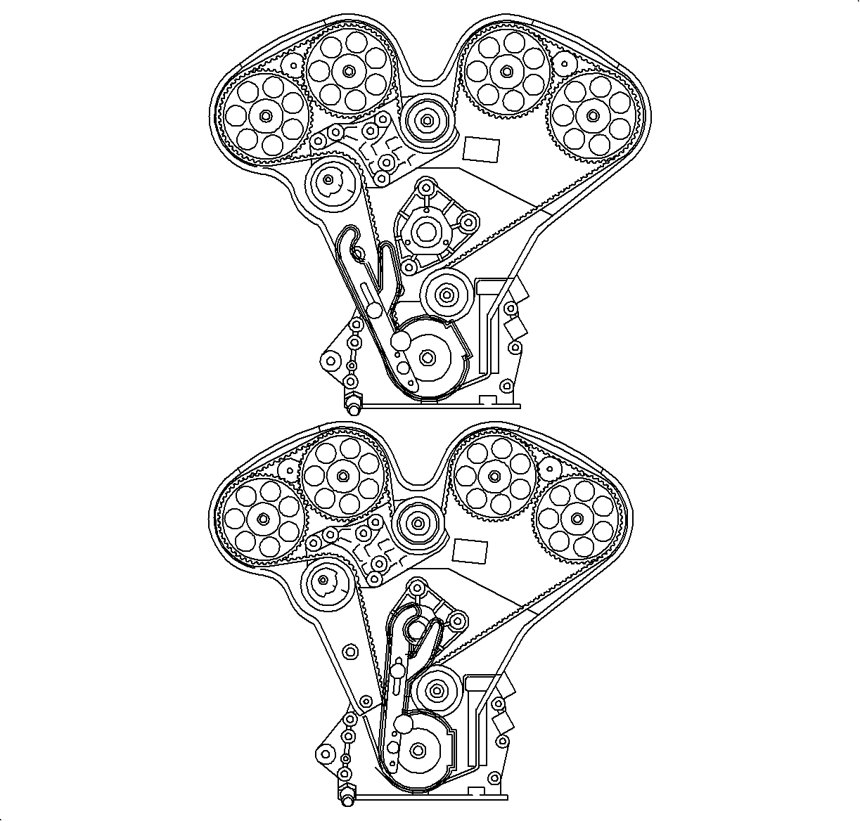
Notice: The upper idler pulley (cams 1 and 2) and lower idler puller (cams 3 and 4) use different bolts and spacers of different thicknesses. The upper idler pulley uses a narrow 5 mm (0.20 in.) thick spacer and a black bolt. The lower idler pulley uses an 11 mm (0.40 in.) thick spacer and a silver bolt.
Important: The idler pulleys provide adjustment by rotating on an eccentric circle around the attachment bolt.
| 17.1. | Align marks on timing belt with corresponding marks on #3 and #4 camshaft sprockets. |
| 17.2. | Install timing belt around lower idler pulley |
| 17.3. | Install timing belt around crankshaft sprocket. Ensure that mark on timing belt is aligned with mark on crankshaft sprocket face. |
| 17.4. | Lock timing belt onto crankshaft sprocket using plastic wedge J 42069-30. |
| 17.5. | Install timing belt around timing belt tensioner and align marks on timing belt with corresponding marks on #1 and #2 camshaft sprockets. |
| 17.6. | Install upper idler pulley. Tighten just enough to allow the pulley to rotate with slight resistance using idler pulley wrench J 42069-40. |
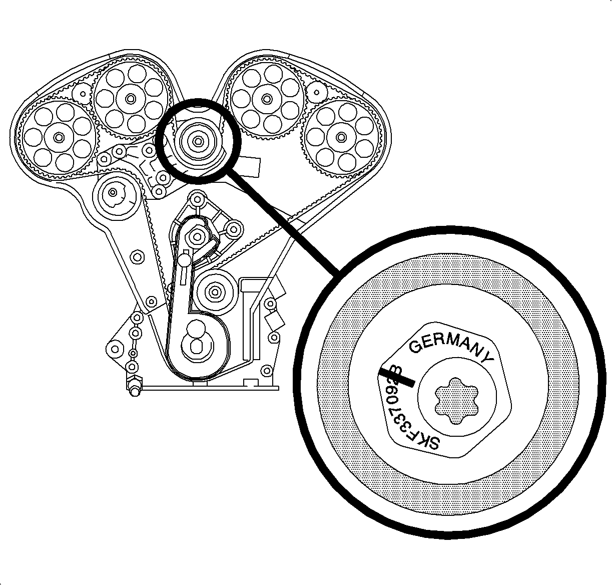
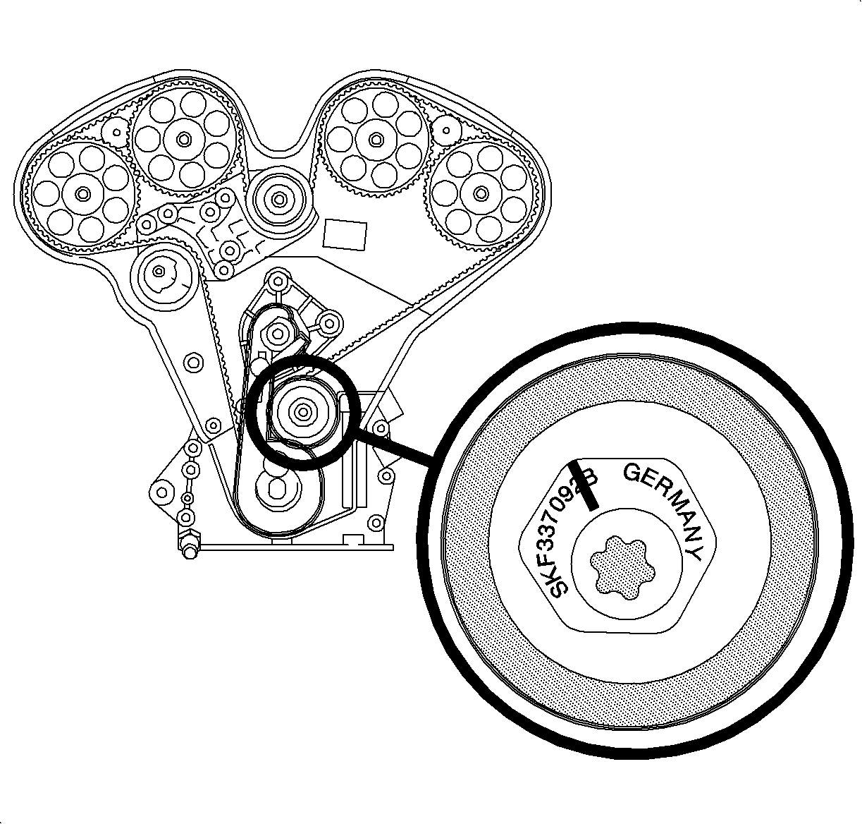
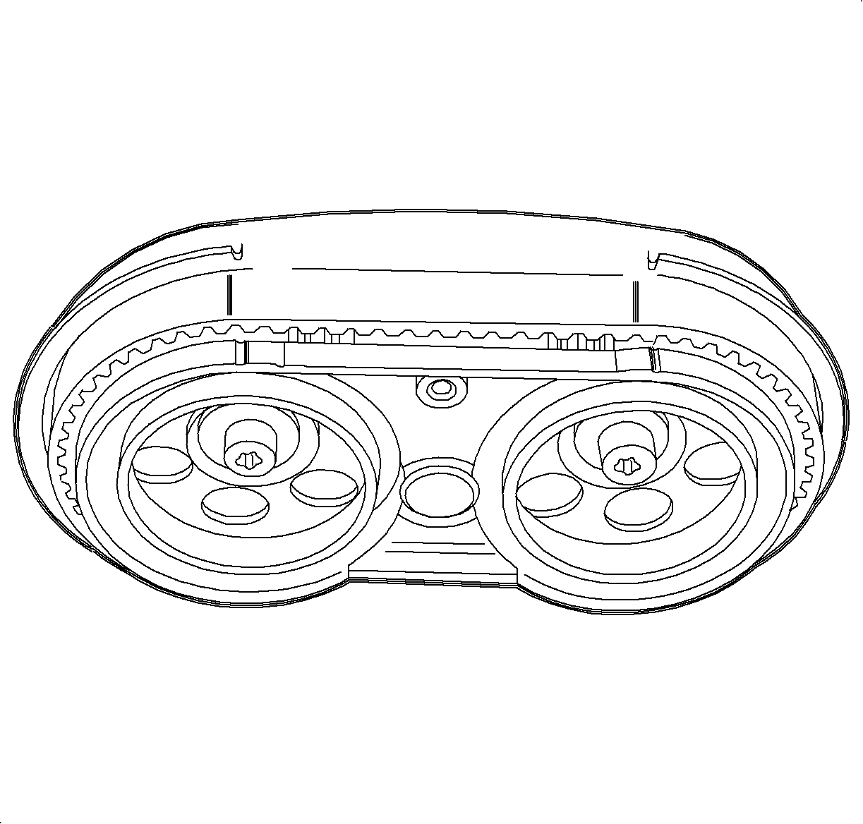
Important: Ensure that the 3-4 cam timing marks are about 1 mm (approximately the width of the timing marks on the sprockets) on the retard side. If they are not, turn lower idler clockwise to allow retard of the 3-4 cams and repeat previous step.
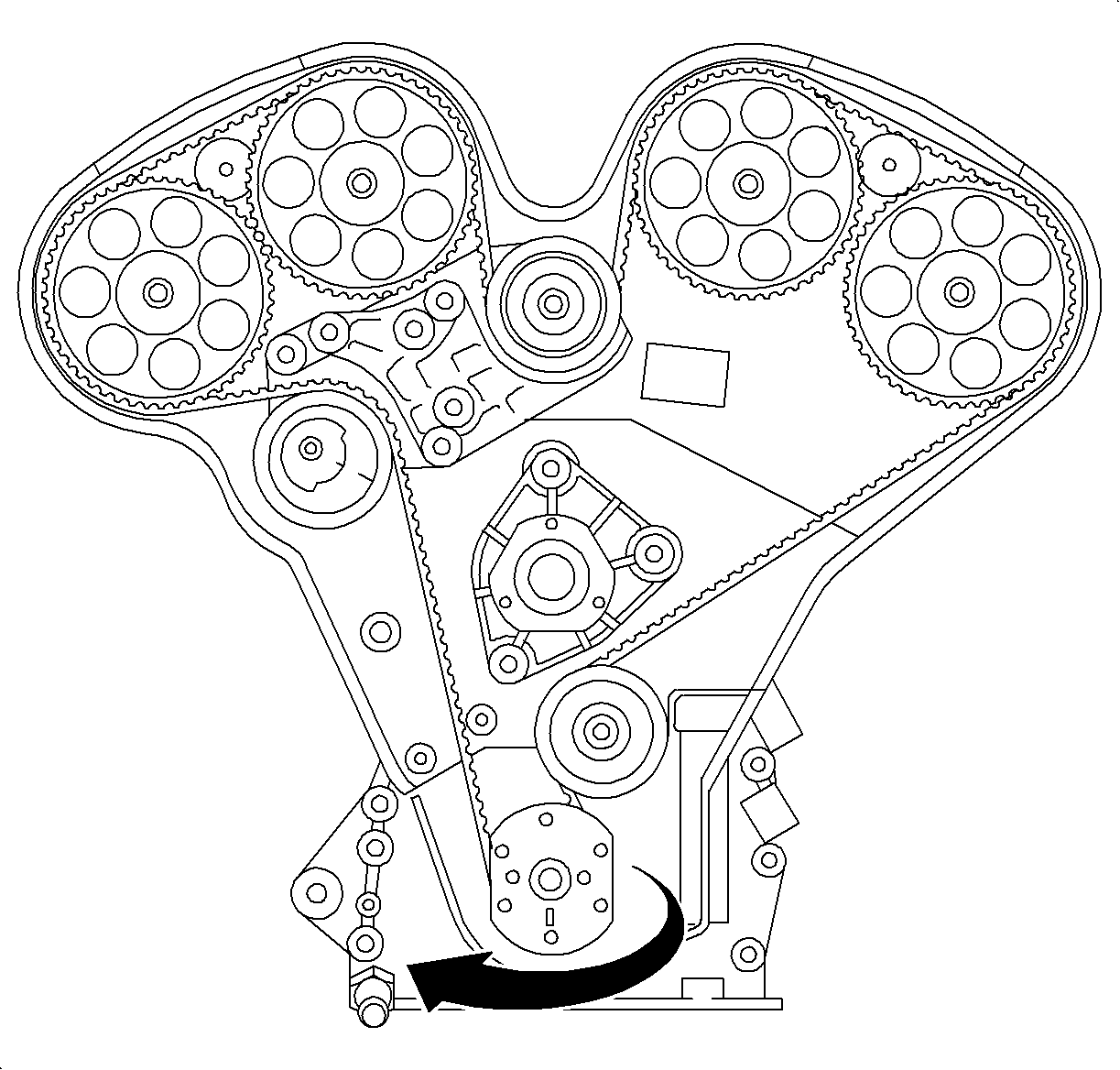
Important: If TDC is passed, do not rotate crankshaft counterclockwise. This will not allow proper slack to be taken up between timing belt tensioner and crankshaft sprocket. To correct, rotate crankshaft additional two turns.

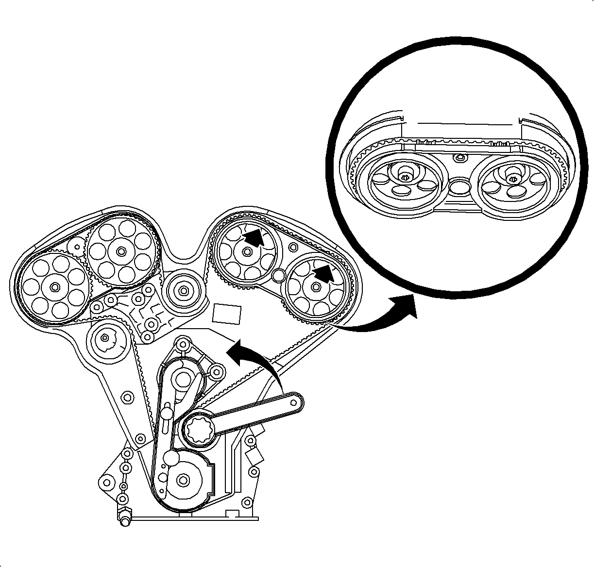
Important: Timing marks on timing belt are used for initial installation only.
Tighten
Tighten the idler pulley fastener to 20 N·m (15 lb ft).

Important: If TDC is passed, do not rotate crankshaft counterclockwise this will not allow proper slack to be taken up between timing belt tensioner and crankshaft sprocket. To correct, rotate crankshaft additional two turns.

Important: Timing marks on timing belt are used for initial installation only.
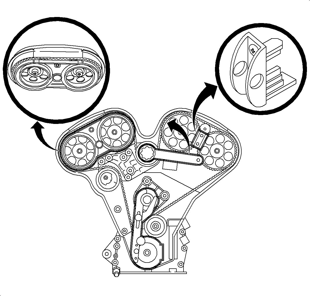
Tighten
Tighten the idler pulley fastener to 20 N·m (15 lb ft).

Important: If TDC is passed, do not rotate crankshaft counterclockwise. This will not allow proper slack to be taken up between timing belt tensioner and crankshaft sprocket. To correct, rotate crankshaft additional two turns.
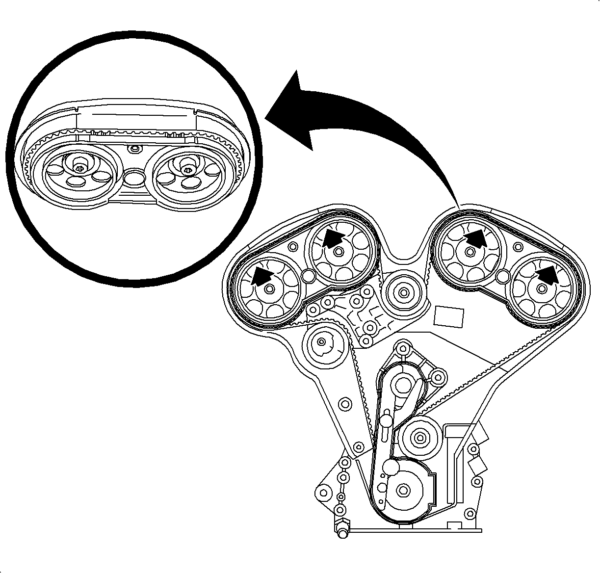
Important: If timing marks are off, repeat procedures to readjust. Removal of timing belt is not necessary.
Tighten
Tighten the idler pulley fastener to 20 N·m (15 lb ft).

Tighten
Tighten the timing belt tensioner fastening nut to 20 N·m (15 lb ft).

Tighten
Tighten the front timing belt cover bolt to 8 N·m (71 lb in).

Tighten
Tighten the crankshaft balancer bolt to 20 N·m (15 lb ft).

Tighten
Tighten the belt tensioner bolt to 40 N·m (30 lb ft).
Tighten
Tighten the wire harness channel to 6 N·m (53 lb in).
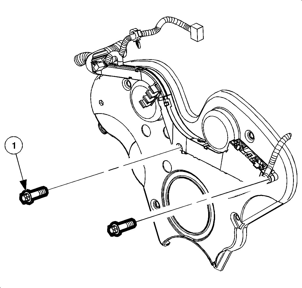
Important: Prior to installing bolts, slide washer from kit (P/N 11011619) onto bolt (1) as shown in the illustration.

Tighten
Tighten the water pump pulley bolt to 8 N·m (71 lb in).
Tighten
Tighten the power steering pulley bolt to 20 N·m (15 lb ft).
Tighten
Tighten the EGR pipe heat shield bolt to 8 N·m (71 lb in).

Tighten
Tighten the engine mount bracket bolts to 55 N·m (41 lb ft).
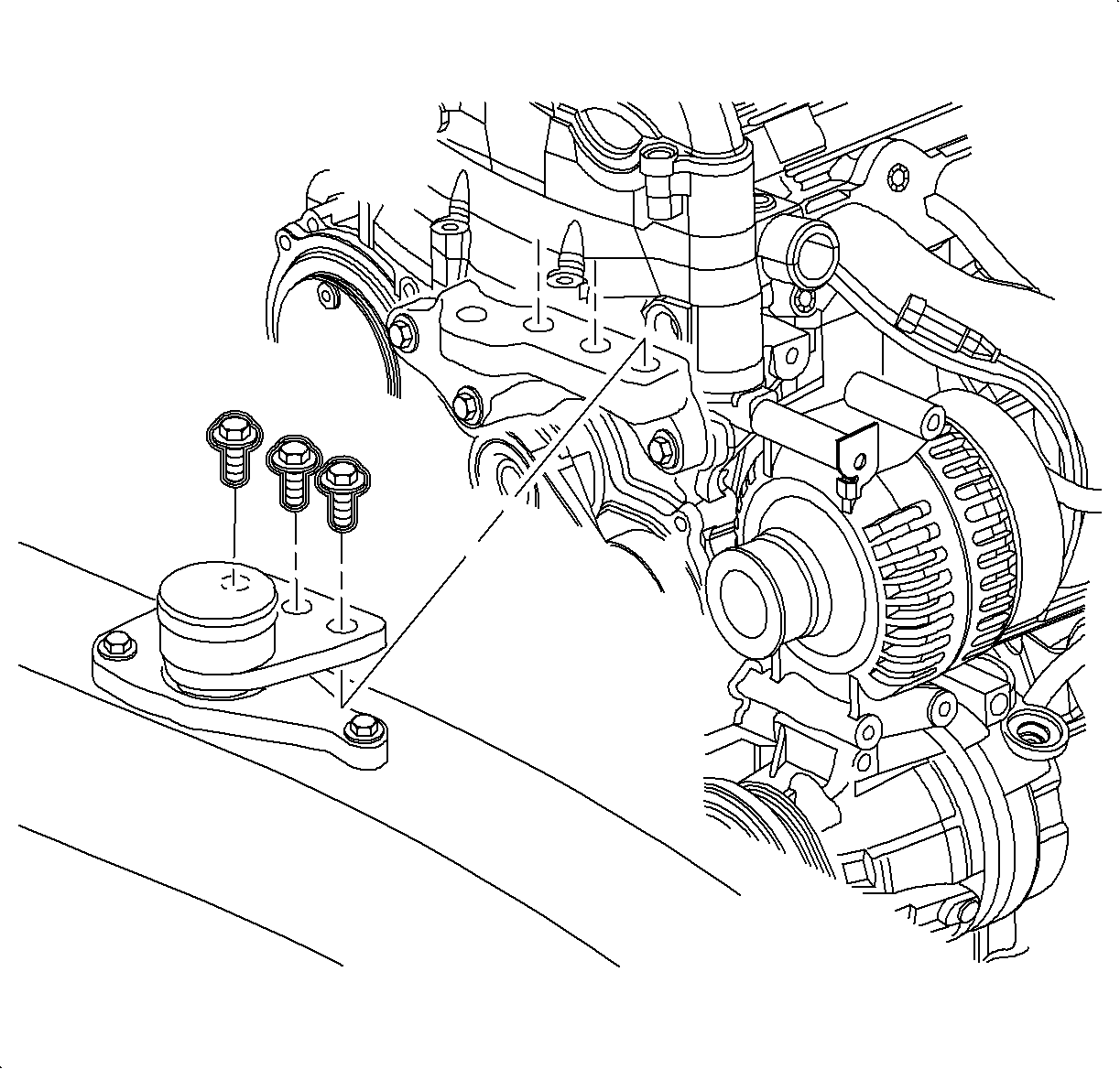
Tighten
Tighten the engine mount-to-bracket bolt to 55 N·m (41 lb ft).
Caution: Make sure vehicle is properly supported and squarely positioned. To help avoid personal injury when a vehicle is on hoist, provide additional support for the opposite end from which components are being removed. Make sure hoist does not contact fuel or brake lines.

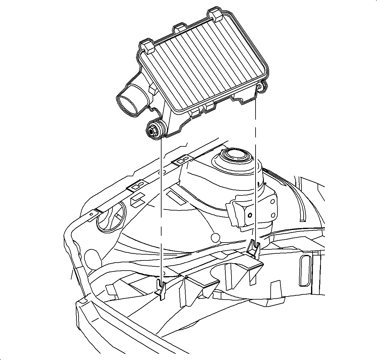
| 72.1. | Install air box. Ensure that lower pin engages into rubber mount grommet and that lower duct fits into resonator outlet. |
| 72.2. | Install air box mount bolt. |
Tighten
Tighten the air box mount bolt to 6 N·m (53 lb in).
| 72.3. | Install air cleaner. |

| 72.4. | Install air cleaner lid. Ensure that the lid hinge is fully engaged in air box slots or the lid may not properly seal. |
| - | Install air cleaner lid, MAF sensor, and hose as an assembly. |
| - | Clamp air cleaner lid. |
| - | Slide flexible MAF hose and hose clamp on throttle body. |
| - | Tighten hose clamp. |

| 72.5. | Install EVAP purge valve assembly. |

| 72.6. | Connect MAF electrical connection. |
Tighten
Tighten the battery terminal bolts to 17 N·m (13 lb ft).
Parts Requirements
Part Number | Description | Qty |
|---|---|---|
09198745 | Kit, Timing Belt | -- |
90466737 | Bolt/Screw - CM/SHF Spkt | 2 |
90573287 | Bolt/Screw - CM/SHF Spkt | 2 |
Claim Information
To receive credit for this repair during the warranty coverage period, submit a claim through the Saturn Dealer System for J0809 (Cover, Camshaft Drive Rear - Replace) If another procedure is performed, refer to the appropriate Electronic Labor Time Guide for the correct Labor Operation Code and Time.
