Circuit Description
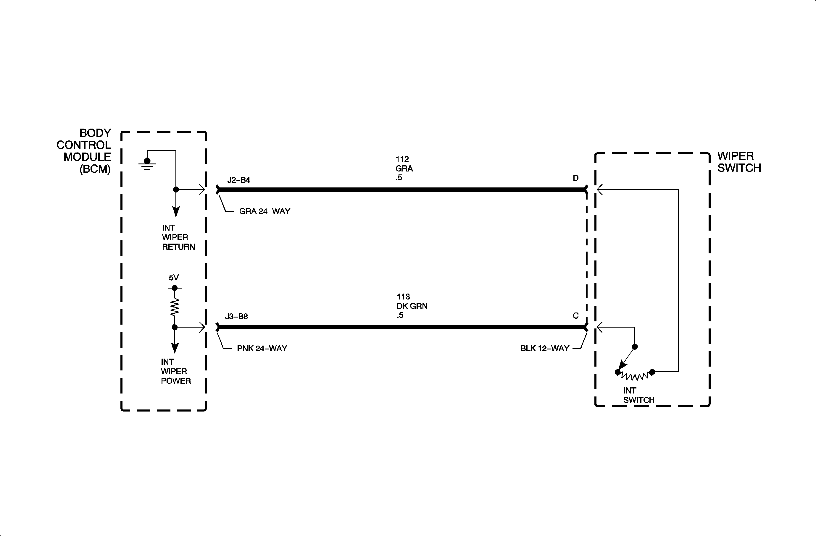
The intermittent wiper delay switch is a voltage divider connected across body
control module (BCM) inputs circuit 113 and circuit 96. The wiper relay
is energized by the BCM switching circuit 1445 to ground depending on the delay
switch position.
The intermittent wiper delay switch has 3 switch positions.
| • | Delay 1 - 2000 ohms resistance, 1 swipe every 12 seconds |
| • | Delay 2 - 1000 ohms resistance, 1 swipe every 7 seconds |
| • | Delay 3 - 500 ohms resistance, 1 swipe every 2 seconds |
DTC Parameters
| • | The ignition is in the RUN or ACC position. |
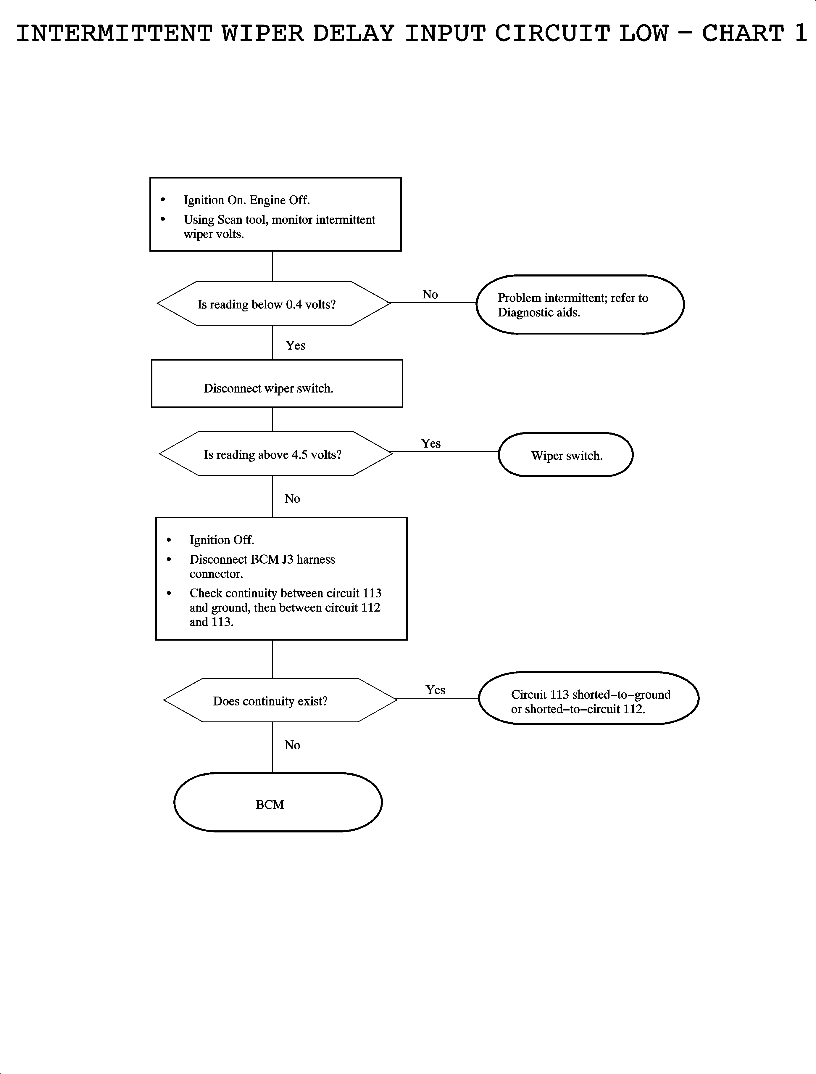
| • | Circuit 113 is shorted-to-ground. |
Diagnostic Aids
| • | Inspect the wiring harness for damage. Check for broken or chaffed insulation. |
| • | If a fault is suspected to be intermittent, wiggling the harness wiring
may help in locating the fault. |


