Info - Timing Chain Design Change and Revised Service Procedures

| Subject: | Service Information -- Timing Chain Design Change and Revised Service Procedures |
| Models: | 2000-2003 Saturn L-Series with 2.2L Engine (VIN F -- RPO L61) |
| 2002-2003 Saturn VUE with 2.2L Engine (VIN D -- RPO L61) |
| 2003 Saturn ION Vehicles |
| Attention: | General Manager, Fixed Operations Manager, Technician |
Purpose
The purpose of this bulletin is to communicate updated service procedures to the timing chain and timing chain oiling nozzle due to design changes that have been made to both components. All timing chain kits now available in service will include the oiler nozzle. This new nozzle has higher flow rate characteristics that will increase oil flow to the timing chain under low RPM operating conditions. Whenever replacing a timing chain, it is important to replace the oiler nozzle.
Prior edition Service Manuals for the above listed vehicles refer to the timing chain index links being colored "silver" and "copper." With the implementation of the newer design chain and oiler assembly, the index link colors have changed. In order to avoid confusion, the service procedure text has been modified to refer to the index links as two common colored and one unique colored link. Please use the procedure in this bulletin to replace all previously issued Service Manuals.
The eSI website will be updated immediately and future Service Stall System SI CD releases will include this and other Service Manual updates.
Service Procedure
Removal Procedure
- Disconnect negative battery cable. Refer to Battery Negative Cable Disconnect/Connect in the appropriate model and model year Engine Service Manual.
- Raise and support the vehicle. Refer to Lifting and Jacking the Vehicle in the General Information section of the appropriate model and model year Service Manual.
- Remove the engine front cover. Refer to Engine Front Cover Replacement in the appropriate model and model year Engine Service Manual.
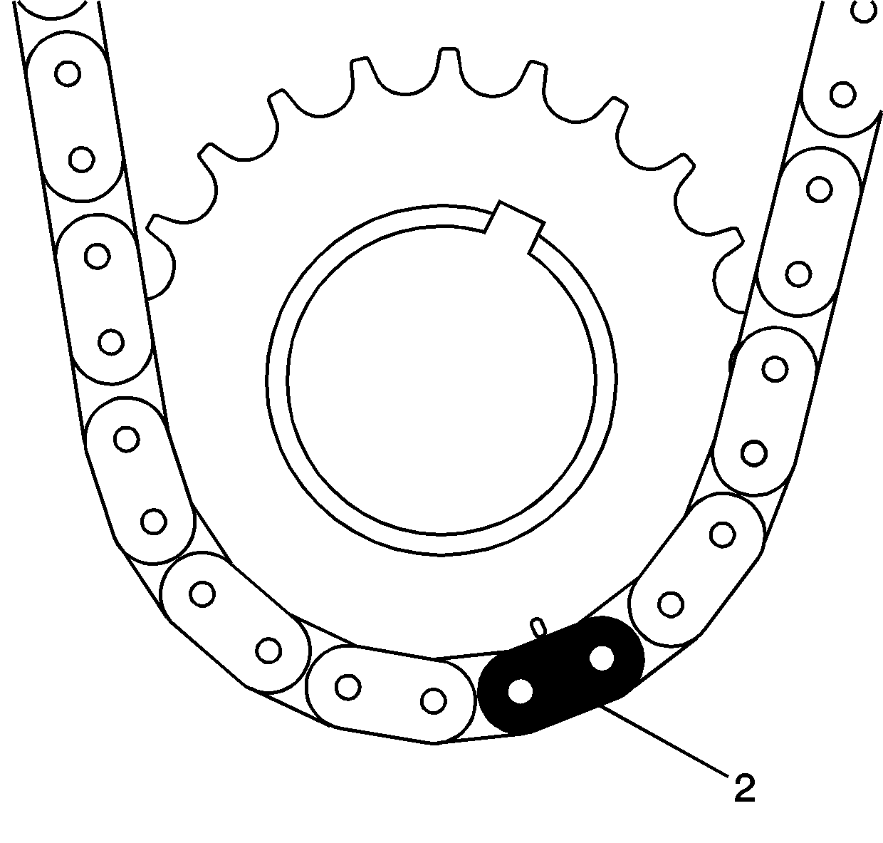
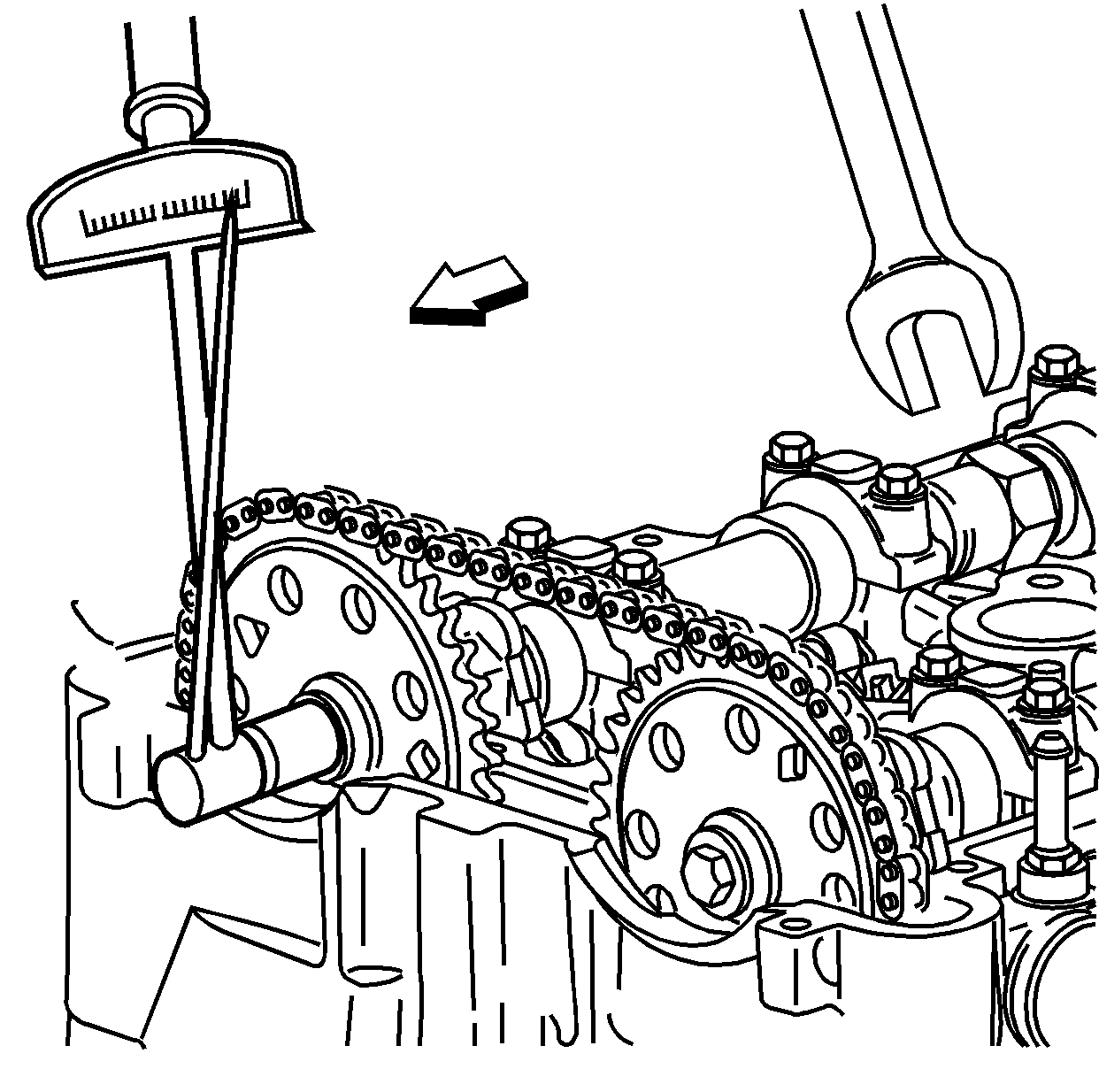
- Rotate the engine until the crankshaft sprocket mark aligns with the matching colored link (2) at the 5 o'clock position.
- Lower the vehicle.
- Remove the camshaft cover. Refer to Camshaft Cover Replacement in the appropriate model and model year Engine Service Manual.
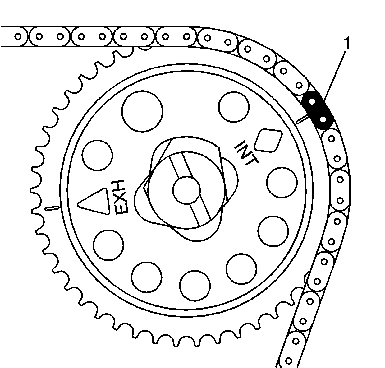
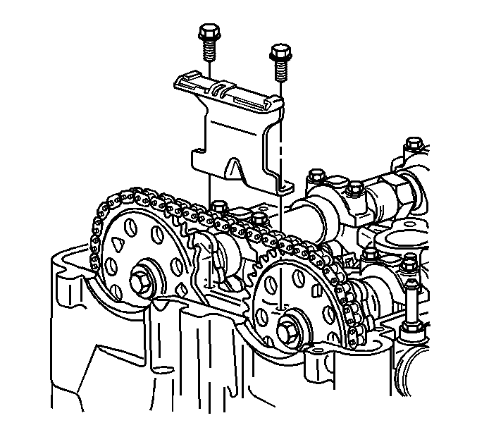
- Ensure that the INT diamond on the intake camshaft sprocket is aligned with the uniquely colored link (1) at the 2 o'clock position.
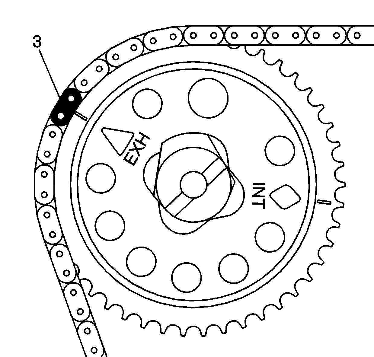
- Ensure that the EXH triangle on the exhaust camshaft sprocket is aligned with the matching colored link (3).
- Remove the timing chain tensioner.
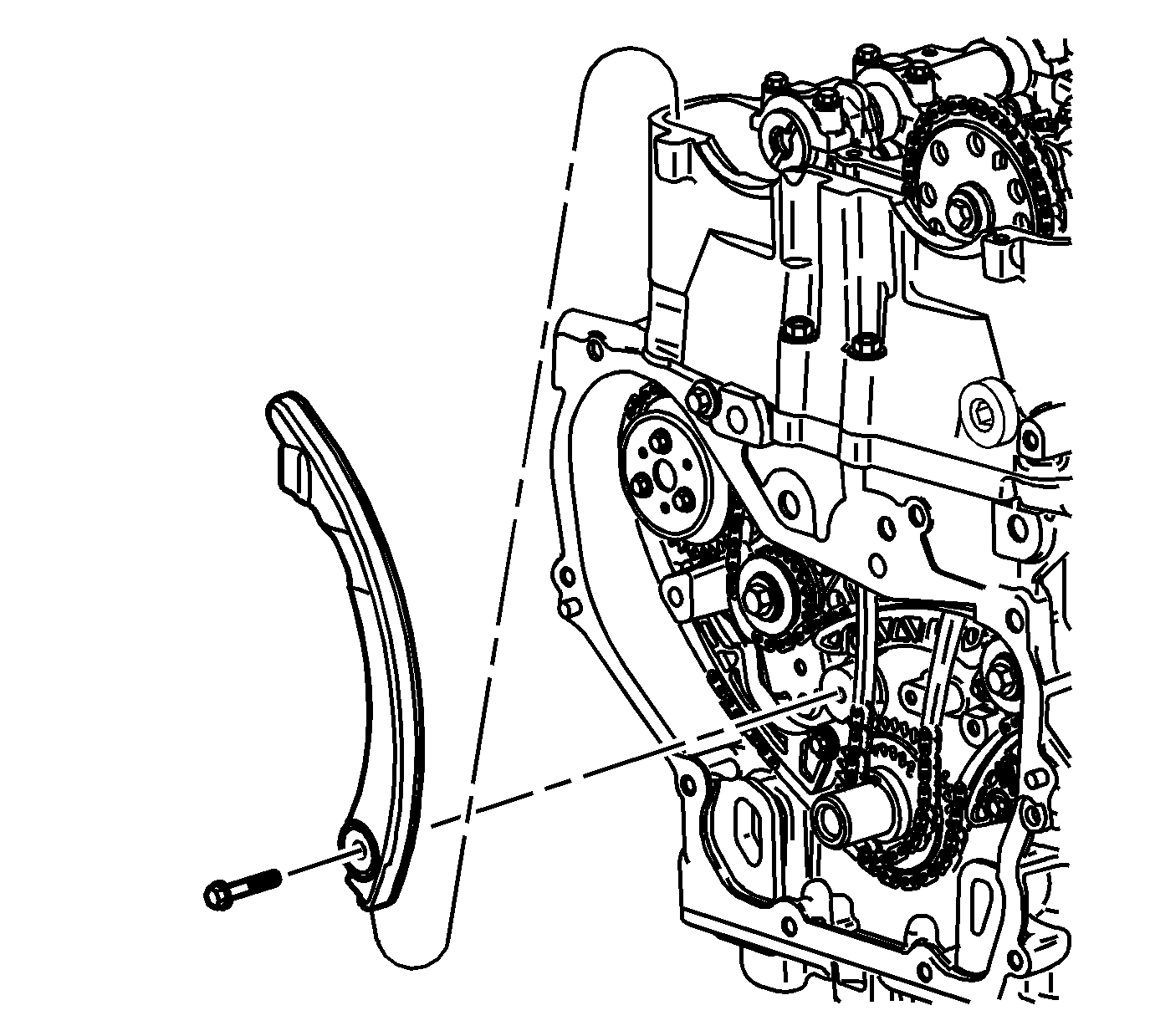
- Remove the fixed timing chain guide access plug.
- Remove the fixed timing chain guide.
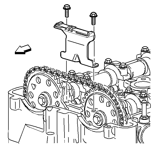
- Remove the upper timing chain guide.
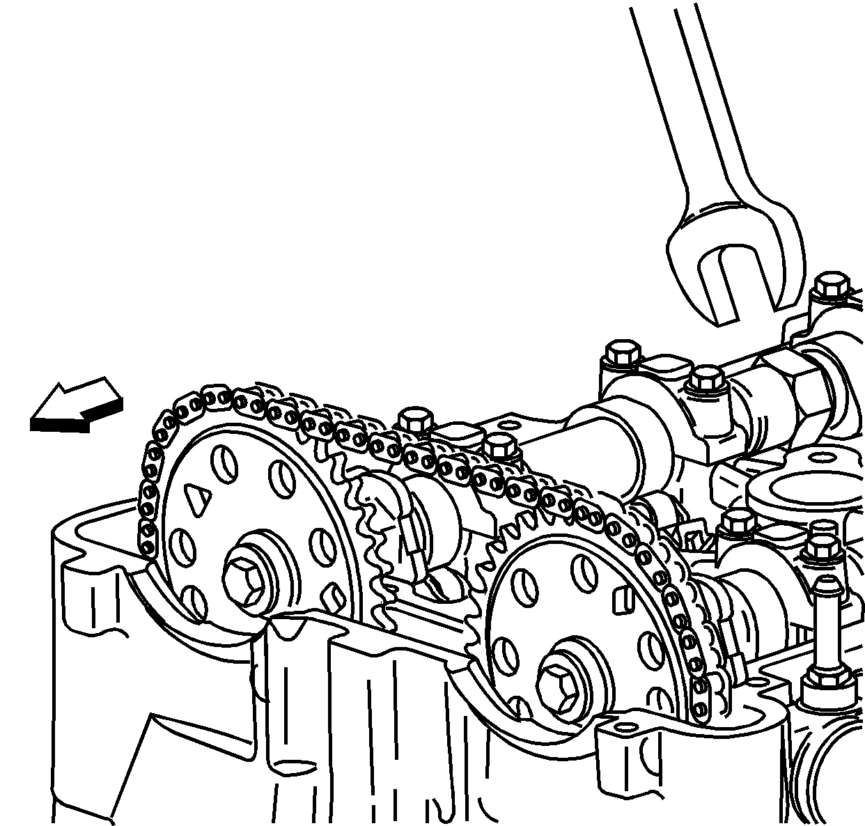
- Use a 24 mm wrench to hold the camshaft from turning.
- Remove the exhaust camshaft sprocket bolt and discard.
- Remove the exhaust camshaft sprocket.
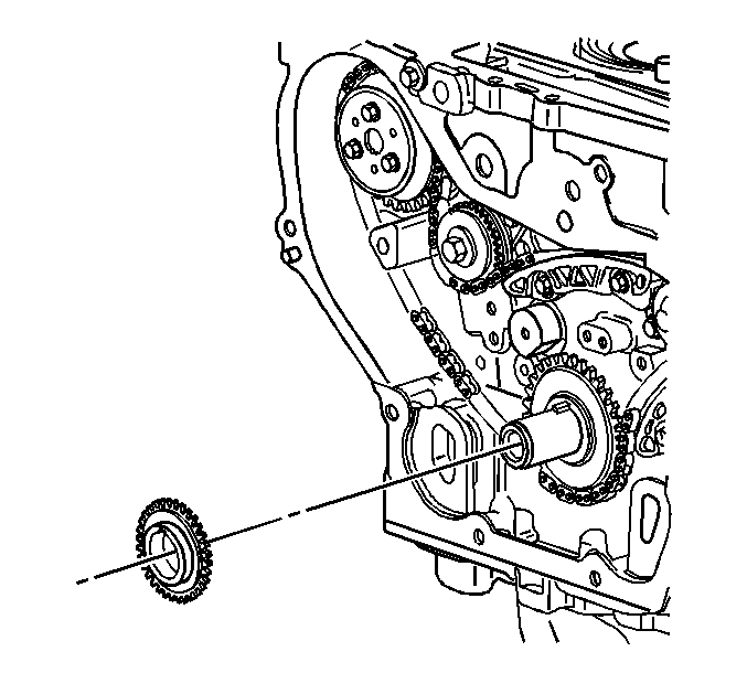
- Remove the timing chain tensioner guide.
- Remove the intake camshaft sprocket bolt and discard.
- Remove the intake camshaft sprocket.
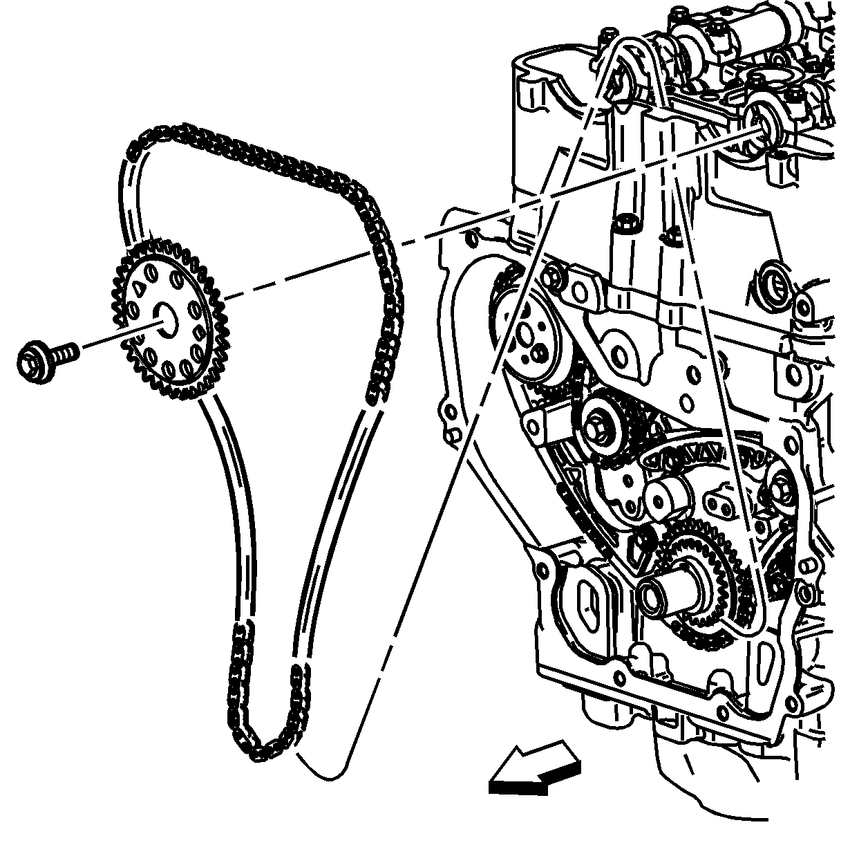
- Remove the timing chain through the top of the cylinder head.
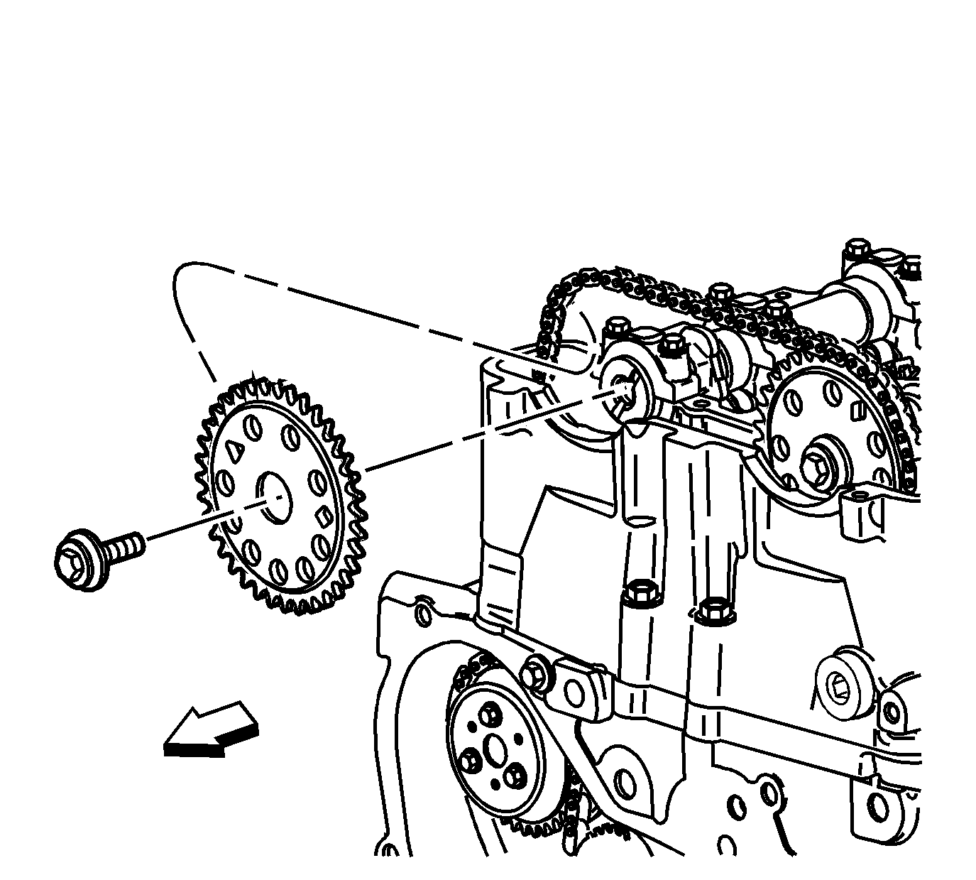
- Remove the crankshaft sprocket.
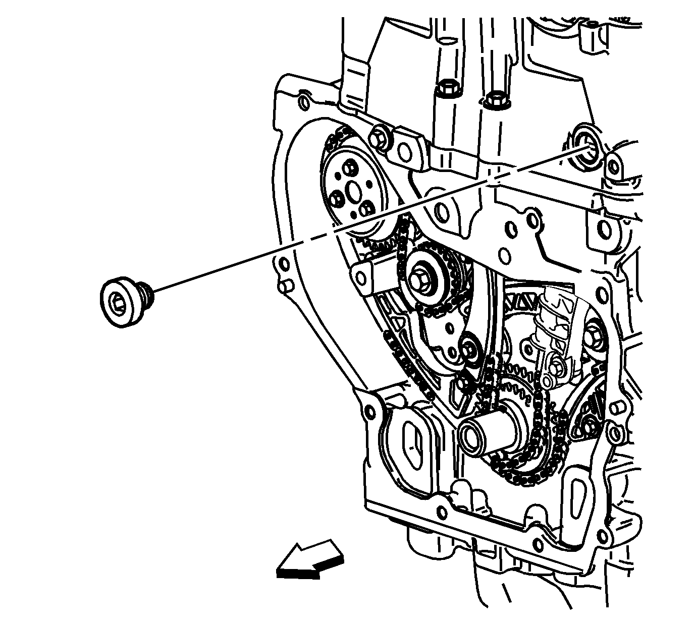
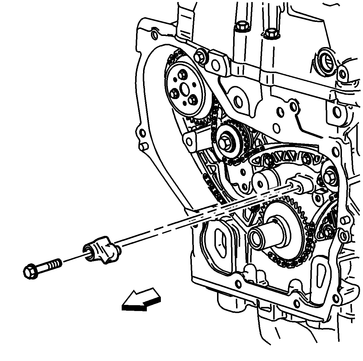
- Remove the oil nozzle and bolt.
Important: The timing chain has two matching colored links and one uniquely colored link.
Installation Procedure
- Install the oil nozzle and bolt.
- Install the crankshaft sprocket with timing mark at the 5 o'clock position.
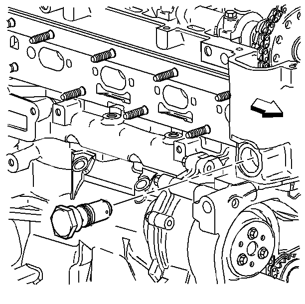
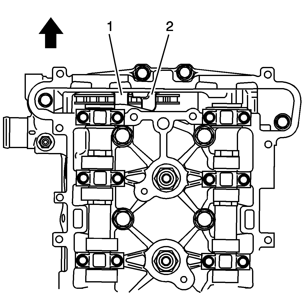
- Lower the timing chain through the opening in the top of the cylinder head. Carefully ensure that the chain goes around both sides of the cylinder block bosses (1, 2).
- Install the intake camshaft sprocket with the INT diamond at the 2 o'clock position.
- Hand tighten a NEW intake camshaft sprocket bolt. Refer to the appropriate model year and model Saturn Parts and Illustration catalog for the correct part number of the new intake camshaft sprocket bolt.
- Route the timing chain around the crankshaft sprocket with the matching colored link aligning with the timing mark.
- Route the timing chain around the intake camshaft sprocket with the uniquely colored link (1) aligning with the INT diamond.
- Install the timing chain tensioner guide through the opening in the top of the cylinder head.
- Install the exhaust camshaft sprocket with the timing chain matching colored link (3) at EXH triangle aligned at the 10 o'clock position.
- Use a 24 mm wrench to rotate the camshaft slightly, until exhaust sprocket aligns with the camshaft.
- Hand tighten the NEW exhaust camshaft sprocket bolt. Refer to the appropriate model year and model Saturn Parts and Illustration catalog for the correct part number of the new exhaust camshaft sprocket bolt.
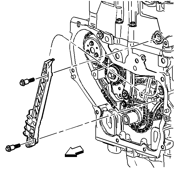
- Install the fixed timing chain guide.
- Apply sealant, Saturn P/N 21485277 (in Canada, 10953489) compound to thread and install the timing chain guide bolt access hole plug.
- Install the timing chain upper guide.
- Inspect the timing chain tensioner. If the timing chain tensioner, O-ring seal, or washer is damaged, replace the timing chain tensioner.
- Measure the timing chain tensioner assembly from end to end.
- If the timing chain tensioner is not in the compressed state, perform the following steps:
- Inspect the bore of the tensioner body for dirt, debris, and damage. If any damage appears, replace the tensioner. Clean dirt or debris out with a lint free cloth.
- Install the compressed piston assembly back into the timing chain tensioner body until it stops at the bottom of the bore. Do not compress the piston assembly against the bottom of the bore. If the piston assembly is compressed against the bottom of the bore, it will activate the tensioner, which will then need to be reset again.
- At this point, the tensioner should measure approximately 72 mm (2.83 in) from end to end (refer to illustration [a]). If the tensioner does not read 72 mm (2.83 in) from end to end (refer to illustration [a]), repeat steps 17.1 through 17.4.
- Install the timing chain tensioner.
- Use a suitable tool with a rubber tip on the end. Feed the tool down through the camshaft drive chain to rest on the timing chain. Then give a sharp jolt diagonally downwards to release the tensioner.
- Use a 24 mm wrench to hold the camshaft.
- Install the camshaft cover. Refer to Camshaft Cover Replacement in the appropriate model and model year Engine Service Manual.
- Raise and support the vehicle. Refer to Lifting and Jacking the Vehicle in the General Information section of the appropriate model and model year Service Manual.
- Install the engine front cover. Refer to Engine Front Cover Replacement in the appropriate model and model year Engine Service Manual.
- Lower the vehicle.
- Connect negative battery cable. Refer to Battery Negative Cable Disconnect/Connect in the appropriate model and model year Engine Service Manual.
Tighten
Tighten the Timing Chain Oil Nozzle Bolt to 10 N·m
(89 in-lbs)
Important: Always install NEW sprocket bolts.
Tighten
Tighten the timing chain tensioner guide bolt to
10 N·m (89 lb in).
Important: Always install NEW sprocket bolts.
Tighten
Tighten the fixed timing chain bolts to 10 N·m
(89 lb in).
Tighten
Tighten the chain guide plug to 40 N·m
(30 lb ft).
Tighten
Tighten the timing chain upper guide bolts to 10 N·m
(89 lb in).
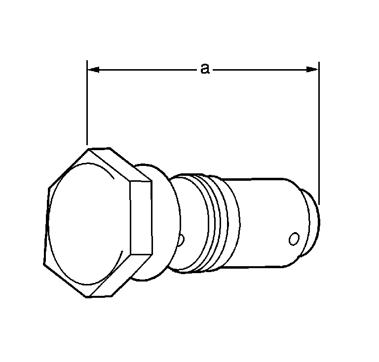
A new tensioner should be supplied in the fully compressed non-active state. A tensioner in the compressed state will measure 72 mm (2.83 in) from end to end (refer to illustration [a]). A tensioner in the active state will measure 85 mm (3.35 in) from end to end (refer to illustration [a]).
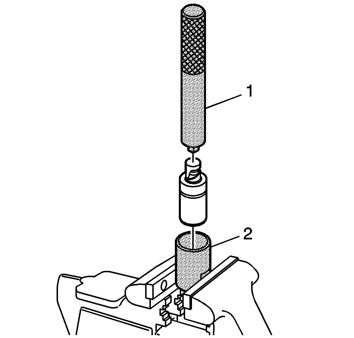
| 17.1. | Remove the piston assembly from the body of the timing chain tensioner by pulling it out. |
| 17.2. | Install the J 45027-2 (2) into a vise. |
| 17.3. | Install the notch end of the piston assembly into the J 45027-2 (2). |
| 17.4. | Using the J 45027-1 (1), turn the ratchet cylinder into the piston. |
Tighten
Tighten the timing chain tensioner to 75 N·m
(55 lb ft).
Tighten
Tighten the NEW camshaft bolts to 85 N·m
(63 lb ft) plus 30 degrees.
