Service Information Regarding Rear Seat Entertainment System (DVD) Diagnostics and Service Procedures

| Subject: | Service Information Regarding Rear Seat Entertainment System (DVD) Diagnostics and Service Procedures |
| Models: | 2002-2003 Saturn L-Series vehicles equipped with rear seat entertainment system (RPO U32) |
| Attention: | Fixed Operations Manager and Technician |
This bulletin (04-08-44-008A) is identical to Saturn bulletin 02-I-01A previously published. This bulletin is being issued for electronic purpose only and the paper bulletin (02-I-01A) should not be discarded.
Purpose
The purpose of this bulletin is to provide the following information to diagnose and service the 2002-2003 Saturn L-Series rear seat entertainment system.
| • | Rear Seat Entertainment System Schematics |
| • | Rear Seat Entertainment Connector Face Views |
| • | Rear Seat Entertainment Component Locations |
| • | Rear Seat Entertainment Diagnostic Table |
| • | Rear Seat Entertainment General Descriptions |
| • | Rear Seat Entertainment Removal and Installation Procedures |
| • | Parts Information (1st and 2nd Design) |
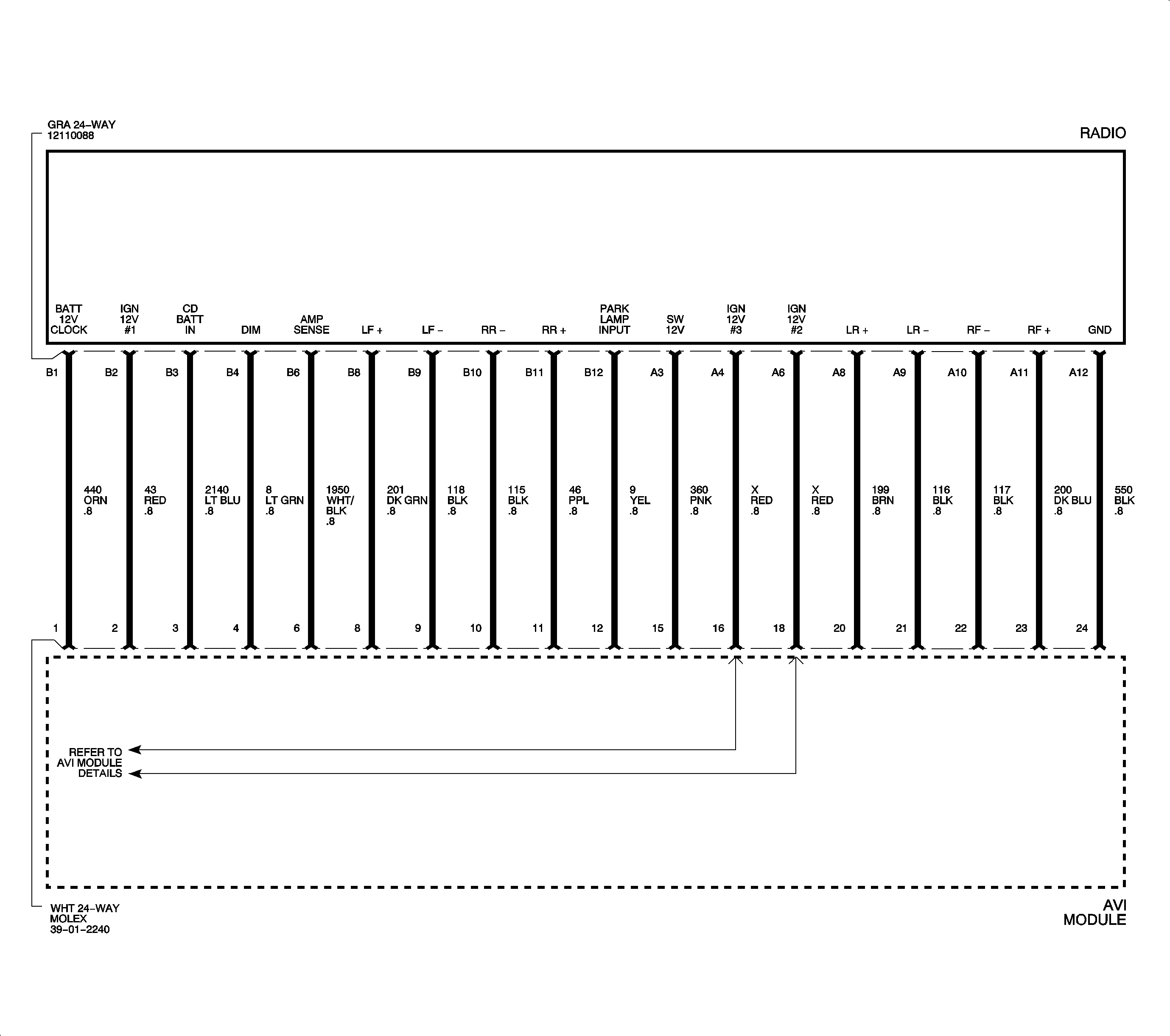
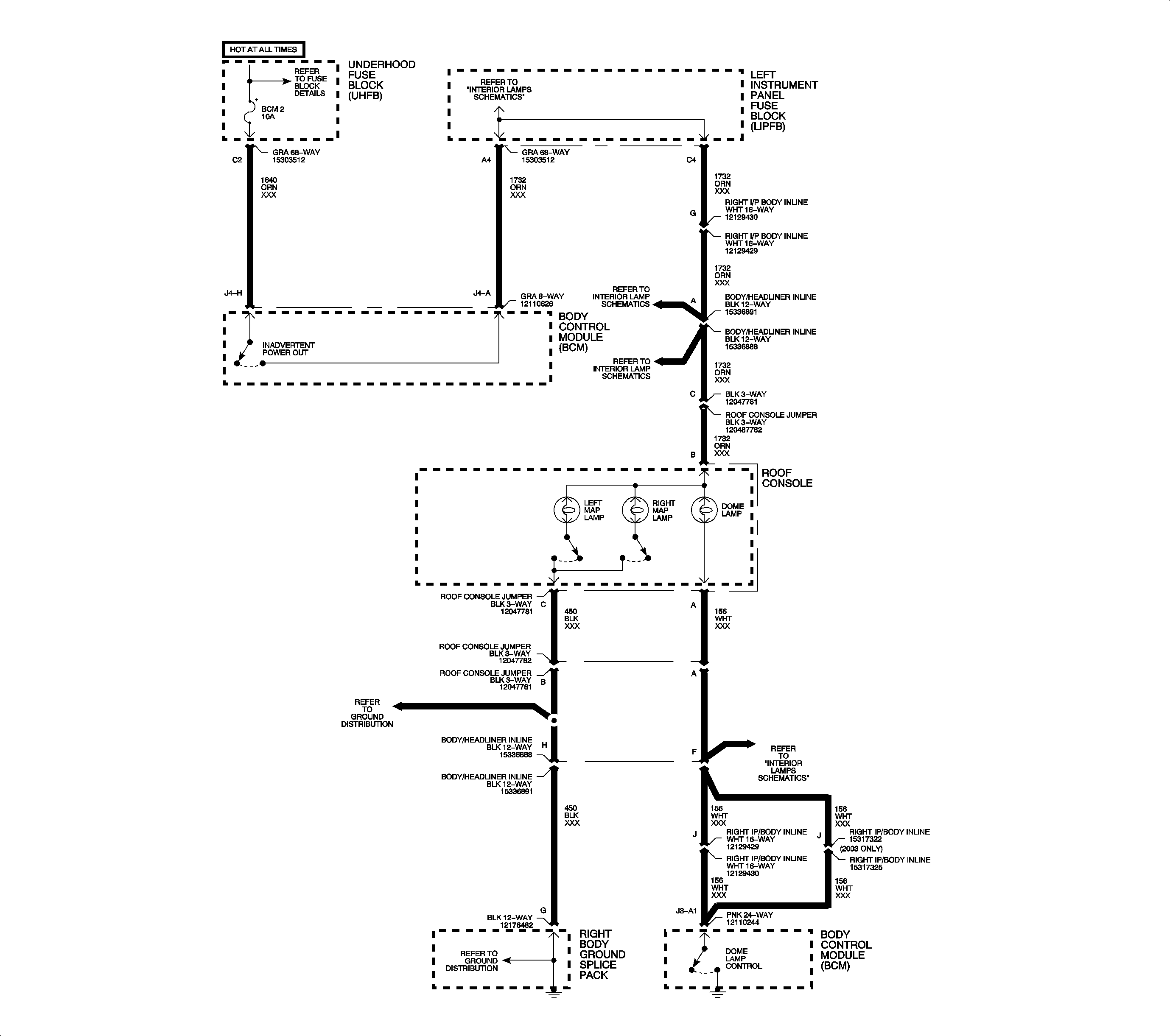
REAR SEAT ENTERTAINMENT SYSTEM SCHEMATICS
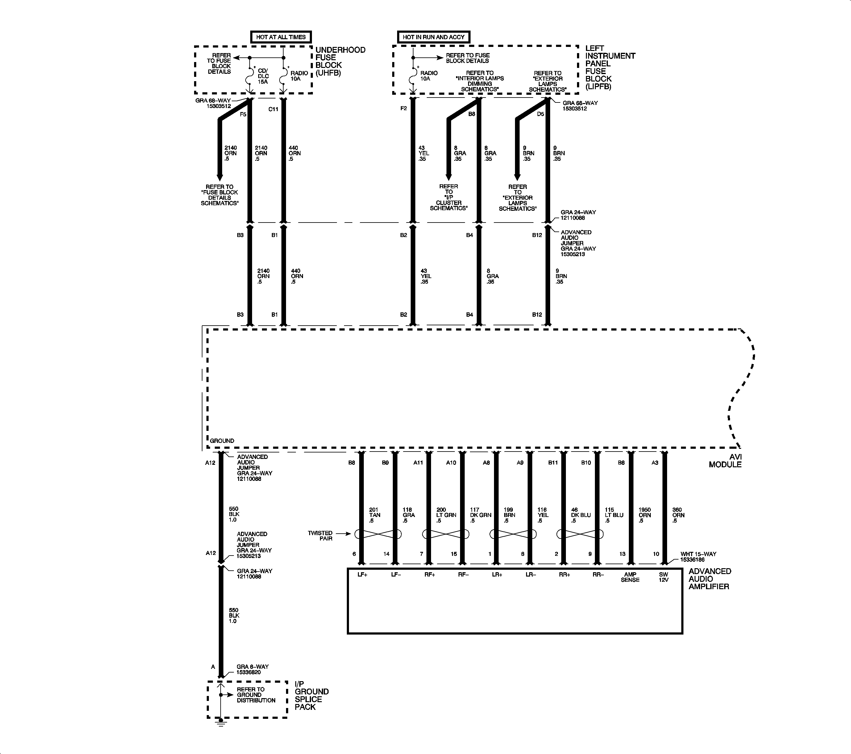
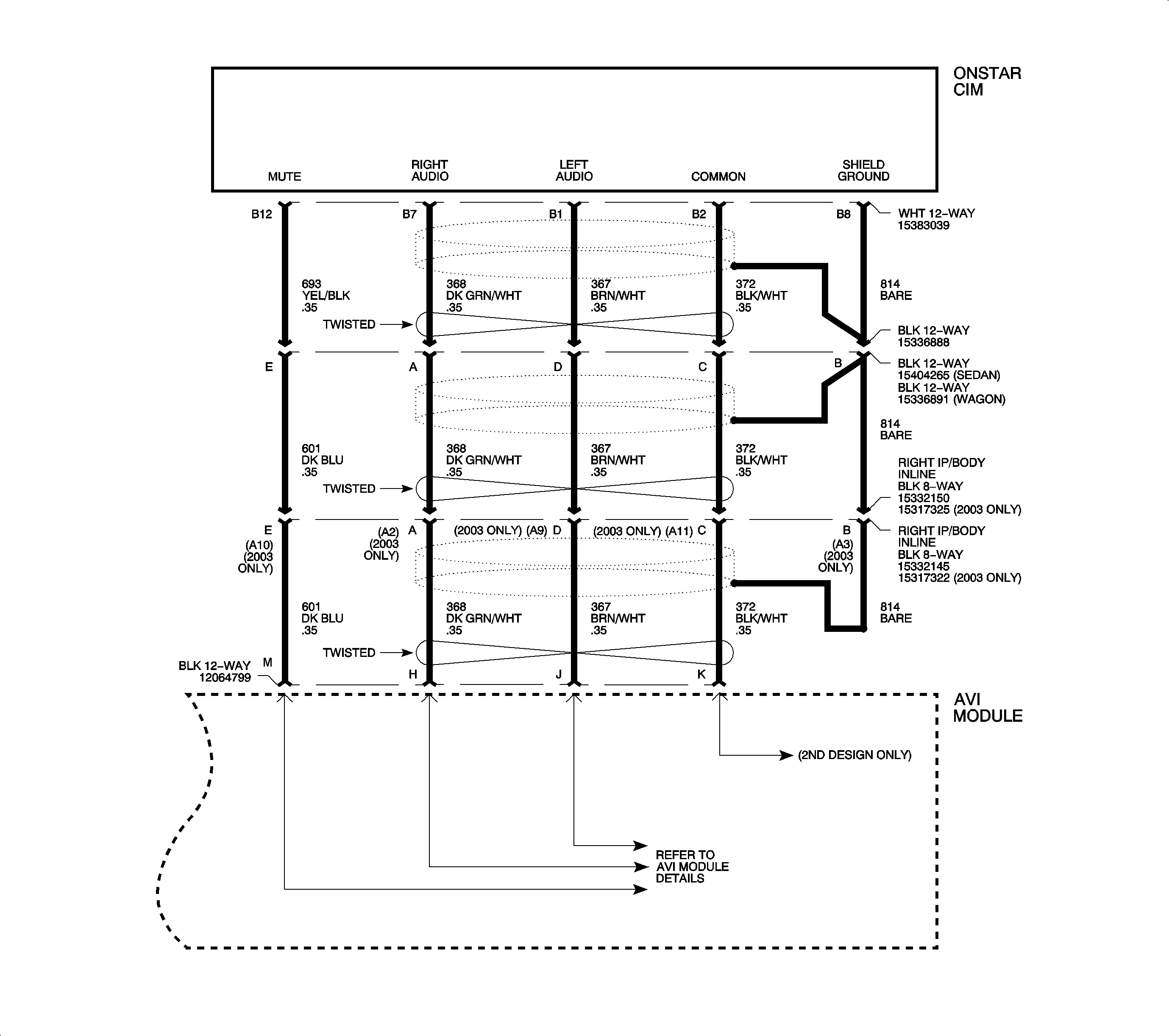
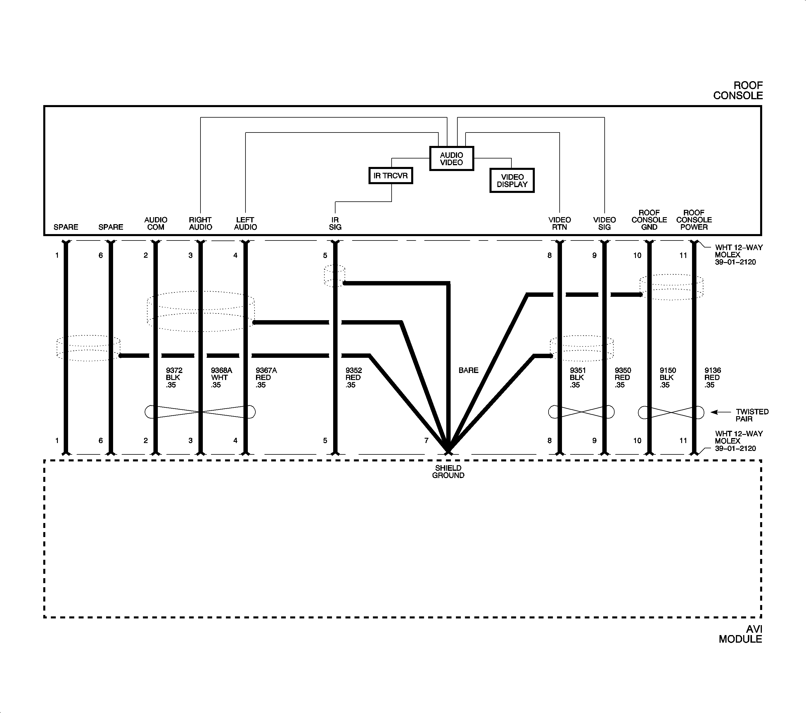
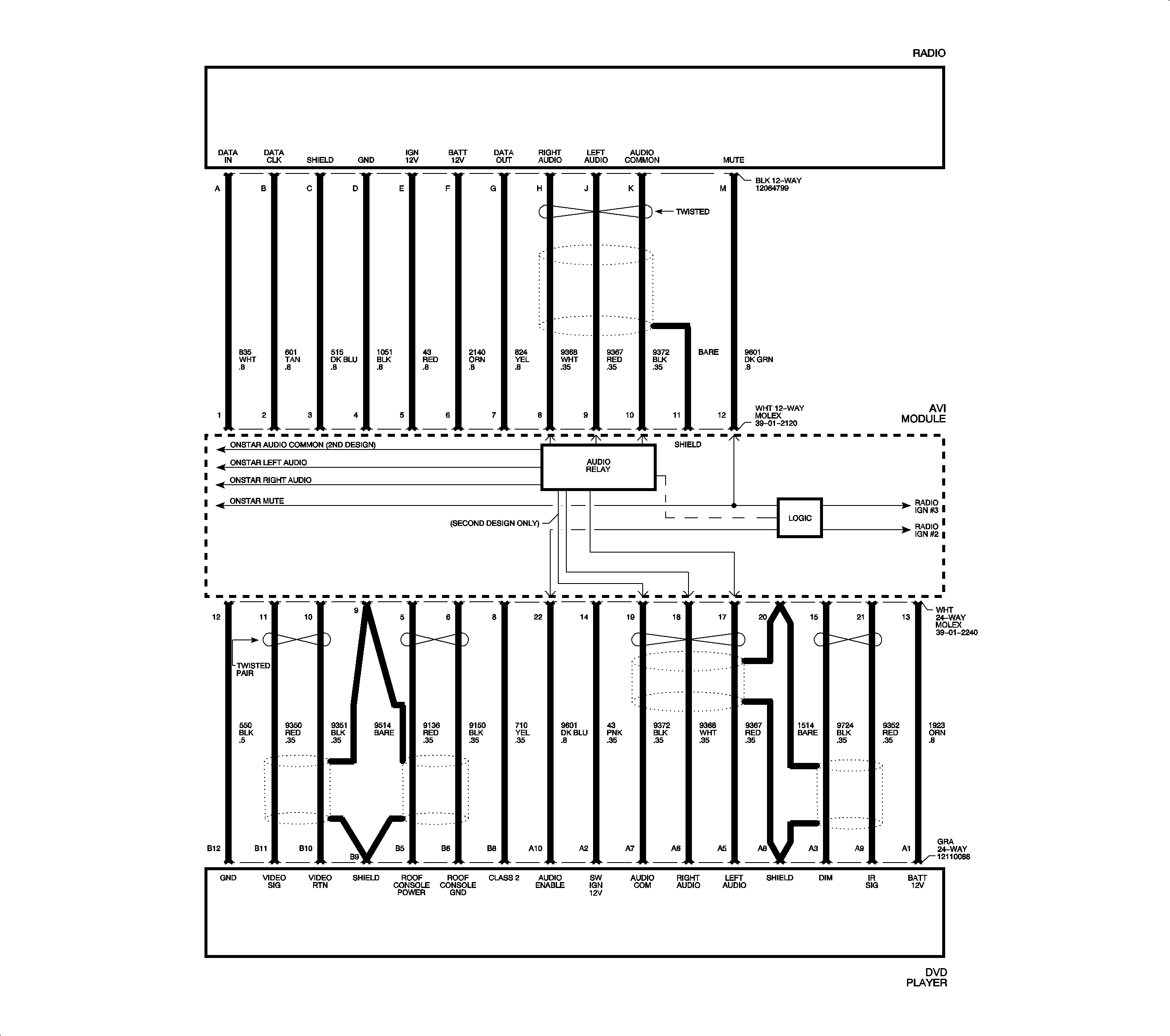
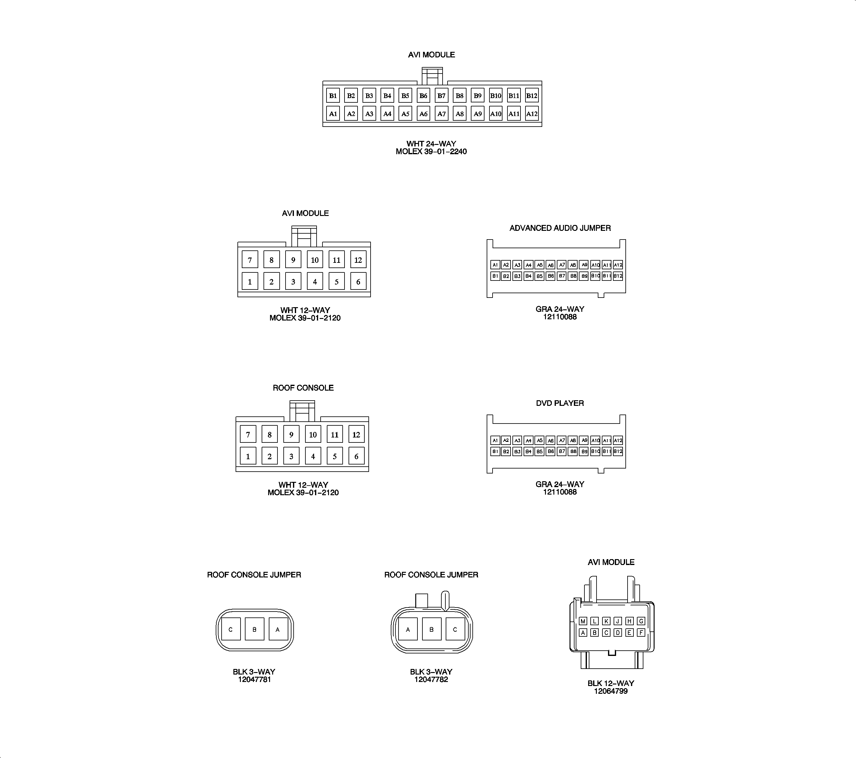
REAR SEAT ENTERTAINMENT CONNECTOR FACE VIEWS
REAR SEAT ENTERTAINMENT COMPONENT LOCATIONS
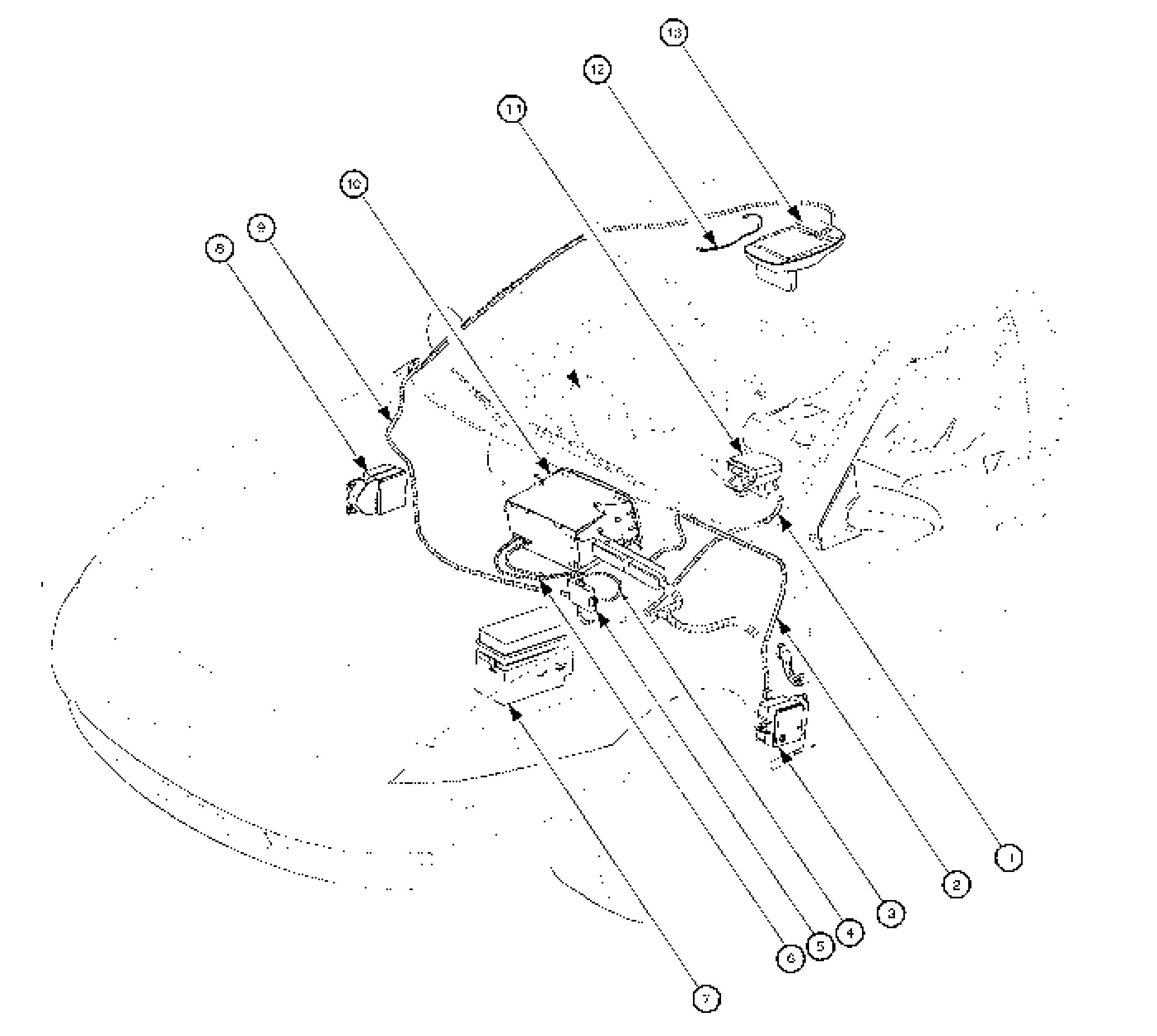
- Digital Video Disc (DVD) Player Harness
- Advanced Audio Jumper
- Left Instrument Panel Fuse Block (LIPFB)
- AVI Module to Radio 12-Way Harness
- AVI Module
- AVI Module to Radio 24-Way Harness
- Underhood Fuse Block (UHFB)
- Right Instrument Panel Fuse Block (RIPFB)
- Roof Console Harness
- Radio
- Digital Video Disc (DVD) Player
- Dome Lamp Jumper Harness
- Roof Console
REAR SEAT ENTERTAINMENT SYSTEM CHECK CHART
DVD Players
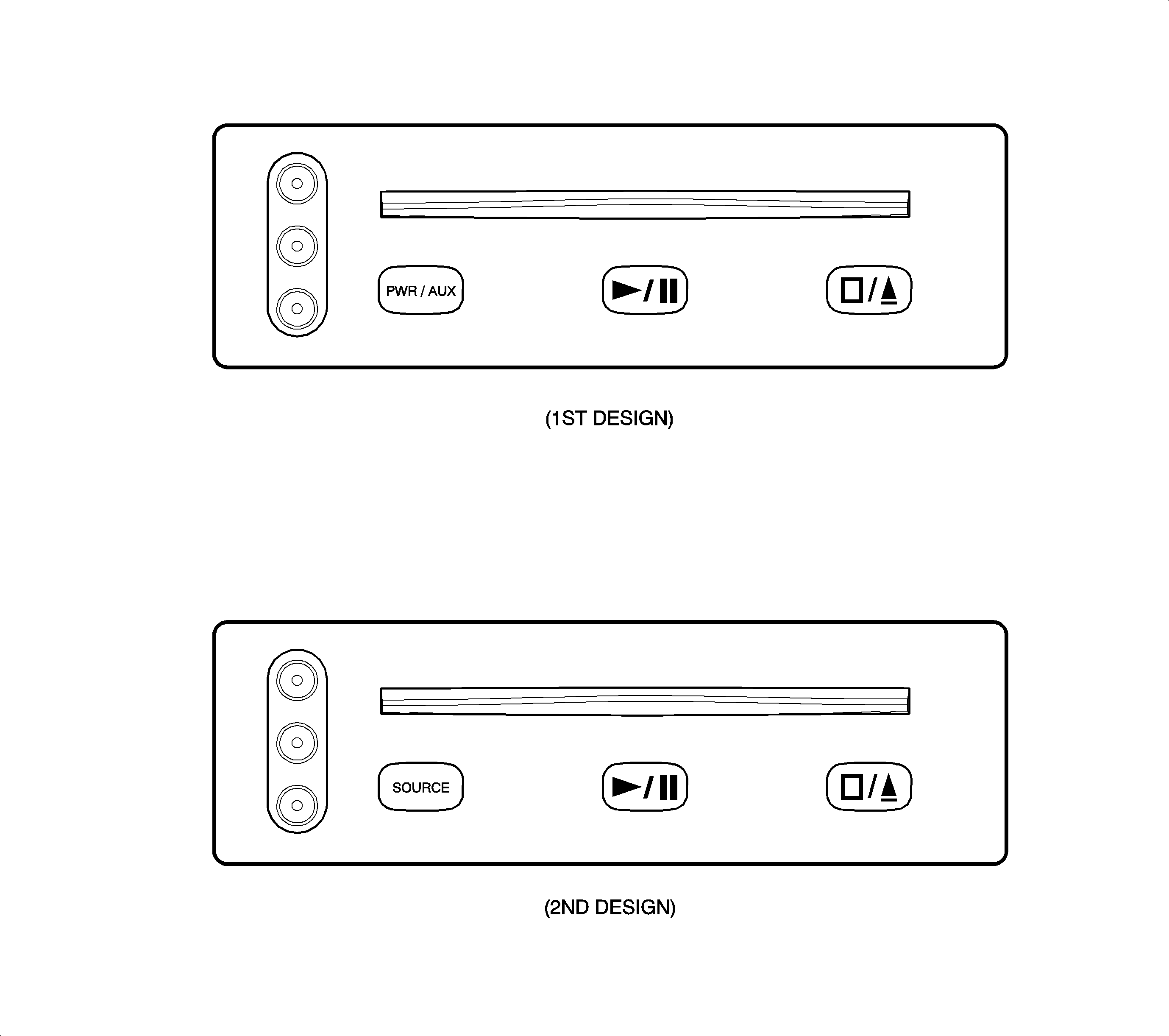
Action | Verify |
|---|---|
1. With Ignition switch in ACC or RUN, fold Roof Console Video Display screen down. | DVD player and roof console power up and the video display activates. With no DVD playing, and no auxiliary device providing video signals, the video display shows a blue screen. The DVD player always powers up with auxiliary video input active first (AUX Mode). |
2. Insert a Digital Video Disc (DVD) into the DVD Player. | DVD player accepts the CD. After a few seconds, the DVD player switches from AUX mode to DVD mode and the beginning part of the DVD is displayed on the video display. Important: DVDs may not have video sound during the beginning (such as copyright notices). Allow the DVD enough time to begin playing video sound. This may occur once a main menu appears, or when the main program (movie) begins. When video sound begins, the radio switches to video AUX mode and video sound plays through the vehicle speakers. |
3. Press PWR/AUX or SOURCE button. | Video system switches to AUX mode, if an auxiliary device is connected and providing video signals to the DVD player. Check Auxiliary video inputs by connecting a video device (such as a camcorder or video game unit) to the RCA video jacks. Auxiliary video is shown on the roof console video display and sound is heard through the vehicle speakers. |
4. Press Play/Pause button. | DVD player and video display begin playing the DVD program (movie). |
5. Press Play/Pause button again. | Video system pauses DVD program (movie) play and freezes the current frame on the roof console video display. |
6. Press Play/Pause button again. | Video system begins playing the DVD program (movie) from the place it was paused. |
7. Press Stop/Eject button. | The current DVD being played is stopped. The roof console video display shows a blue screen. |
8. Press Stop/Eject button again. | DVD currently loaded in the DVD player is ejected. |
Remote Controls
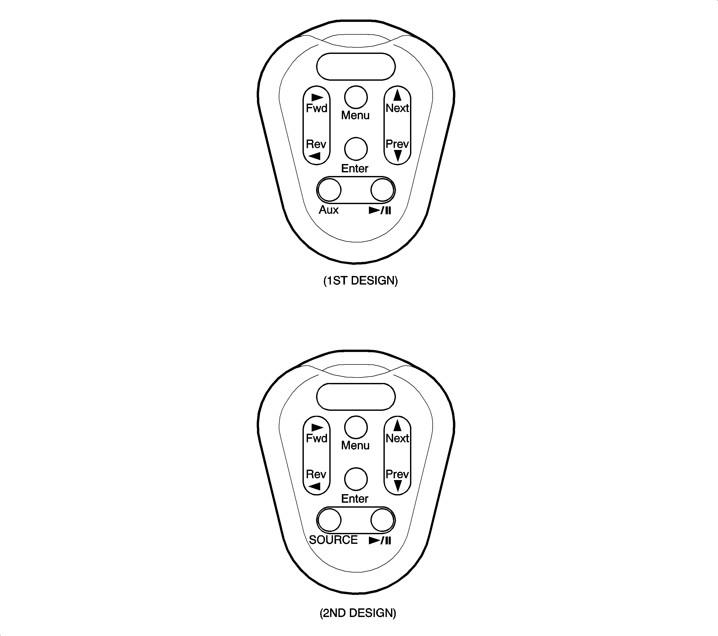
Action | Verify |
|---|---|
1. Insert a Digital Video Disc (DVD) into the DVD Player. | DVD player accepts the CD. After a few seconds, the DVD player switches from AUX mode to DVD mode and the beginning part of the DVD is displayed on the video display. Important: DVDs may not have video sound during the beginning (such as copyright notices). Allow the DVD enough time to begin playing video sound. This may occur once a main menu appears, or when the main program (movie) begins. |
2. Press Play/Pause button. | DVD program (movie) begins playing. Important: Some DVDs begin playing the program (movie) immediately after the copyright notice. This step may not be required to begin playing the DVD program. |
3. Press Play/Pause button again. | Video system pauses DVD play and freezes the current frame on the roof console video display. |
4. Press Play/Pause button again. | Video system begins playing the DVD program (movie) from the place it was paused. |
5. Press Next. | The next DVD program (movie) scene begins playing. |
6. Press Prev. | The previous DVD program (movie) scene begins playing. |
7. Press and hold Fwd. | Video system quickly advances forward through the DVD program (movie). Note: Video sound is muted while fast forwarding a DVD. The DVD information is read in wider spaced "steps" than during normal play so program (movie) frames are flashed on the video screen briefly as the DVD is fast forwarded. Releasing the Fwd button resumes normal DVD play. |
8. Press and hold Rev. | Video system quickly reverses through the DVD program (movie). Note: Video sound is muted while fast reversing a DVD. The DVD information is read in wider spaced "steps" than during normal play so program (movie) frames are flashed on the video screen briefly as the DVD is fast reversed. Releasing the Rev button resumes normal DVD play. |
9. Press Menu. | For DVDs with Menu features, the DVD menu will be displayed. The DVD program (movie) continues to play in the background on some DVDs. |
10. Press Fwd (right arrow). | Navigates to the right in the DVD menu. |
11. Press Rev (left arrow). | Navigates to the left in the DVD menu. |
12. Press Next (up arrow). | Navigates upward in the DVD menu. |
13. Press Prev (down arrow). | Navigates downward in the DVD menu. |
14. Press Enter. | Picks and activates the current DVD menu selection. |
15. Press AUX or SOURCE button. | Video system switches to AUX Mode, if an auxiliary device is connected and providing video signals to the DVD player. Check auxiliary video inputs by connecting a video device (such as a camcorder or video game unit) to the RCA video Jacks. Auxiliary video is shown on the roof console video display and sound is heard through the vehicle speakers. |
16. Press Play/Pause button. | Video system switches back to DVD Mode. Video system begins playing the DVD program (movie) at the same place it was prior to switching out of DVD mode. |
17. Press and hold Play/Pause button for more than 3 seconds. | Video system powers off. |
REAR ENTERTAINMENT SYMPTOM DIAGNOSTIC TABLE
SYMPTOM | DIAGNOSTIC PROCEDURE |
|---|---|
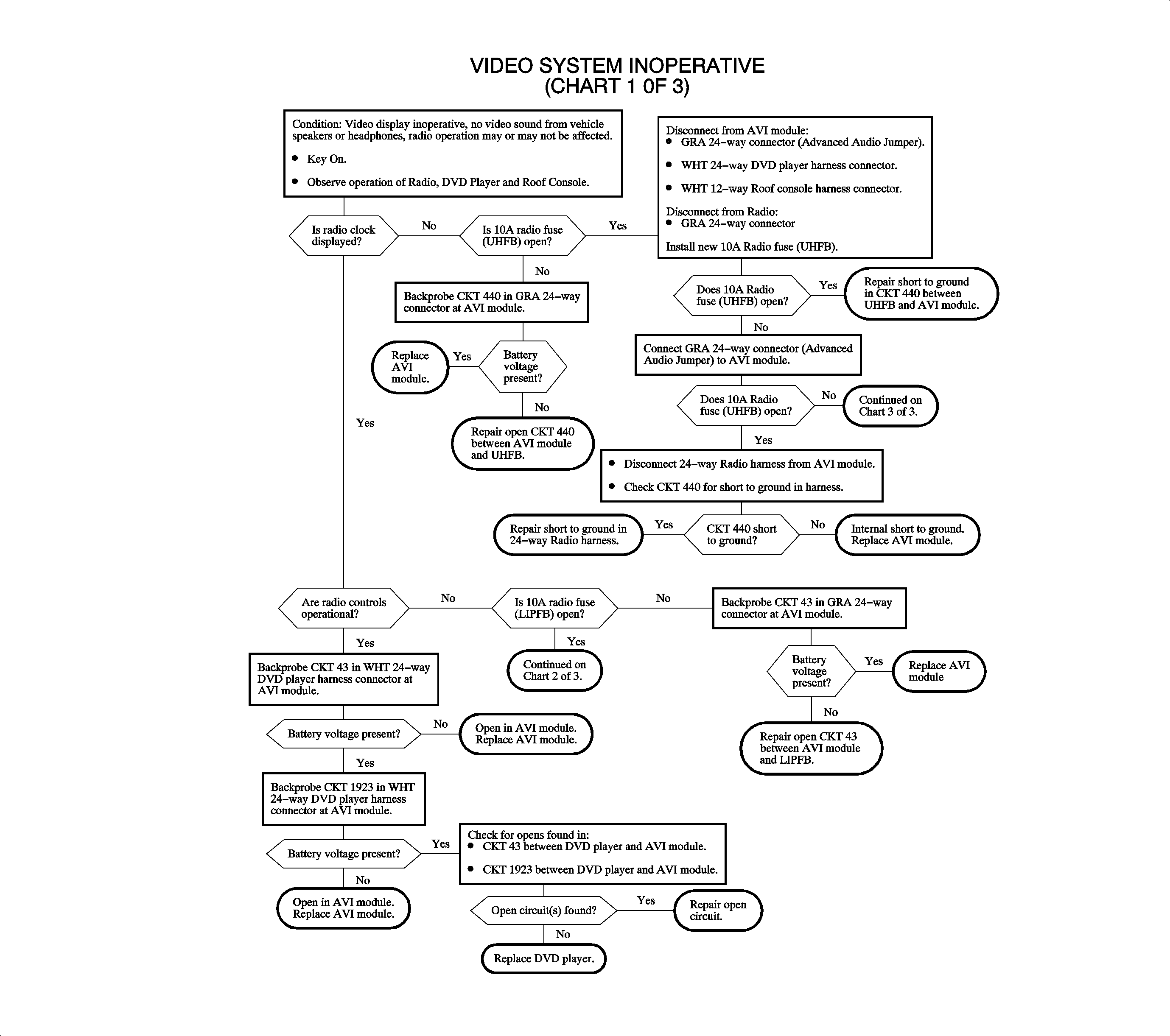
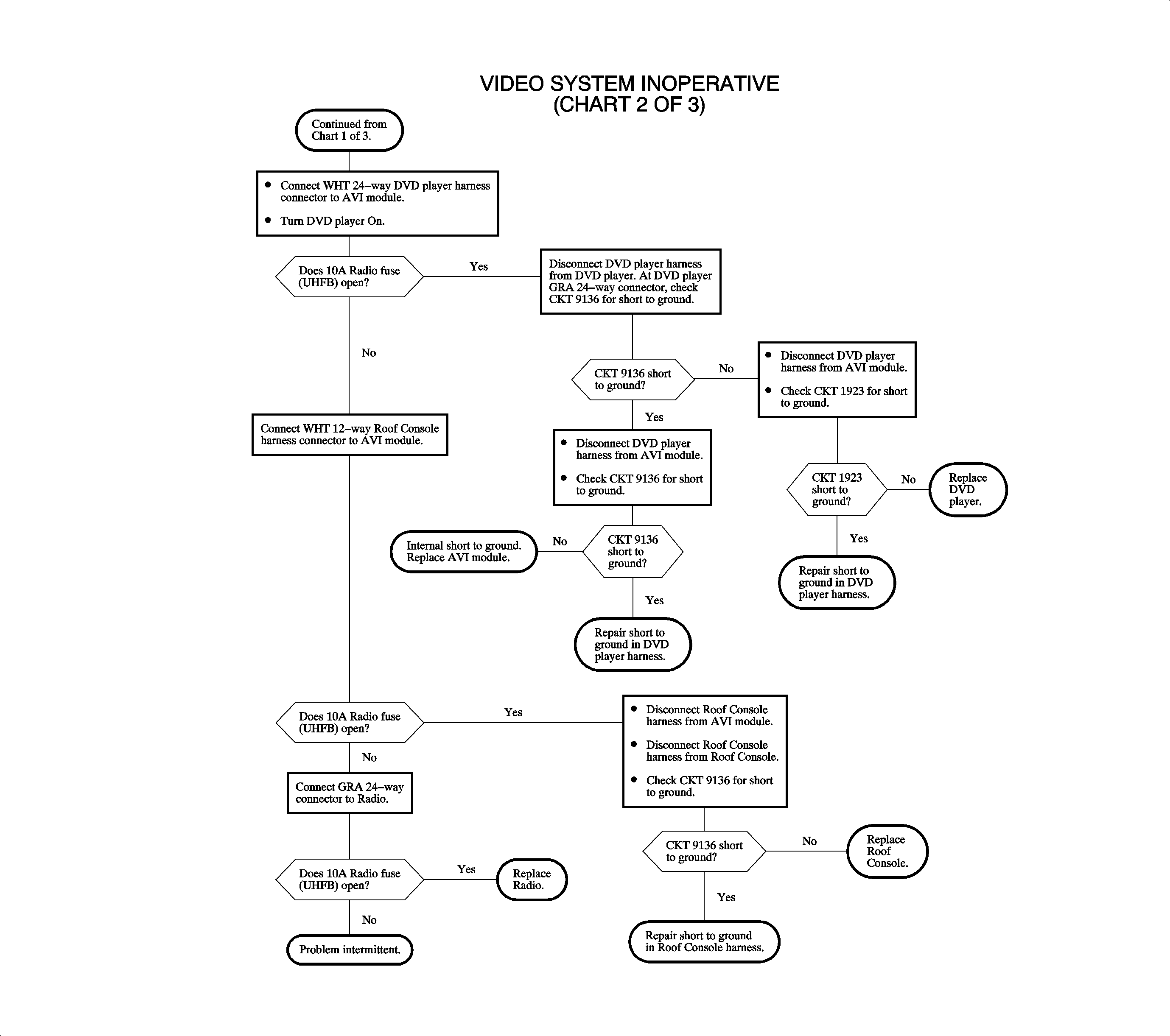
Video display is blank or dark, no video sound, radio may or may not be affected. | Chart - Video System Inoperative |
Video display blank or dark, Video sound from vehicle speakers OK. | Chart - Video Display Inoperative |
One or more speakers inoperative with both video sound and radio sound. | Chart - Video and Radio Sound - One or More Speakers Inoperative |
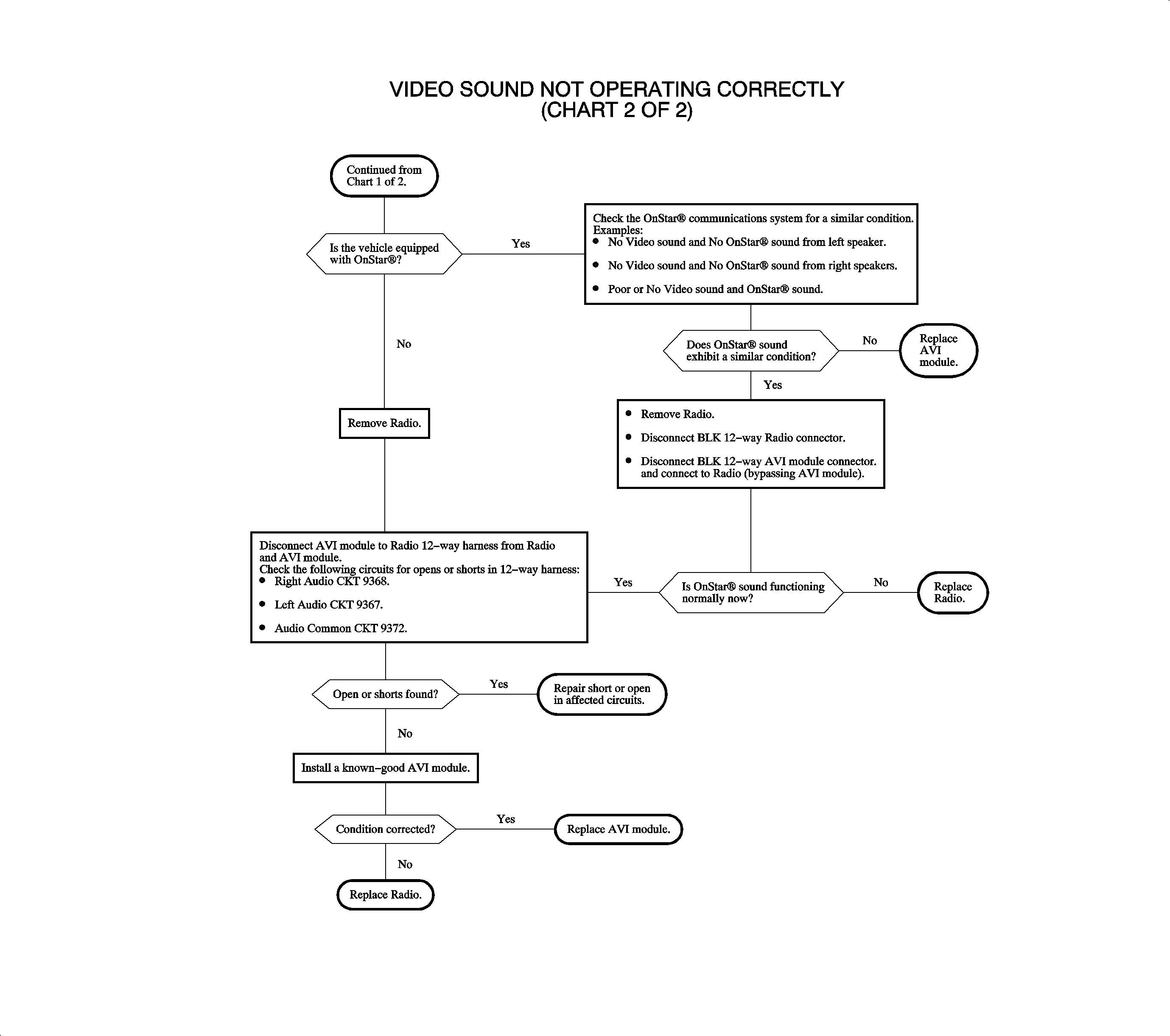
Video sound does not come through the left and/or right side of the vehicle speakers. | Chart - Video Sound Not Operating Correctly |
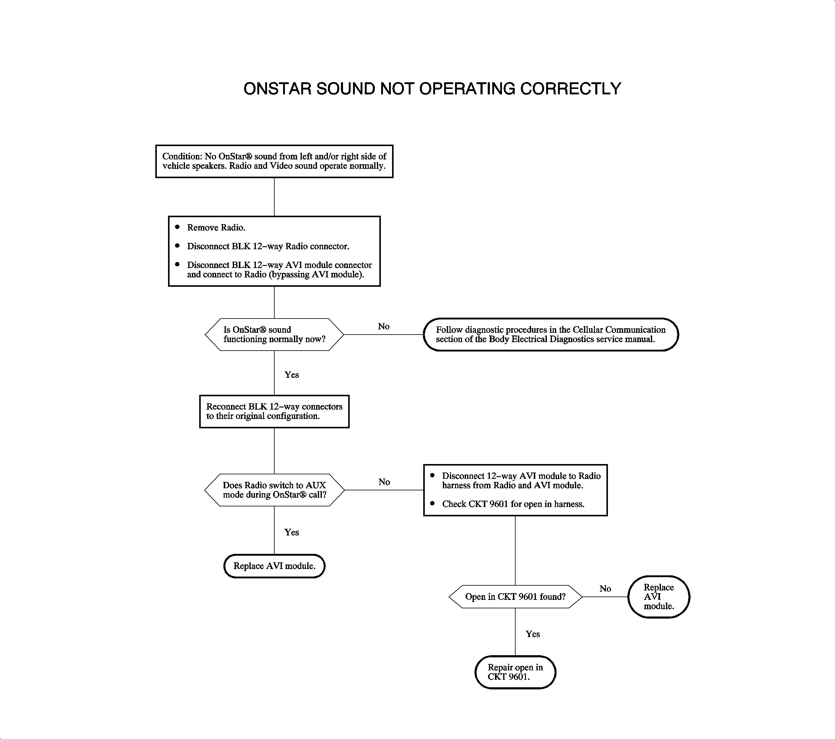
OnStar® sound does not come through left and/or right side of vehicle speakers. Radio and video sound OK. | Chart - OnStar® Sound Not Operating Correctly |
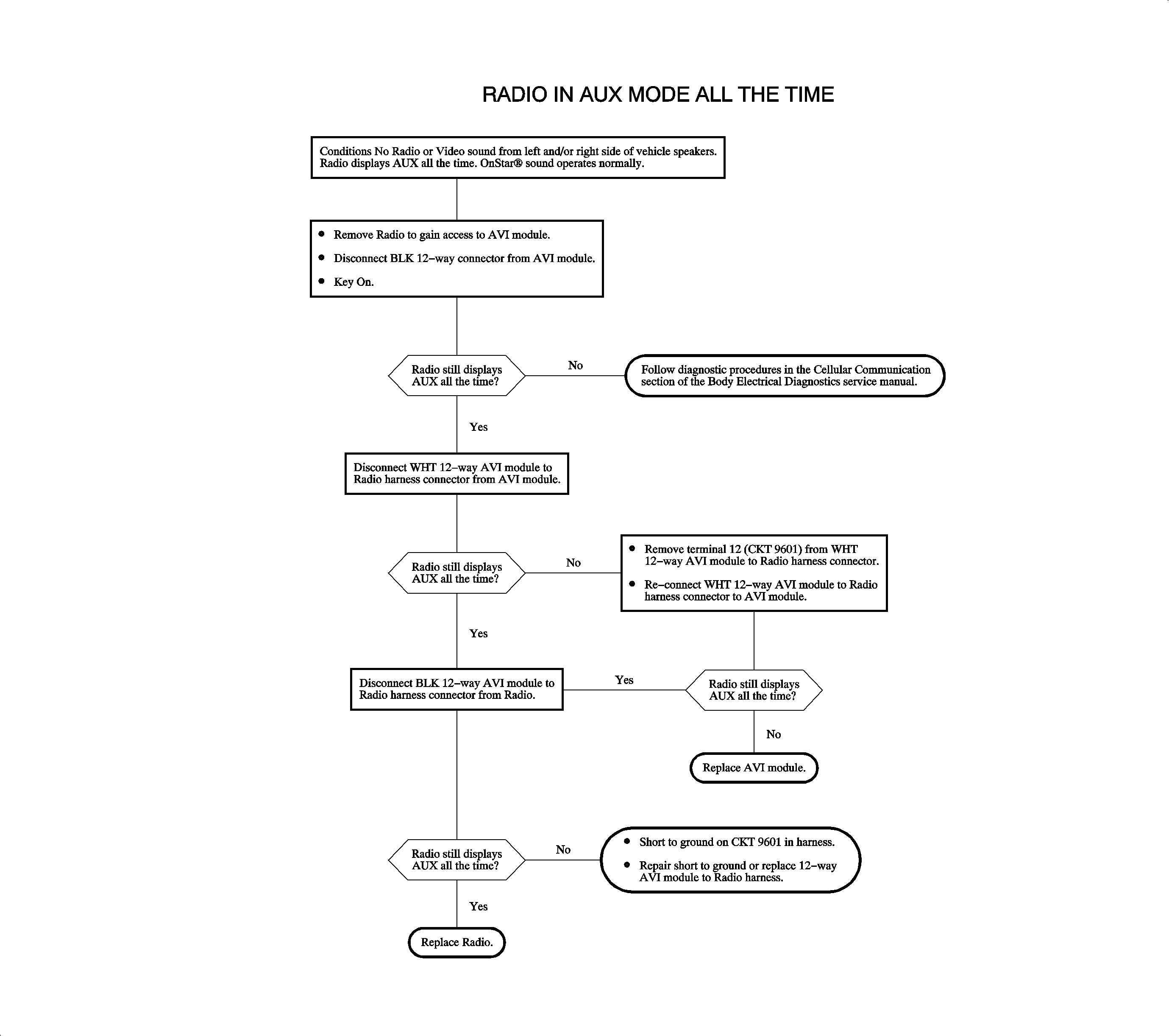
Radio in AUX mode All The time, OnStar® sound operates normally, other radio sound is inoperative. | Chart - Radio in AUX Mode All The Time |
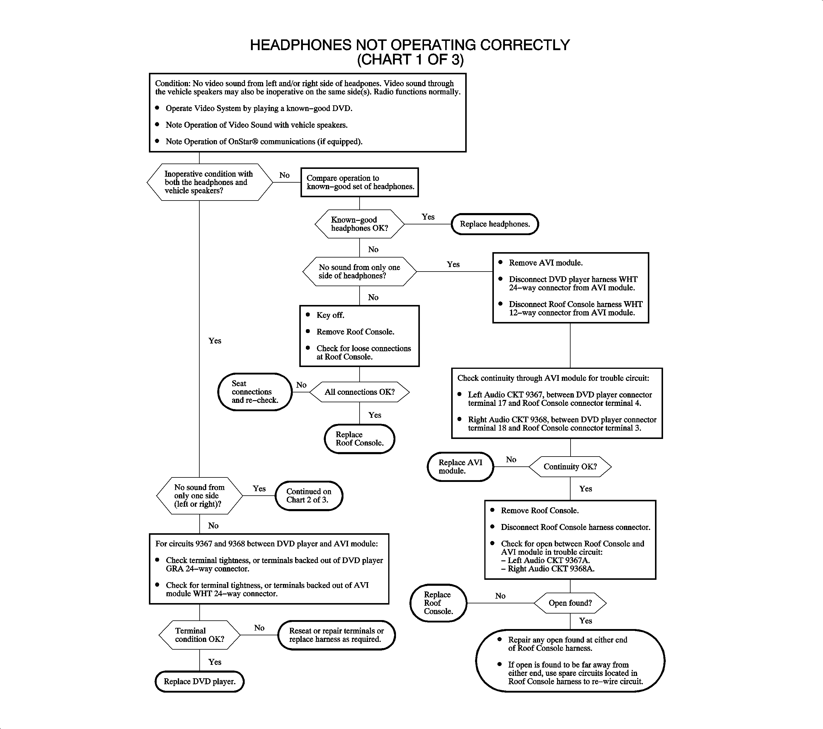
Headphones not operating correctly, video sound through the vehicle speakers may be inoperative on the same side, other radio sound operates normally. | Chart - Headphones not Operating Correctly |
Wireless remote control inoperative, video display OK. | If Wireless Headphones are also inoperative, check for loose connections in the roof console. If OK, replace roof console. Check remote control batteries and replace if needed. Check remote control operation with a known-good unit. Replace remote control if known-good remote control functions normally. If just the remote control is inoperative, CKT 9352 may be open or shorted to ground or voltage between the roof console and the DVD player. If no short or open is found on CKT 9352, either Roof Console or DVD player could be failed. |
Radio inoperative, video system OK | If radio clock is OK, check for open in CKT 43 between the AVI module and the radio or internal to the AVI Module. If radio clock is not displayed, check for open in CKT 440 between the AVI module and the radio or internal to the AVI module. |
Radio and video system stay on with key Off. | Check for short to voltage on CKT 43 between the AVI module and the radio or internal to the AVI module. |
Radio and/or DVD player illumination not operating properly. | Check Body Control Module (BCM) for Diagnostic Trouble Codes (DTC) B2623 and B2627 to help aid in diagnosis. DVD player illumination uses the B+ PWM illumination circuit for the Radio. Check all I/P illumination conditions and refer to Lighting Diagnostics in the Body/Electrical (Volume II) Service Manual. |
DVD won't play and doesn’t eject from the DVD player. | Check operation of the roof console. If roof console powers up (indicated by blue screen on the display), remove and replace the 10A RADIO fuse in the UHFB. This may allow the DVD to be ejected. Replace the DVD Player. If roof console does not power up, follow "Video System Inoperative" diagnostic chart. |
VIDEO SYSTEM INOPERATIVE
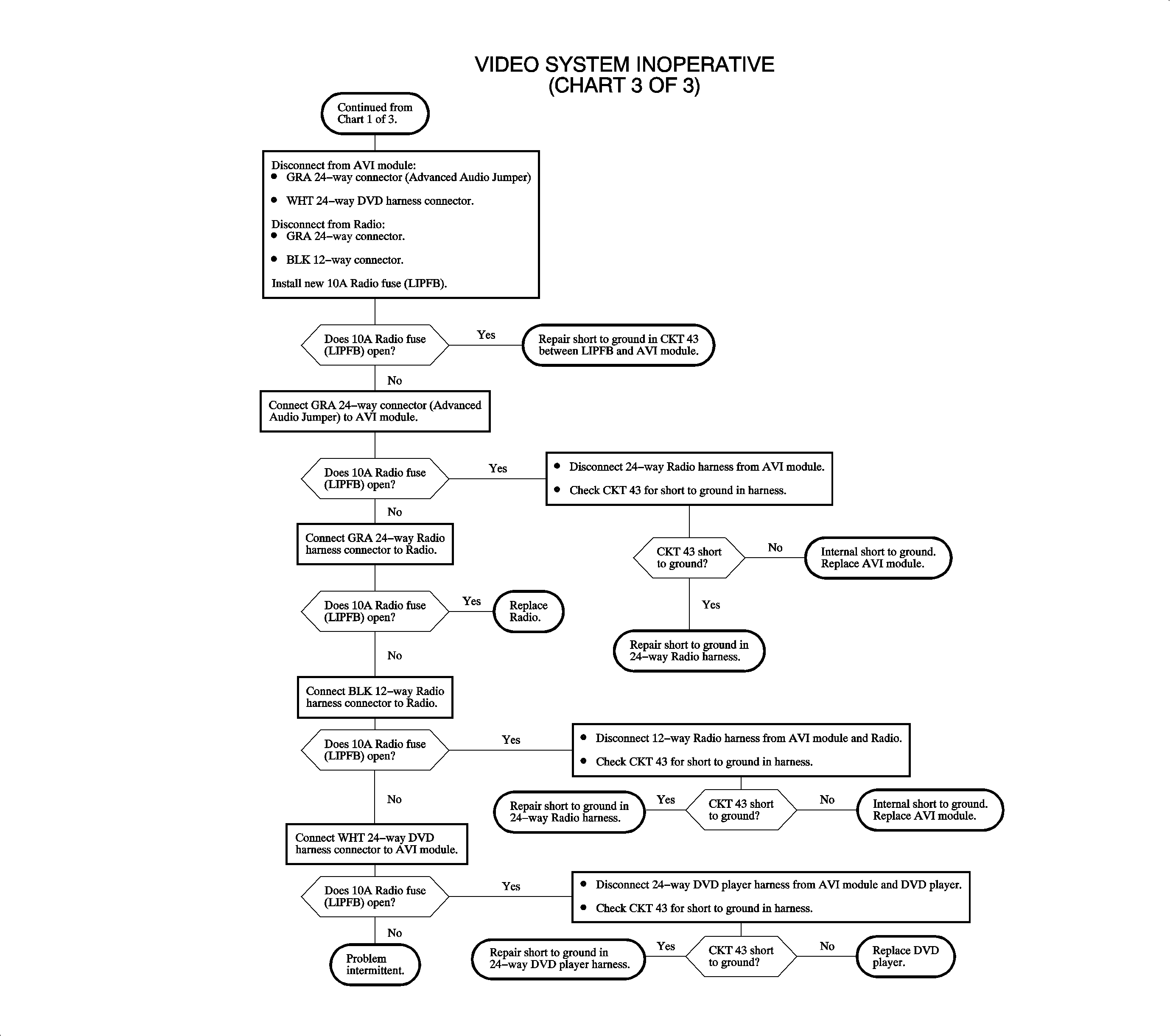
VIDEO DISPLAY INOPERATIVE
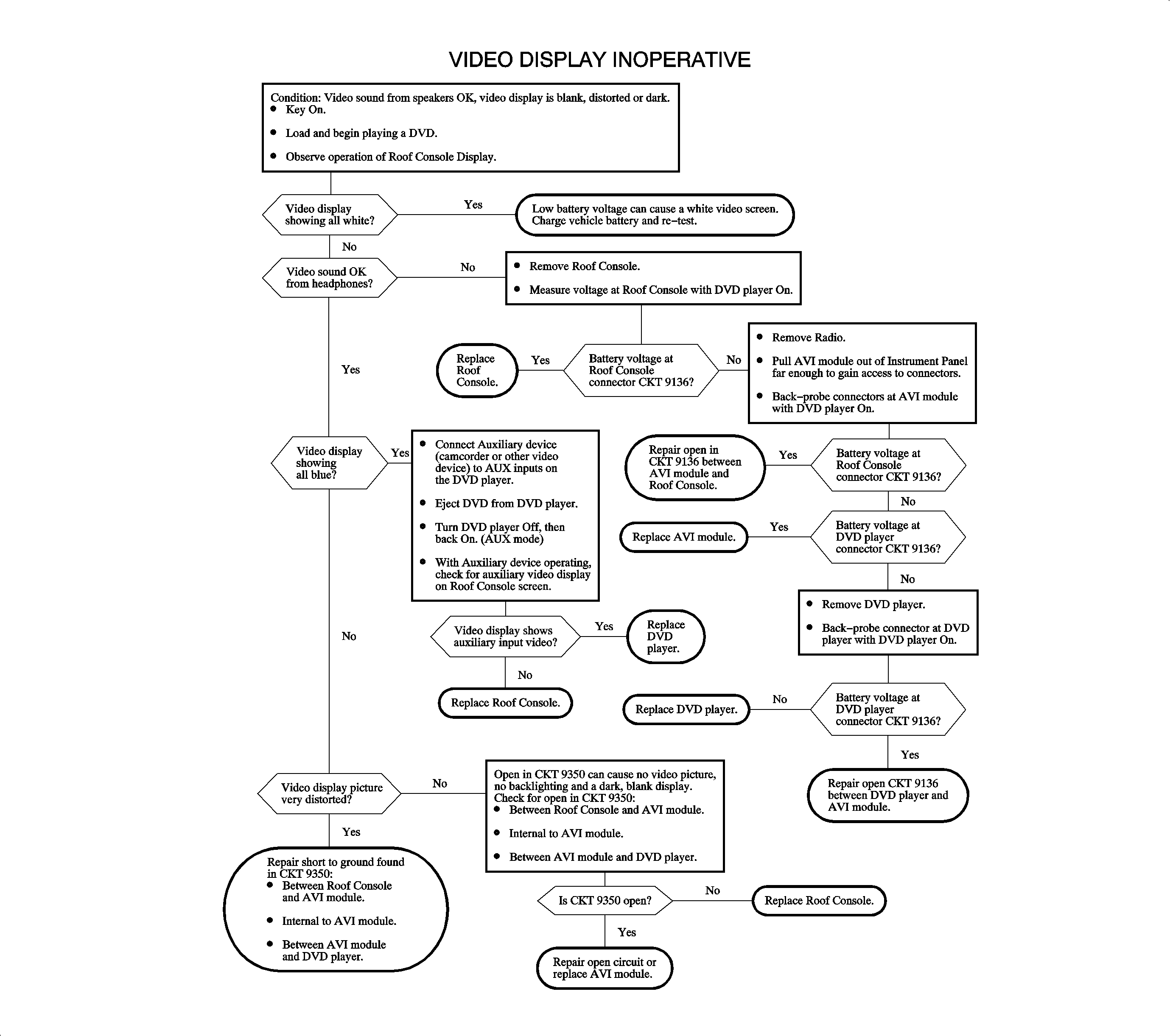
VIDEO AND RADIO SOUND - ONE OR MORE SPEAKERS INOPERATIVE
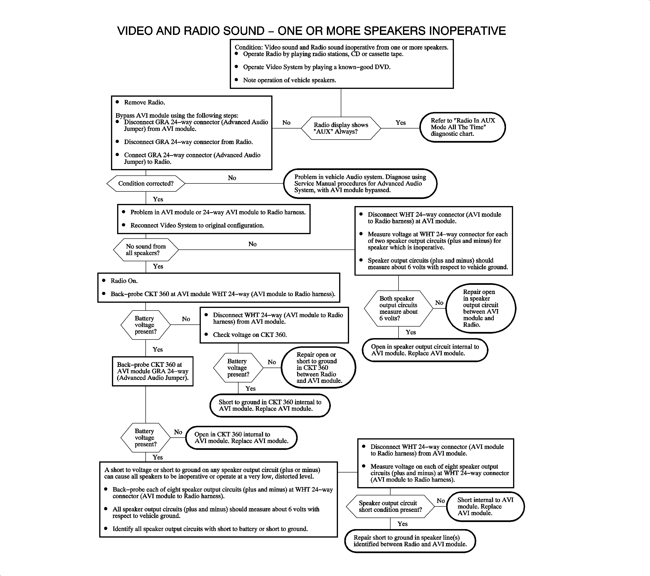
VIDEO SOUND NOT OPERATING CORRECTLY
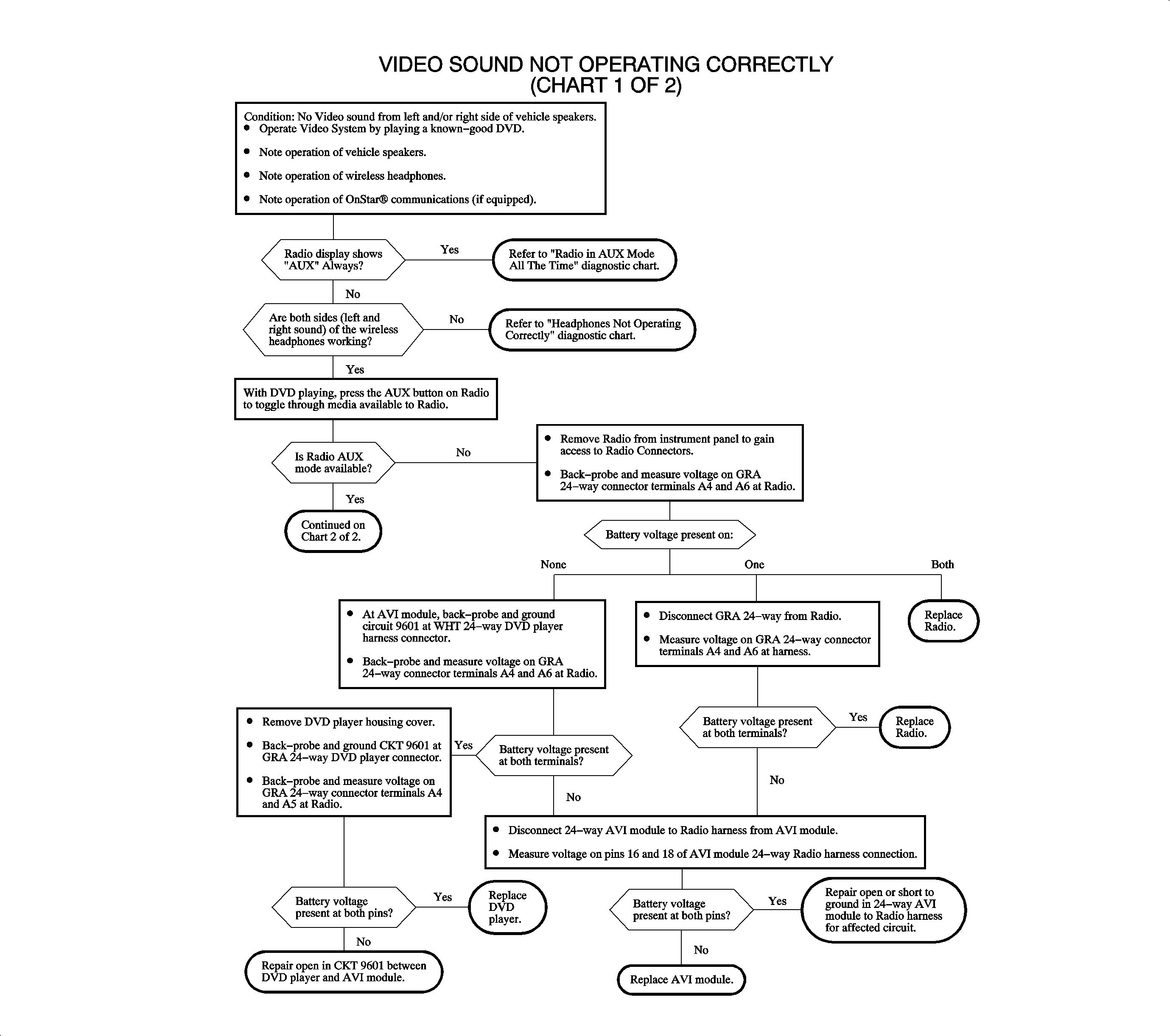
ONSTAR® SOUND NOT OPERATING CORRECTLY
RADIO IN AUX MODE ALL THE TIME
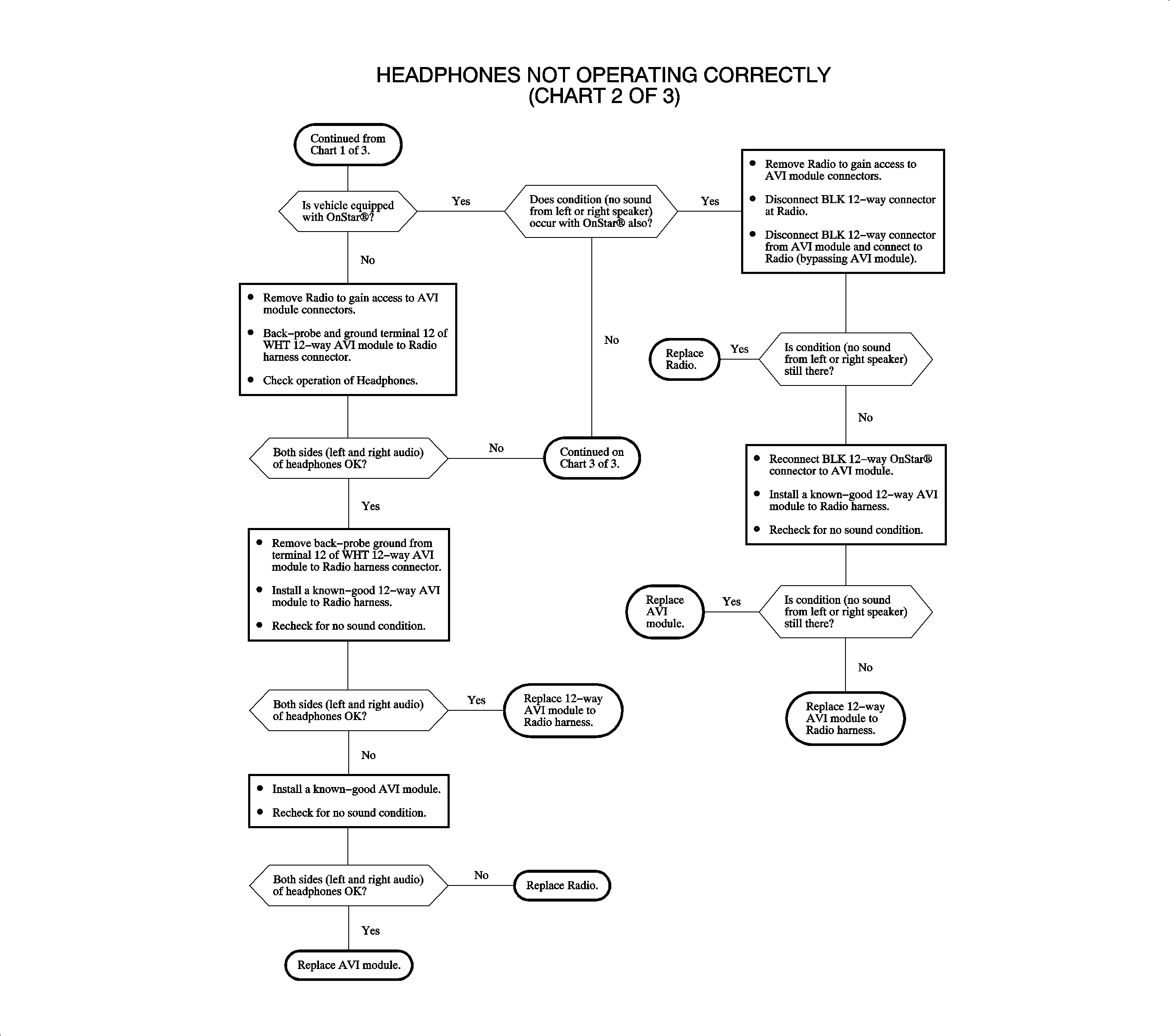
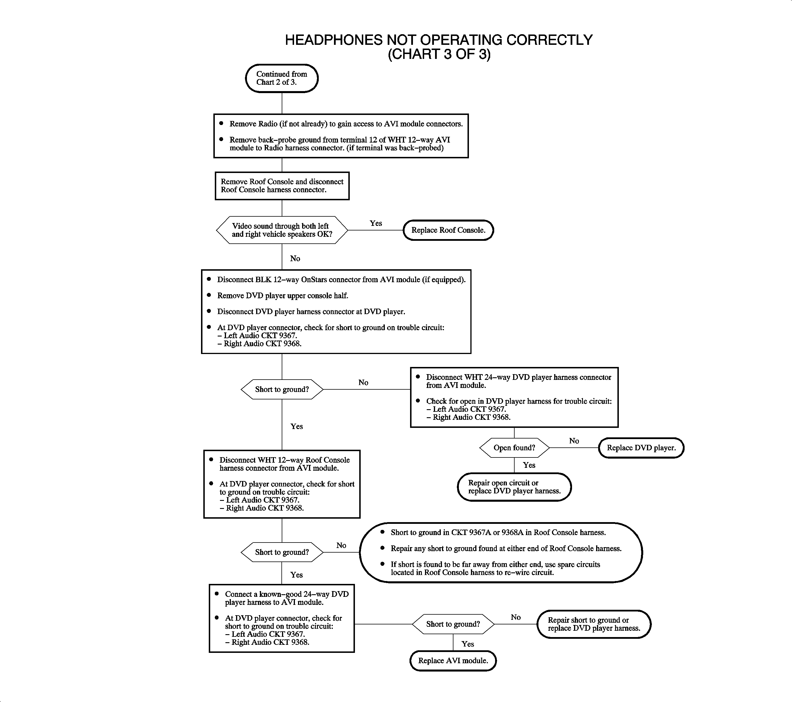
HEADPHONES NOT OPERATING CORRECTLY
REAR SEAT ENTERTAINMENT
DVD PLAYER
The DVD player is designed to be compatible with Digital Video Discs (DVD) authorized for use in the United States and Canada. Regular audio Compact Discs (CD) can also be played by the DVD Player. Home-recorded CDs (CD-R) or home-recorded DVDs may not play in this player.
On power-up, the DVD player is in Auxiliary (AUX) mode. When a DVD begins playing, it switches to DVD mode. Pressing the PWR/AUX or SOURCE button returns the player to AUX mode. Pressing Play from AUX mode puts the player in DVD mode.
Auxiliary input jacks are provided to connect video and audio from other devices. For example, video games or cameras can be connected to use the video display and vehicle speakers. Or, a portable CD or digital media player can be connected to the audio inputs to use the vehicle speakers.
The DVD player sends the video signal to the roof console for video display. Video sound is output to the AVI module where it is sent to the radio for vehicle speaker sound and the roof console for headphone sound.
The DVD player can be controlled by the front panel controls or by the remote control. Remote control commands are transmitted by infrared (IR) signal to the roof console IR transceiver. The roof console IR transceiver sends the IR signal to the DVD player through the wire harness and AVI module.
Power and grounds for the DVD player are the same as the Radio. Connections in the AVI module splice the DVD player power and ground into the radio power and ground. The DVD player provides power to the roof console through the wire harness and AVI module.
ROOF CONSOLE
The roof console houses the video display screen, infrared (IR) transceiver and video/audio electronics. Video signals from the DVD player are processed and displayed on the video display screen. Audio from the DVD player is converted to infrared (IR) output signal to the headphones. only DVD player audio is available through the IR headphones.
IR signals from the remote control are sent by the roof console IR transceiver to the DVD player through the wire harness and AVI module.
The video display screen activates when it is un-latched and pulled down. Pushing up and latching the video display screen turns the screen off, but leaves the audio headphones and remote control features on.
Power and ground to the roof console is provided by the DVD player through the wire harness and AVI module.
RADIO
The radio receives audio input from the entertainment system AVI module. Audio from the DVD player is selectable at the radio like other radio media (CD or Cassette Tape) by pressing the AUX button. The radio makes the video AUX mode available when IGN #2 and IGN #3 are high (battery voltage). In video AUX mode, the radio display shows AUX and fade, balance and tone control are available.
ONSTAR®
If the vehicle is also equipped with OnStar®, DVD audio will be interrupted during an OnStar® call. During an OnStar® call, the mute line is low (ground) and the AVI module relay switches to connect the OnStar® audio to the radio audio inputs. In OnStar® AUX mode, the radio displays AUX and the fade is fixed at full-front, balance control is fixed at center, and the tone control is fixed at a pre-set equalization.
AUDIO VIDEO INTERFACE (AVI) MODULE
The Audio Video Interface (AVI) module connects between the vehicle harness and the radio. The AVI module connects the entertainment system to the audio inputs of the radio and splices the entertainment system power and grounds into the radio power and ground. The AVI module also overrides the video sound input to the radio during an OnStar® call. For the vehicle speaker outputs, amp sense and park lamps input circuits, the AVI Module functions as a junction block, with no other connections to these circuits inside the module.
During DVD player operation, the DVD player audio enable circuit is low (grounded). The AVI module logic turns on the audio relay to connect the DVD audio outputs to the radio audio inputs, and causes IGN #2 and IGN #3 circuits to be high (battery voltage). When IGN #2 and IGN #3 are high, the radio mode switches to video AUX mode.
DVD player audio is interrupted when OnStar® is in use. During an OnStar® call, the OnStar® mute circuit is low and the AVI module logic turns off the audio relay. This disconnects the DVD player audio outputs and connects OnStar® audio outputs to the radio audio inputs. The AVI module turns Off IGN #2 and IGN #3 and the radio switches to OnStar® AUX mode.
HEADPHONES
The wireless headphones receive audio from infrared (IR) signals sent by the roof console IR transceiver. The headphones only receive audio from the DVD player. The radio does not need to be On or in video AUX mode for the headphones to work.
Strong sunlight may interfere with the IR signal and headphone sound operation.
REMOTE CONTROL
The remote control sends infrared (IR) signals to the roof console IR transceiver. These command signals are converted and sent to the DVD player through the wire harness and AVI module.
AUDIO VIDEO INTERFACE (AVI) MODULE
Removal
- Grab center trim plate at A/C vent area and pull gently to disengage attaching clips.
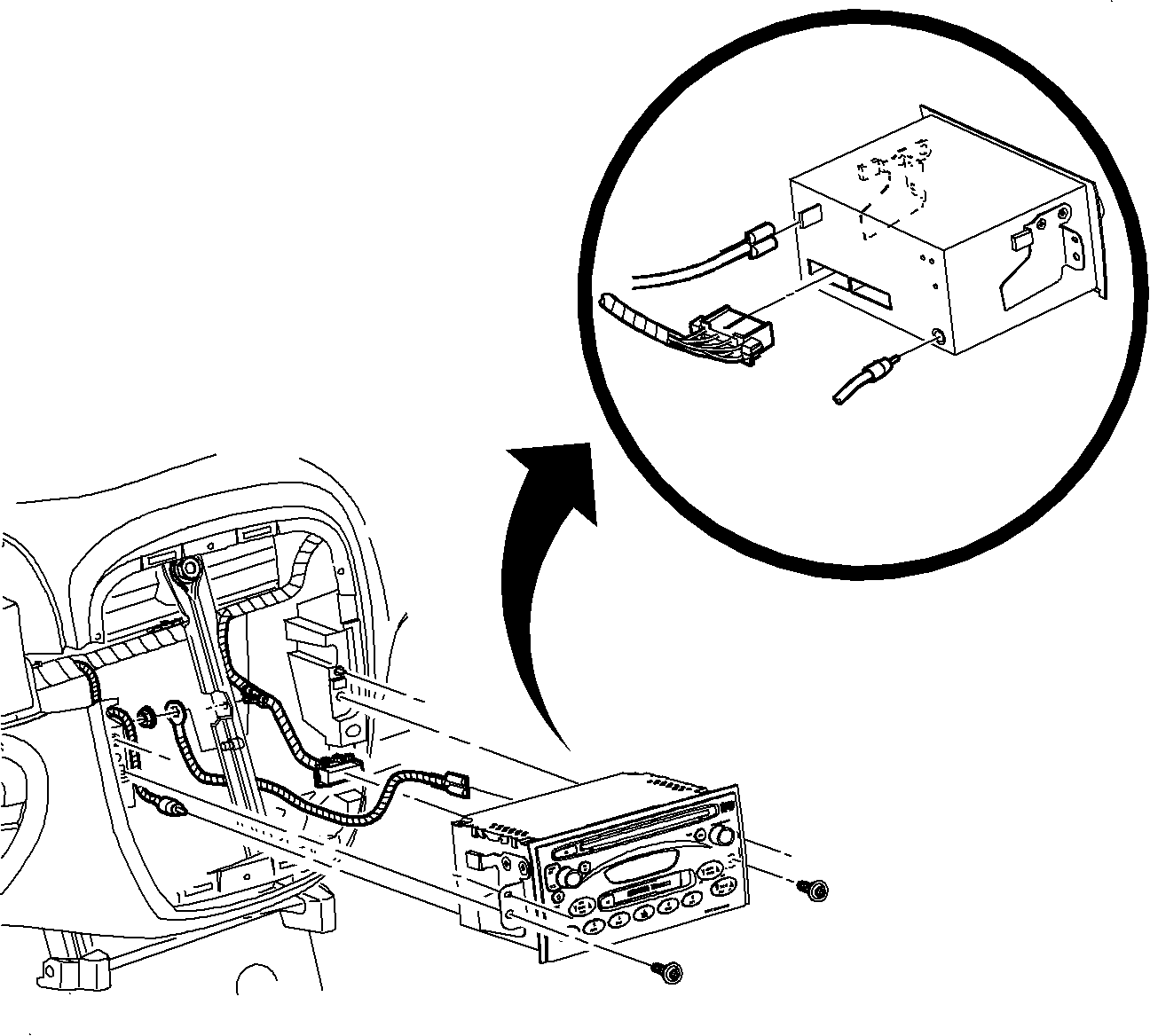
- Remove radio fasteners.
- Pull radio out slightly to access rear of radio.
- Disconnect electrical connector(s), antenna, and radio ground strap spade terminal from rear of radio.
- Remove radio.
- Pull up on AVI module until vehicle harness connectors can be accessed.
- Disconnect vehicle harness connector(s) from AVI module.
- Remove AVI module.
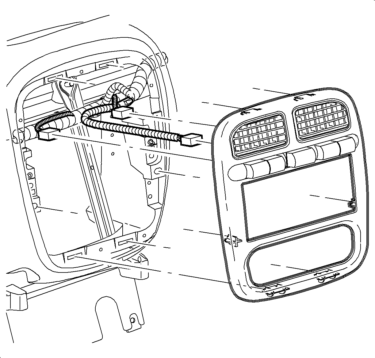
Important: You do not need to disconnect the left heated seat/fog switch, hazard switch, or traction/right heated seat switch electrical connectors.
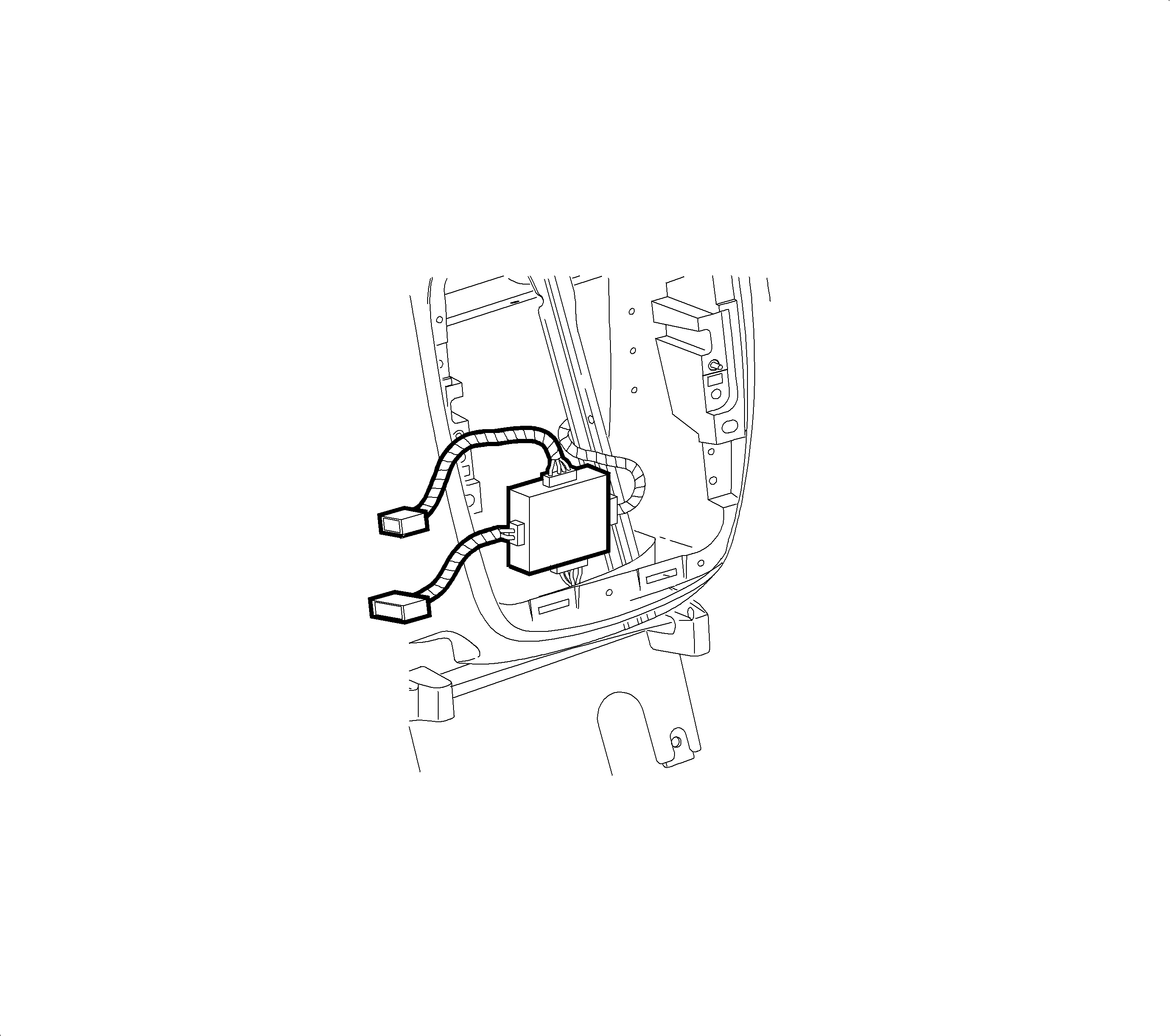
Installation
- Connect vehicle harness connector(s) to the AVI module.
- Position AVI module and push down into place.
- Connect electrical connector(s), antenna, and radio ground strap spade terminal to radio.
- Install radio, making sure all electrical harnesses fit into place without pinching.
- Install radio fasteners.
- Install center trim plate into I/P by gently engaging attachment clips.

Important: If the AVI module is being replaced, transfer the AVI module to radio harnesses (12-way and 24-way) to new AVI module prior to installation.

Tighten
Radio-to-I/P Fasteners: 2.5 N·m (22 in-lbs)

ROOF CONSOLE
Removal
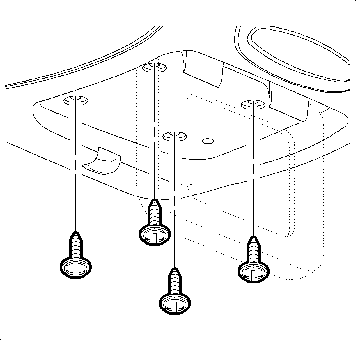
- Lower roof console display screen to access four mounting screws.
- Remove four mounting screws.
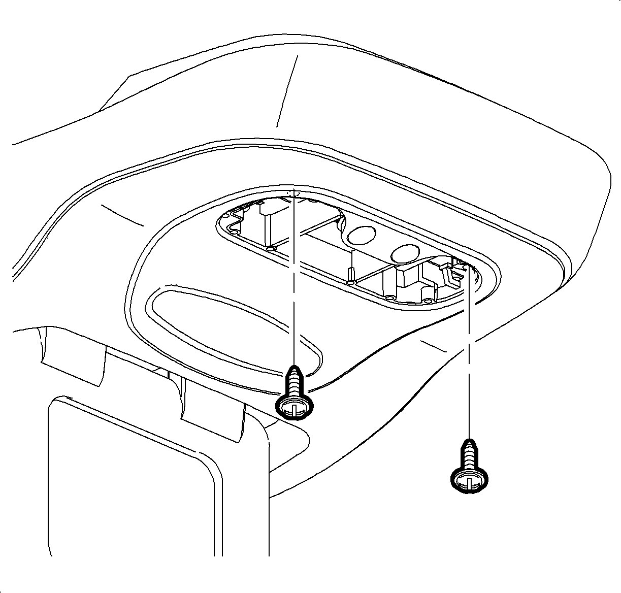
- At left-hand side of dome lamp lens, place small flat head screwdriver into indentation and pry lens loose.
- Remove two screws inside dome lamp.
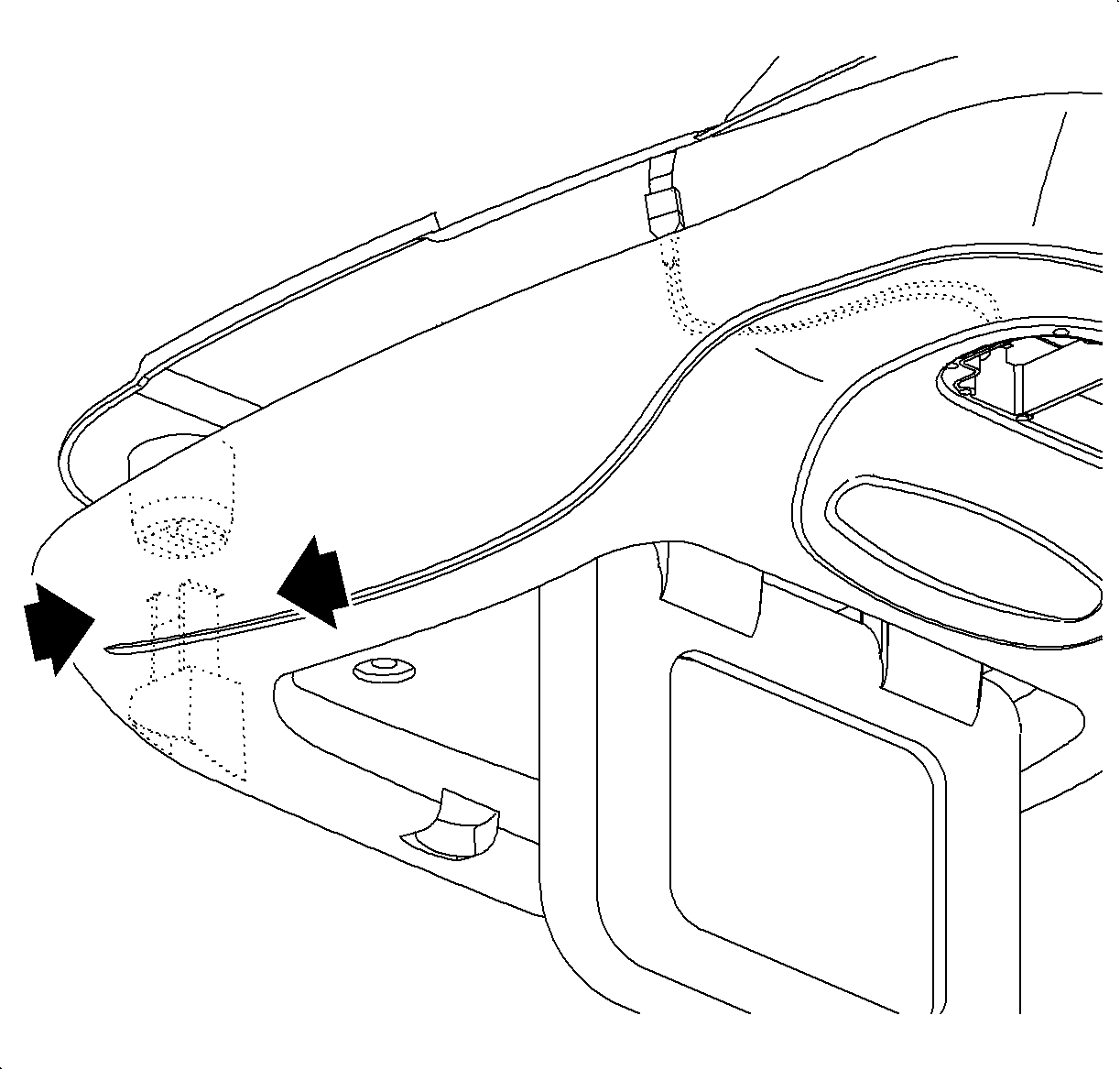
- Gently lower roof console to expose locking tabs located in front left-hand corner.
- Pinch locking tabs together and lower roof console.
- Disconnect dome lamp wire harness at connector.
- Disconnect roof console wire harness from circuit board.
- Remove roof console.
Important: Support rear of roof console while performing next step.
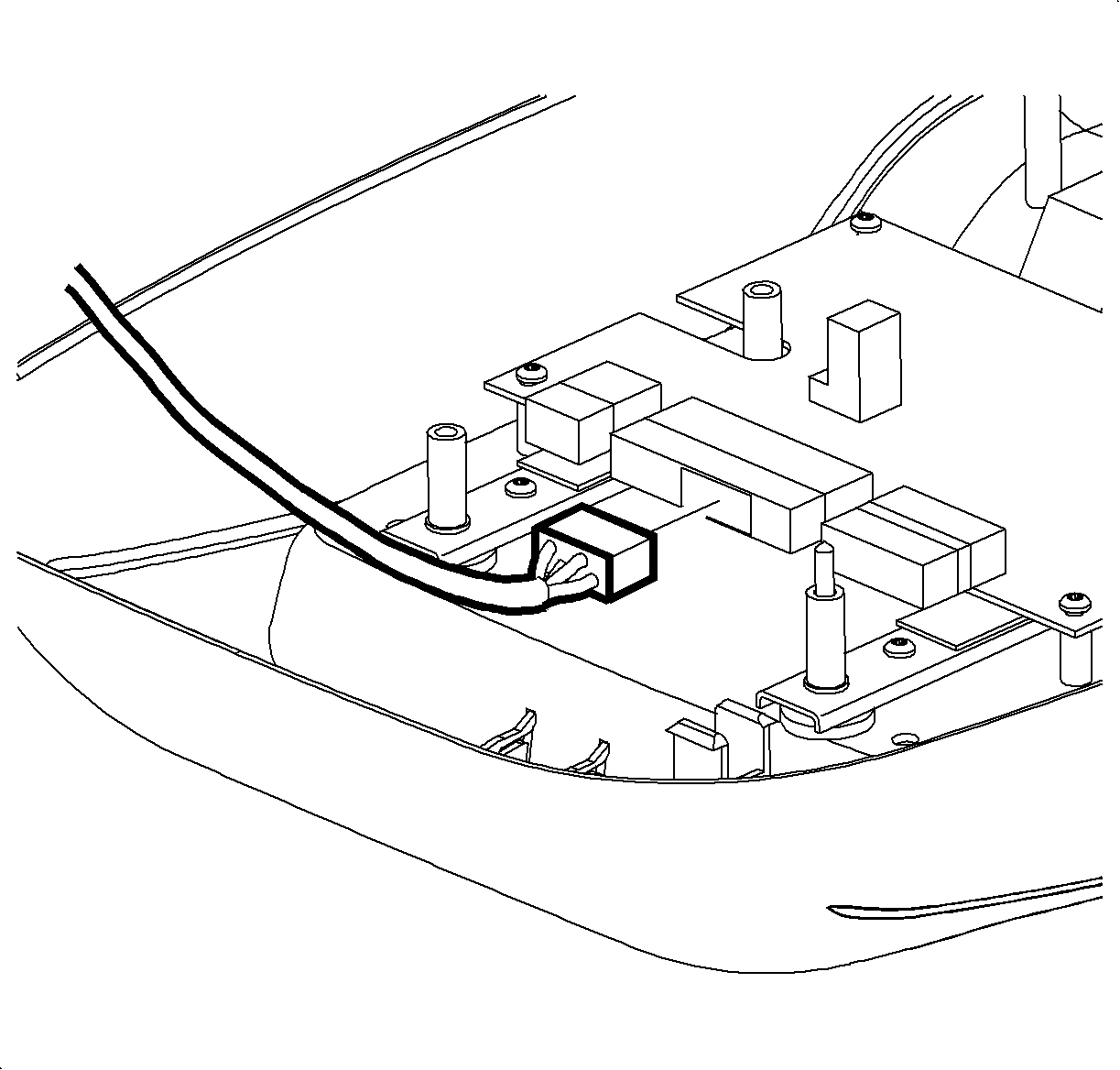
Installation
- Connect roof console wire harness to circuit board.
- Connect dome lamp wire harness.
- Line-up roof console locking tabs with roof bracket.
- Push-up on roof console to engage locking tabs.
- Support rear of roof console.
- Install two screws inside dome lamp.
- Snap dome lamp lens into place.
- Install four screws above roof console display.


Tighten
Roof Console to Bracket: 2.0 N·m (18 in-lbs)

Tighten
Roof Console to Bracket: 2.0 N·m (18 in-lbs)
ROOF CONSOLE DISPLAY LATCH
Removal
- Remove roof console.
- Push-down on two locking tabs on the latch.
- Push latch rearward and un-hook spring.
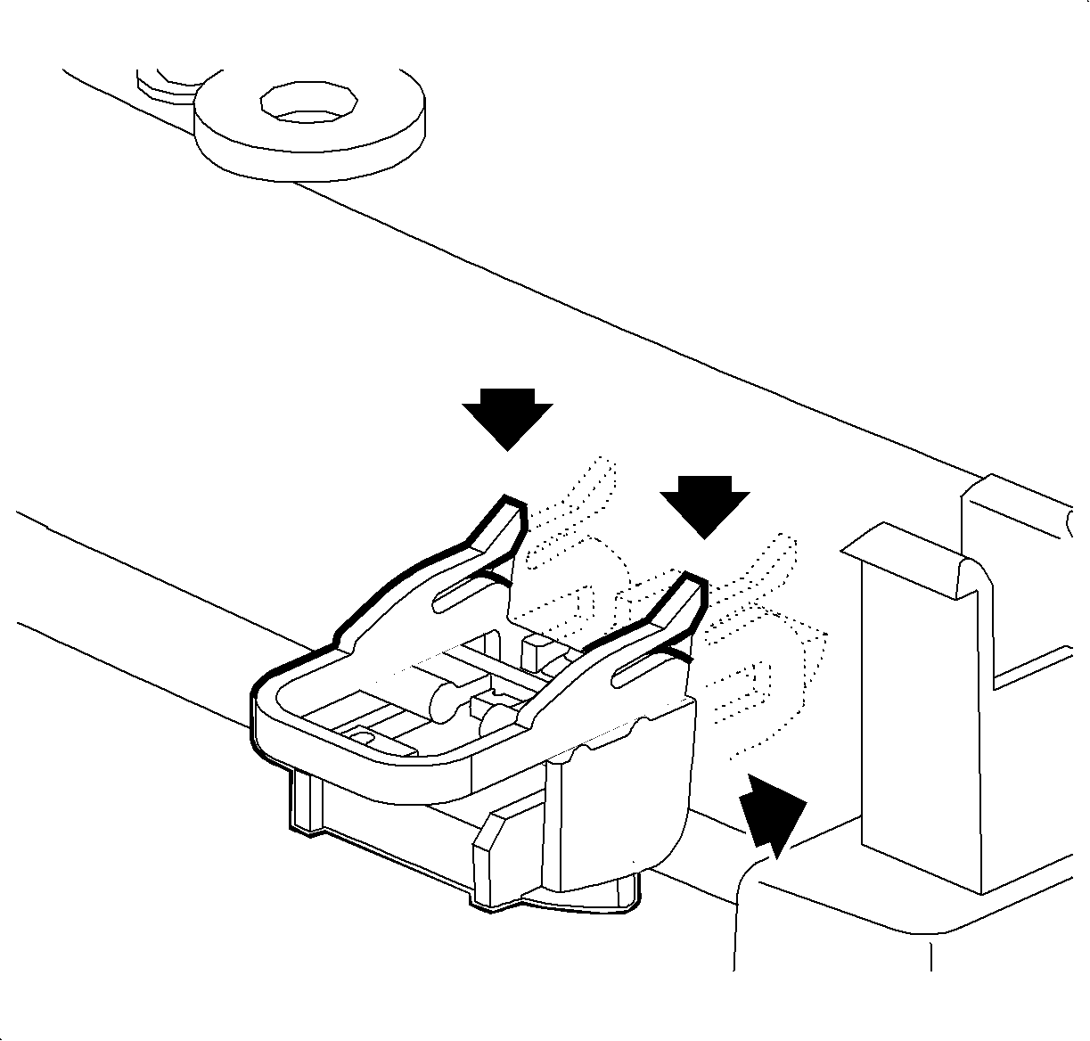
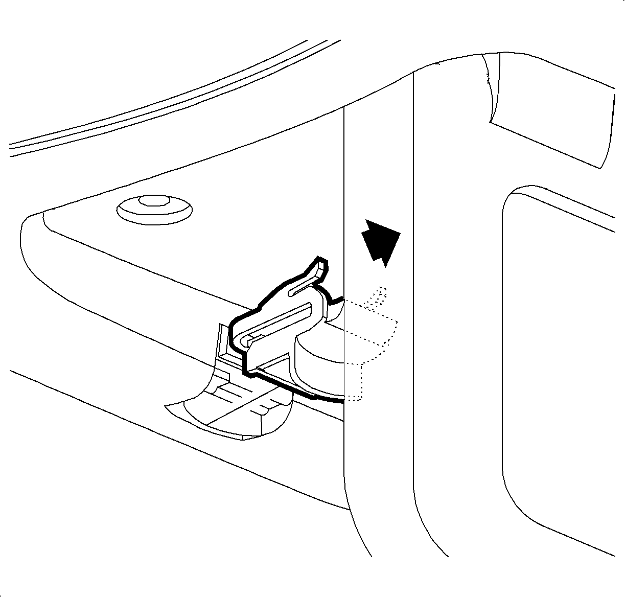
Installation
- Align latch and spring into latch opening.
- Hook spring onto roof console housing.
- Push latch into roof console housing until locking tabs engage.
- Install roof console.

ROOF CONSOLE HEADLINER REPLACEMENT
- Remove roof console.
- Partially remove headliner to allow access to the roof console wiring harness. Refer to "Headliner" removal procedure in the Body Electrical Service Manual.
- Remove roof console wiring harness from headliner by cutting through the retaining glue.
- Remove headliner from vehicle.
- Cut through the glue retaining the dome lamp harness and place out of the way.
- Place new headliner on a flat surface with the fabric side up.
- Place old headliner on new headliner and align together, using front visor holes and rear high mount stop lamp cutouts as alignment reference points.
- Using the old headliner as a template, mark a pencil line 1/4 inch inside the roof console opening on the new headliner.
- Using a sharp utility knife, cut along the pencil line on the fabric side of the new headliner.
- Partially install headliner into vehicle, placing the front edge of the headliner first.
- Locate roof console wire harness next to headliner wiring harness.
- Secure roof console wiring harness to headliner with retaining tape.
- Install headliner to roof.
- Finish installing headliner. Refer to "Headliner" installation procedure in the Body Electrical Service Manual.
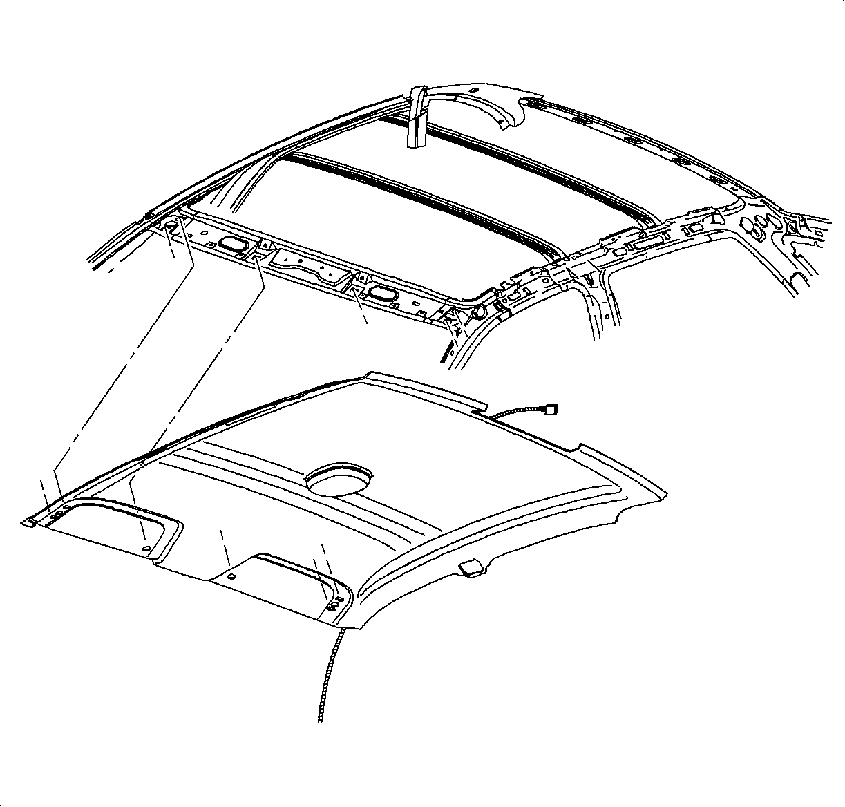
Important: New replacement headliners must be modified prior to installation on vehicles equipped with the optional rear seat entertainment system. Use the following procedure to make needed modifications when replacing a headliner.
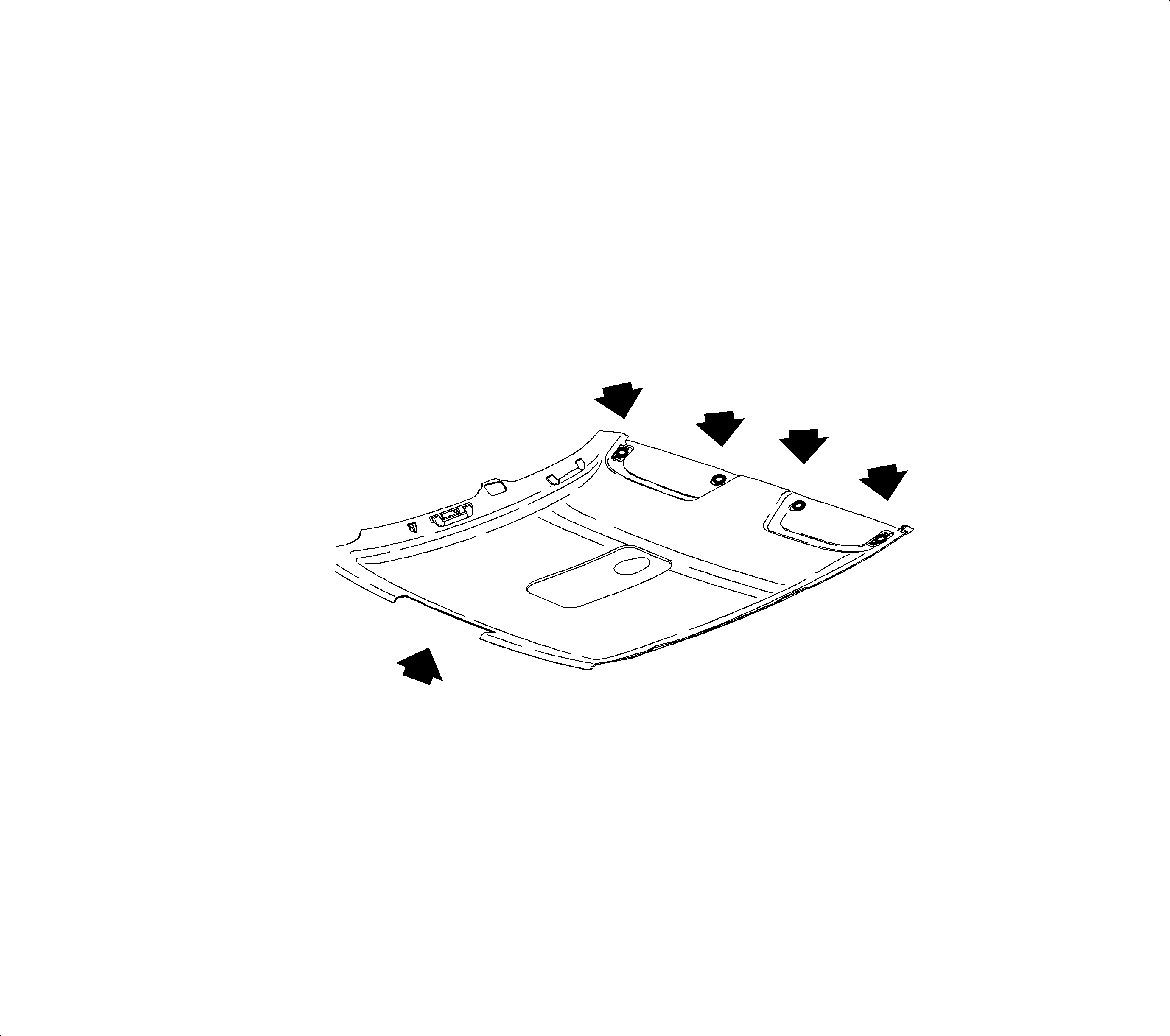
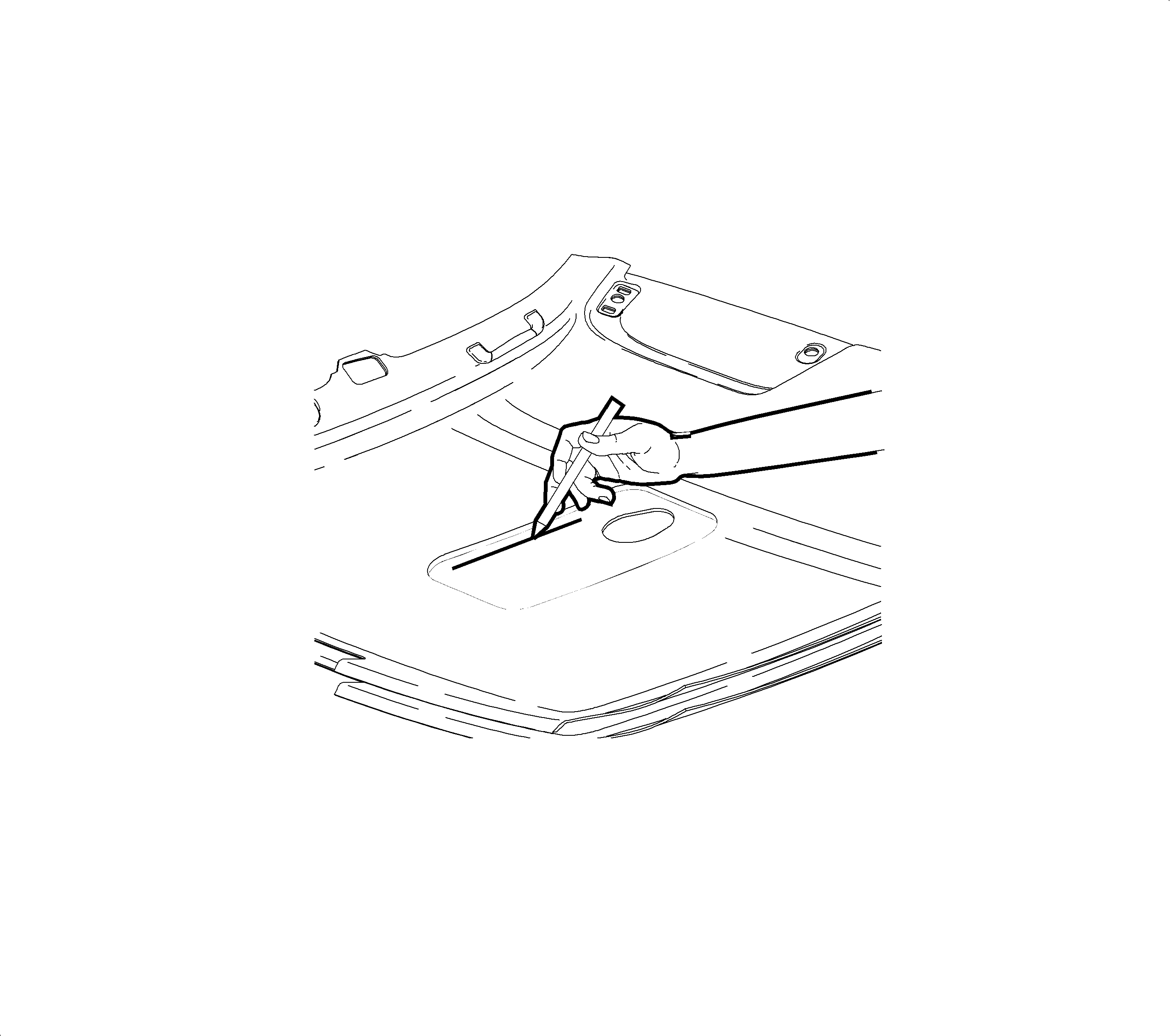
Important: Markers may bleed into fabric and therefore are not recommended.
Important: Fabric may tear if cut from the fiberglass side of the new headliner.
Important: Be sure that all wires on the back of the headliner are out of the way before cutting.

Important: Trim headliner opening if headliner material interferes with roof console bracket.
DVD PLAYER
Removal
- Remove two screws from the rear underside of DVD player console upper cover.
- Slide upper cover to the rear and lift-up to remove.
- Remove bracket to DVD player screw on the left side.
- Remove bracket to lower console screw on right side.
- Remove nut at rear of DVD player.
- Lift up DVD player and disconnect wiring harness and ground strap.
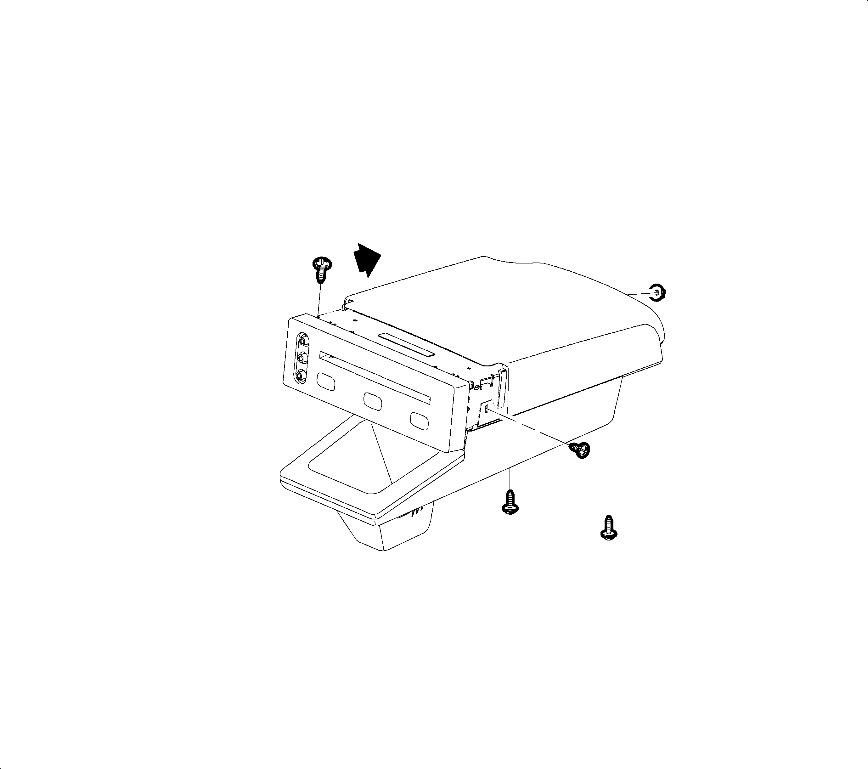
Important: A Torx T8 or T10 driver is required to remove the DVD player. For 2002 L-Series vehicles with a VIN up to and including 1G8JS54F12Y576087, use a T8 driver. For 2002 L-Series vehicles with a VIN break of 1G8JS54F12Y576088 or higher, use a T10 driver. For 2003 L-Series vehicles, use a T10 driver.
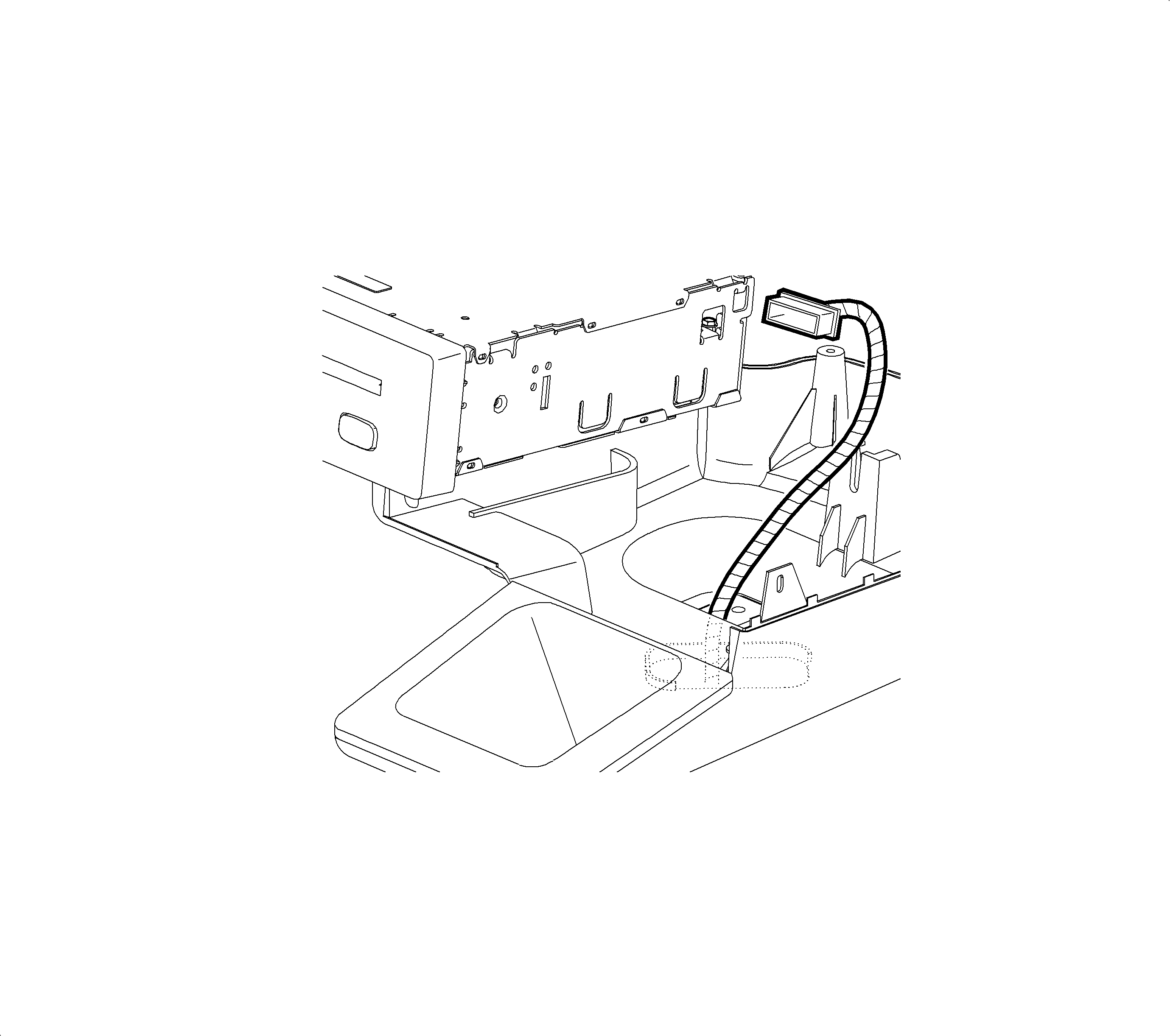
Installation
- Connect DVD player wiring harness and ground strap.
- Align a stud at rear of DVD player to the slot in the lower console.
- Install bracket to lower console screw on right side.
- Install bracket to DVD player screw on the left side.
- Install nut at rear of DVD player.
- Position console upper cover slightly rearward of the DVD player faceplate.
- Slide console upper cover forward into DVD player faceplate.
- Install screws into rear underside of center console.

Important: If the DVD player is being replaced, transfer the right-side bracket from the old player to the replacement player prior to installation.
Tighten
Right Bracket to DVD Player: 1 N·m
(9 in-lbs)

Tighten
Right Bracket to Lower Console: 1 N·m
(9 in-lbs)
Tighten
Left Bracket to DVD Player: 1 N·m (9 in-lbs)
Tighten
DVD Player Nut: 1 N·m (9 in-lbs)
Tighten
Center Console Upper Cover Screw: 1 N·m
(9 in-lbs)
DVD PLAYER LOWER CENTER CONSOLE
Removal
- Remove DVD player.
- Remove screw at bottom of storage bin under rubber pad.
- Remove two screws in rear of lower center console.
- Remove lower console, feeding DVD player wiring harness through opening.
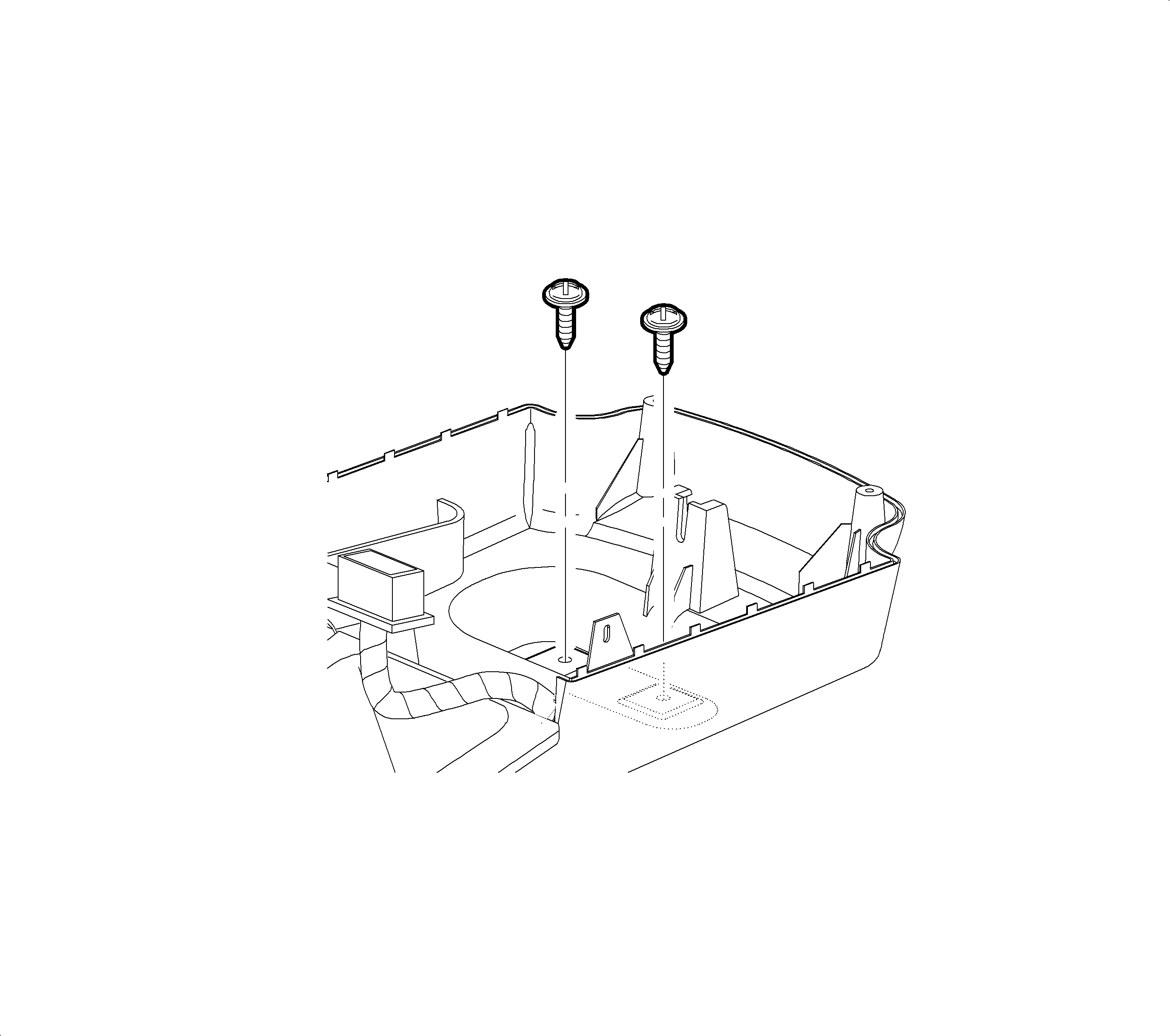
Installation
- Position DVD player lower console into the console, feeding DVD player harness through the opening.
- Install two screws in the rear of the lower center console.
- Install screw into bottom of storage bin.
- Install DVD player.

Tighten
DVD Player Lower Console Screw: 2.5 N·m
(22 in-lbs)
Tighten
DVD Player Lower Console Screw: 2.5 N·m
(22 in-lbs)
Parts Information
Part Number | Description |
|---|---|
22693802 | PLAYER ASM - VIDEO DISC (1st & 2nd Design) |
22693770 | CONTROL ASM - VIDEO T/PLYR REM (1st & 2nd Design) |
22694087 | MODULE KIT - AUDIO/VIDEO INTERFACE (1st Design) |
22706131 | MODULE KIT - AUDIO/VIDEO INTERFACE (2nd Design) |
Important: 2002 model year vehicles with Rear Seat Entertainment utilize 1st design AVI module and 1st or 2nd design DVD Player and Remote control. 2003 model year vehicles with Rear Seat Entertainment without OnStar® utilize 1st design AVI Module and 2nd design DVD Player and Remote control. 2003 model year vehicles with Rear Seat Entertainment and OnStar® utilize 2nd design parts throughout.
Important: Second design parts are compatible with vehicles built with 1st design components and should be used for replacement parts when servicing 1st design systems.
