Exhaust Manifold Replacement In Vehicle - L61
Removal Procedure
- Raise the vehicle on a hoist.
- Remove the exhaust manifold pipe-to-exhaust manifold nuts. Automatic shown, manual similar.
- Pull down on the exhaust manifold pipe just enough to free from the manifold studs and secure to the frame.
- Lower the vehicle.
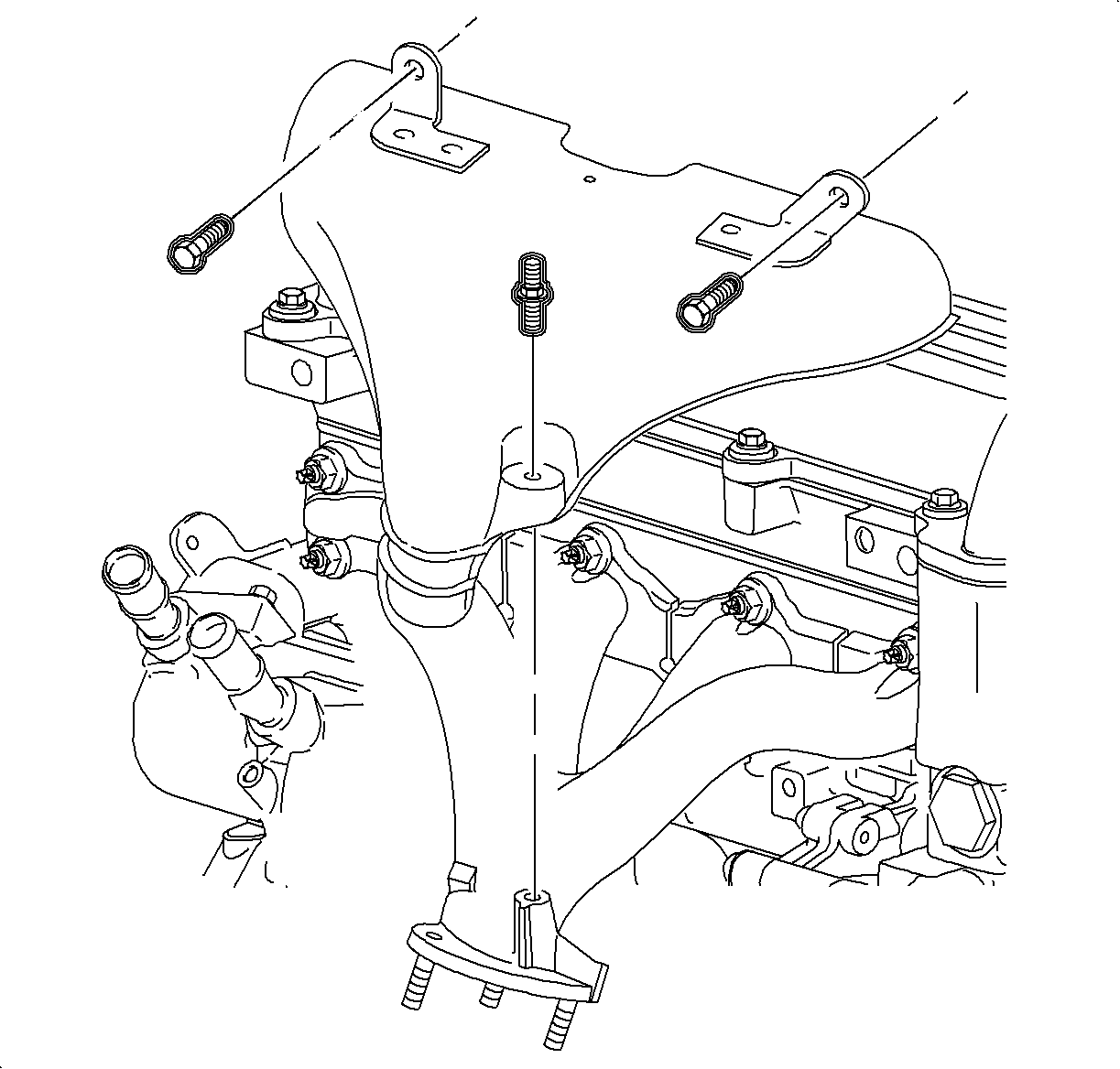
- Remove the exhaust manifold heat shield.
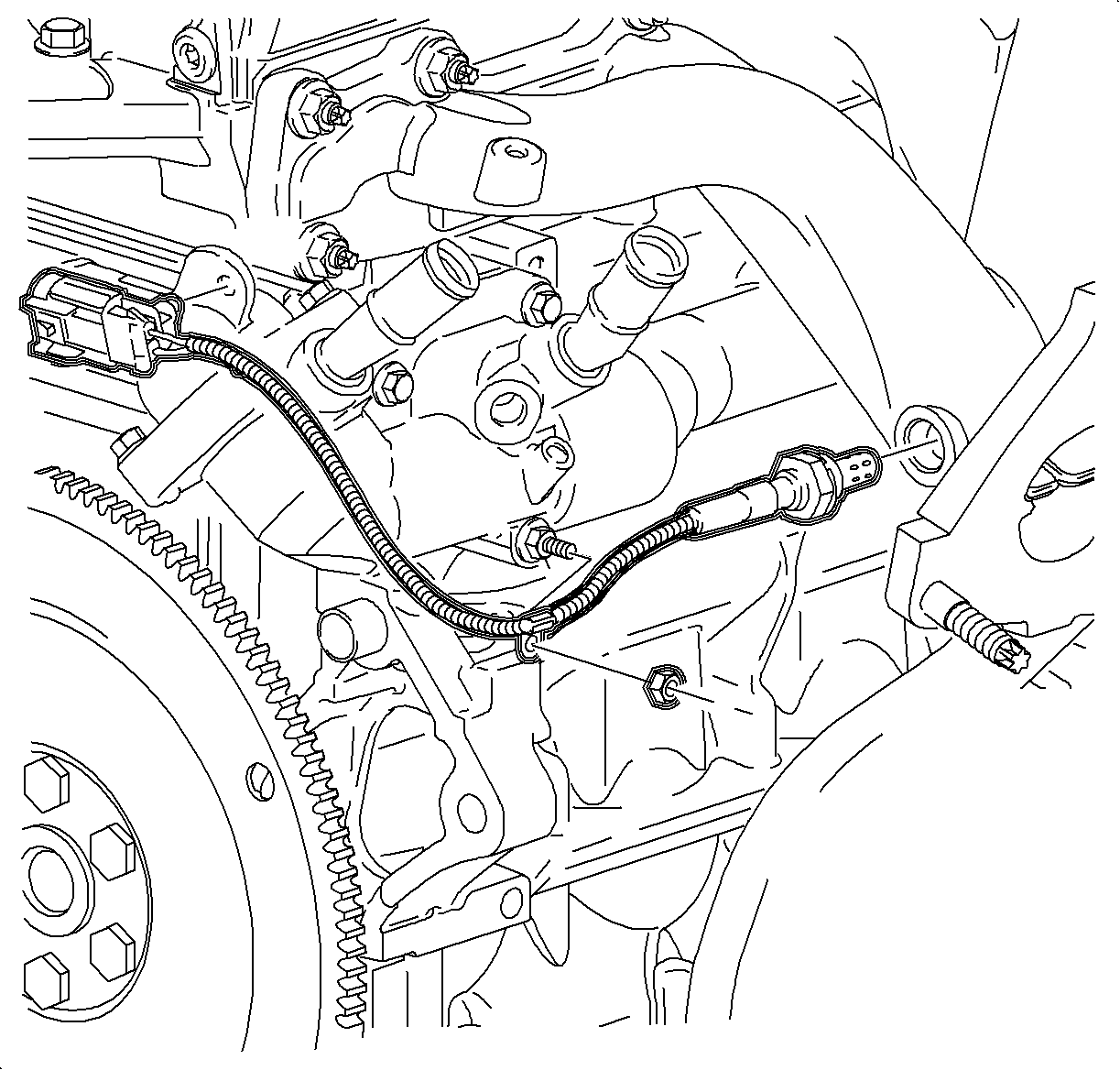
- Disconnect the exhaust manifold heated oxygen sensor electrical connection.
- Remove the heated oxygen sensor from the manifold.
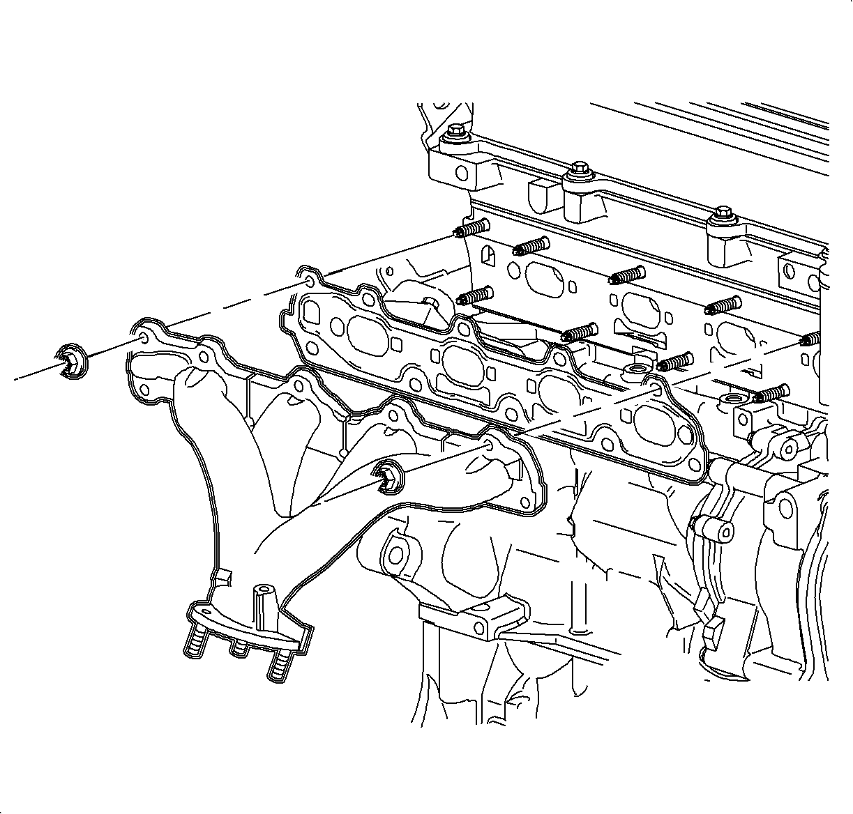
- Remove the exhaust manifold nuts.
- Remove the exhaust manifold and discard the gasket.
Caution: Refer to Vehicle Lifting Caution in the Preface section.
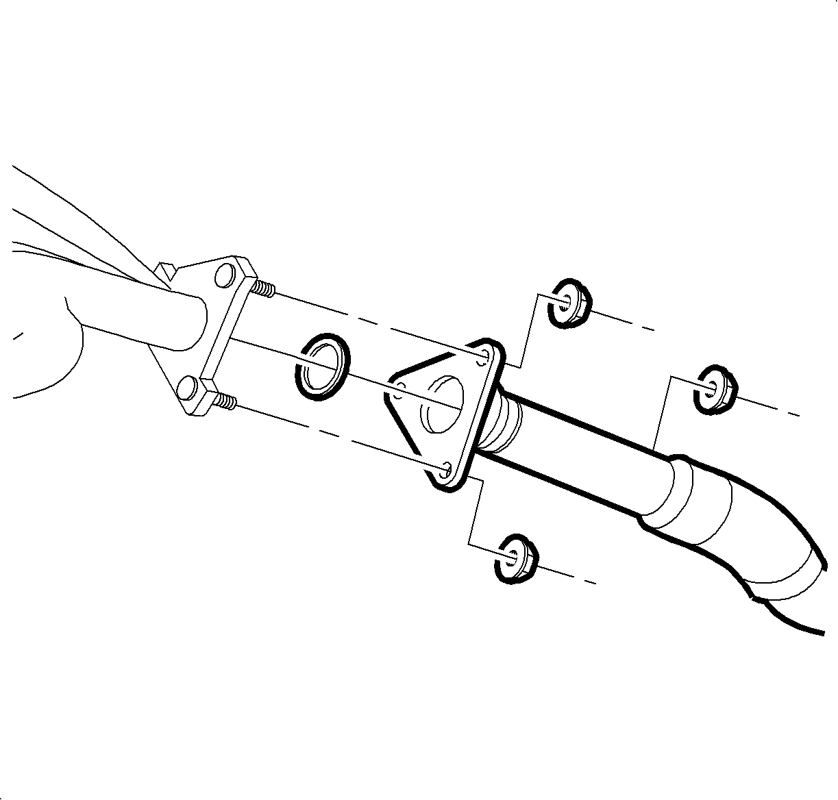
Notice: Avoid excessive movement of the pipe.
Installation Procedure
- Install the new exhaust manifold gasket on the cylinder head.
- Install the exhaust manifold.
- Install the exhaust manifold nuts.
- Install the heated oxygen sensor.
- Connect the exhaust manifold heated oxygen sensor electrical connection.
- Install the exhaust manifold heat shield.
- Install the new exhaust manifold flange gasket onto the exhaust manifold flange studs.
- Raise the vehicle on a hoist.
- Position the exhaust manifold pipe flange onto the exhaust manifold studs.
- Lower the vehicle.
- Start the vehicle and inspect for leaks.

Tighten
Tighten the exhaust manifold-to-cylinder head nuts
to 18 N·m (13 lb ft).

Tighten
Tighten the oxygen sensor-to-exhaust manifold pipe
to 45 N·m (33 lb ft).

Tighten
Tighten the exhaust manifold heat shield bolts to
25 N·m (18 lb ft).

Tighten
Tighten the exhaust manifold pipe-to-exhaust manifold
nuts to 30 N·m (22 lb ft).
Exhaust Manifold Replacement Rear - L81
Tools Required
J 39194-C Oxygen Sensor Wrench
Removal Procedure
- Disconnect the exhaust manifold heated oxygen sensor electrical connection.
- Remove the exhaust manifold heated oxygen sensor using the J 39194-C .
- Remove the EGR pipe.
- Disconnect the rear exhaust manifold pipe heated oxygen sensor electrical connection.
- Remove the rear exhaust manifold pipe heat shield.
- Remove the rear exhaust manifold pipe heated oxygen sensor.
- Raise the vehicle on a hoist.
- Remove the rear exhaust manifold pipe to front exhaust manifold pipe attachment bolts.
- Remove the rear exhaust manifold pipe to resonator bolts.
- Remove the rear exhaust manifold pipe assembly from the vehicle.
- Remove the exhaust manifold nuts.
- Remove the exhaust manifold and gasket.
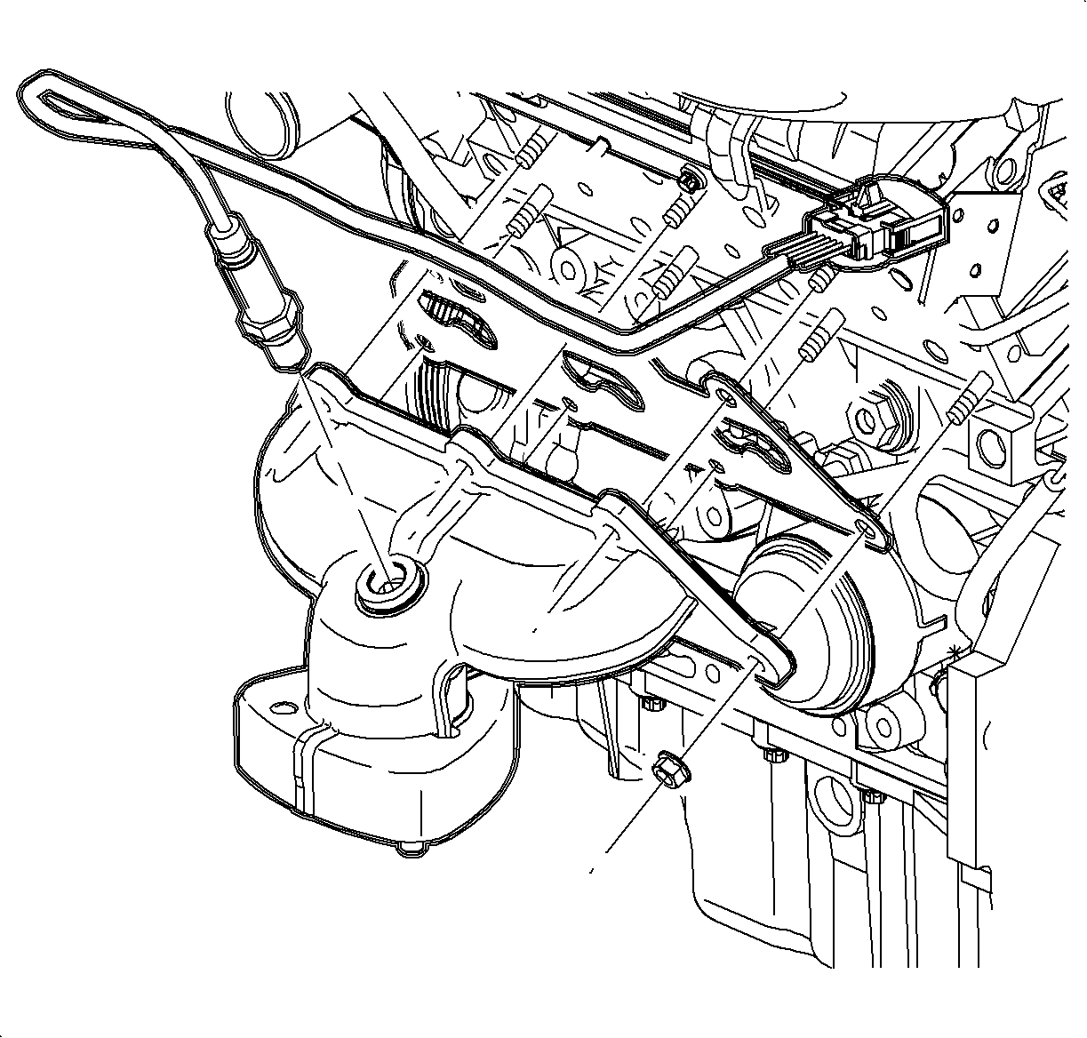
Important: Do not apply grease or silicon products to the heated oxygen sensor (H02S-2). Do not alter the wiring in any way. The wires carry air reference to the sensor.
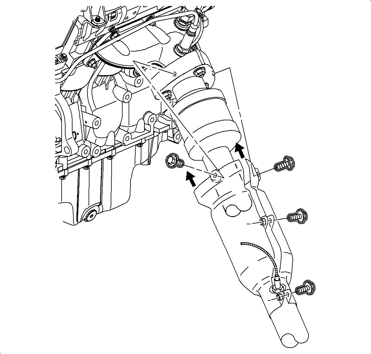
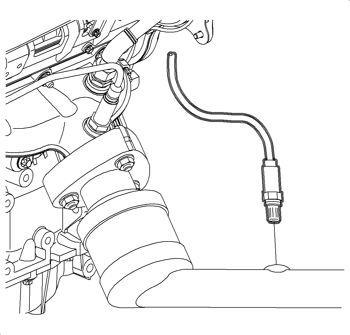
Caution: Refer to Vehicle Lifting Caution in the Preface section.
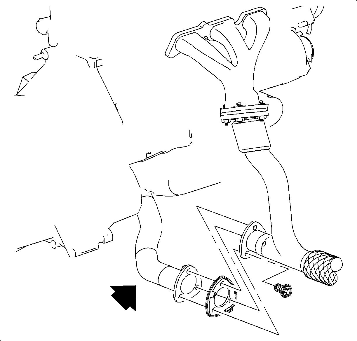
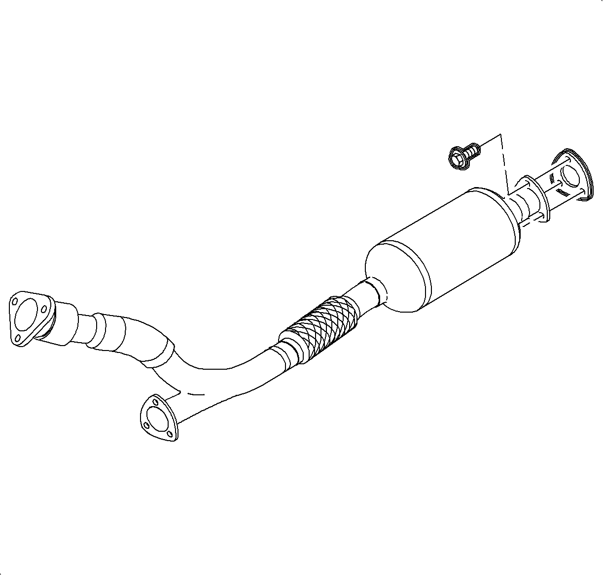
Installation Procedure
- Install the exhaust manifold and the new gasket.
- Install the exhaust manifold nuts.
- Install the rear exhaust manifold pipe assembly and gaskets.
- Install the exhaust manifold to rear exhaust manifold pipe nuts.
- Install the front exhaust manifold pipe to rear exhaust manifold pipe attachment bolts.
- Install the rear exhaust manifold pipe to resonator bolts.
- Tighten the rear exhaust manifold pipe to exhaust manifold nuts.
- Lower the vehicle.
- Install the EGR pipe to the exhaust manifold and EGR flange.
- Install the heated oxygen sensor using the J 39194-C .
- Connect the rear exhaust manifold pipe heated oxygen sensor electrical connections.
- Install the exhaust manifold pipe heat shield.
- Start the vehicle and inspect for exhaust leaks.
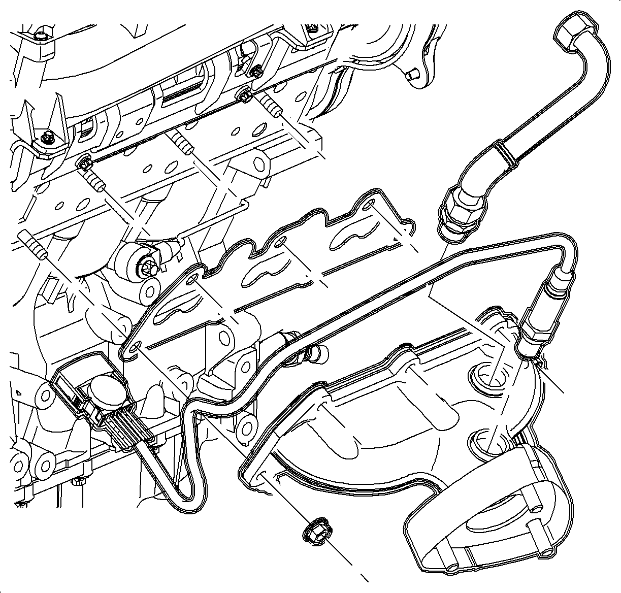
Tighten
Tighten the exhaust manifold nut to 20 N·m
(15 lb ft).
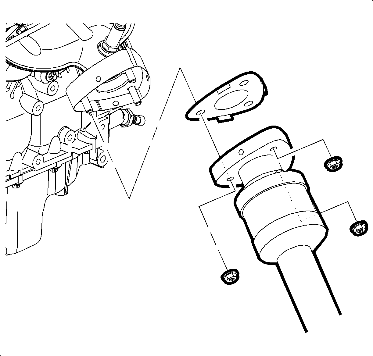
Important: Do not tighten the fasteners.

Tighten
Tighten the exhaust manifold pipe bolts to 20 N·m
(15 lb ft).

Tighten
Tighten the exhaust manifold pipe bolts to 20 N·m
(15 lb ft).

Tighten
Tighten the exhaust manifold pipe-to-exhaust manifold
nuts to 30 N·m (25 lb ft).
Tighten
Tighten the EGR pipe bolts to 25 N·m
(18 lb ft).
Notice: Refer to Heated Oxygen Sensor Damage Notice in the Preface section.

Tighten
Tighten the oxygen sensors (exhaust manifold) to
50 N·m (37 lb ft).

Tighten
Tighten the exhaust manifold pipe heat shield bolts
to 8 N·m (71 lb in).
Exhaust Manifold Replacement Front - L81
Tools Required
| • | J 39194-C Oxygen Sensor Wrench |
| • | SA9105E Engine Support Fixture (3 Bar) |
Removal Procedure
- Disconnect the exhaust manifold heated oxygen sensor (HO2S) electrical connection.
- Remove the exhaust manifold HO2S using the J 39194-C .
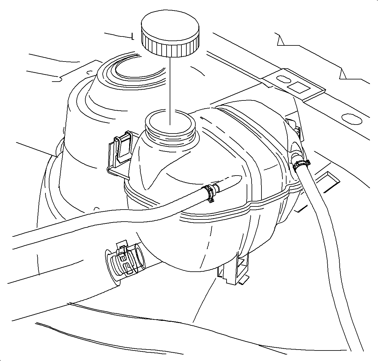
- Drain the coolant. Refer to Cooling System Draining and Filling in Engine Cooling.
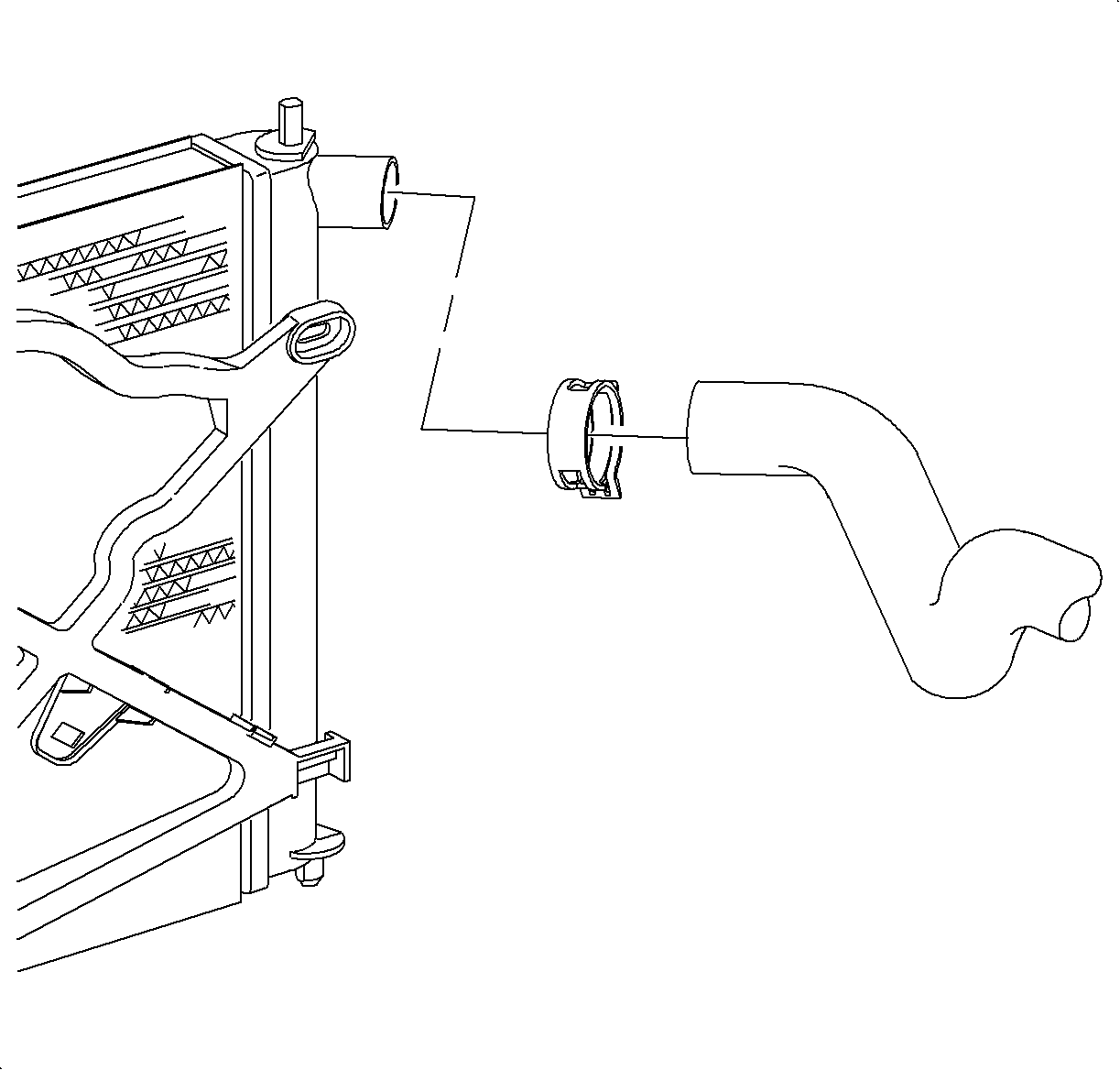
- Remove the upper radiator hose from the coolant extension housing.
- Install the SA9105E and support the powertrain.
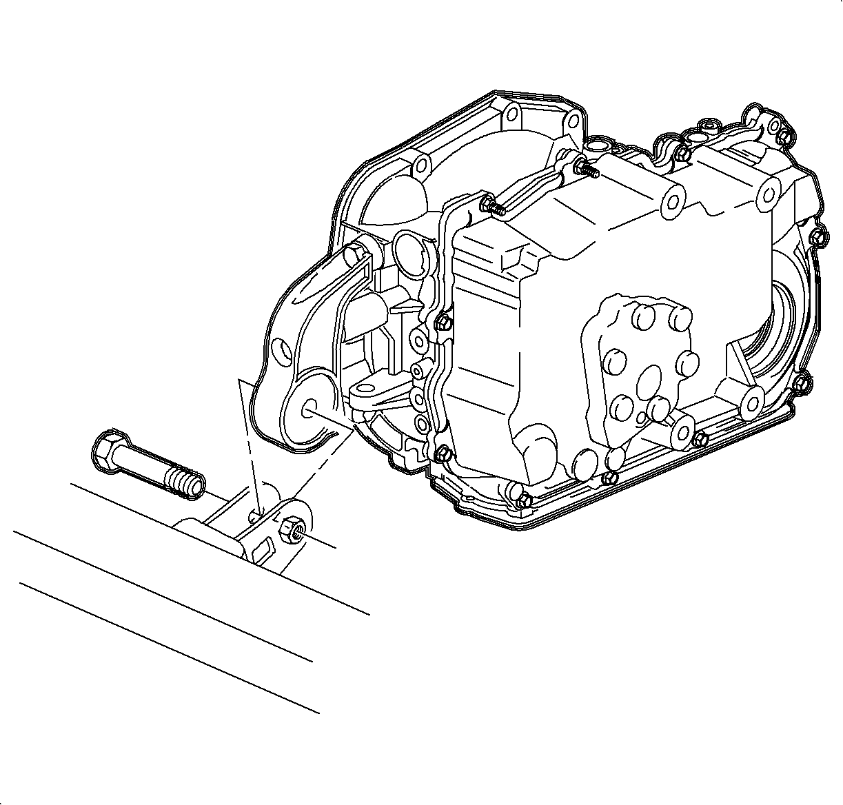
- Remove the front transaxle mount through bolt.
- Raise the powertrain with the engine support fixture to provide clearance to pull the extension housing above the coolant module.
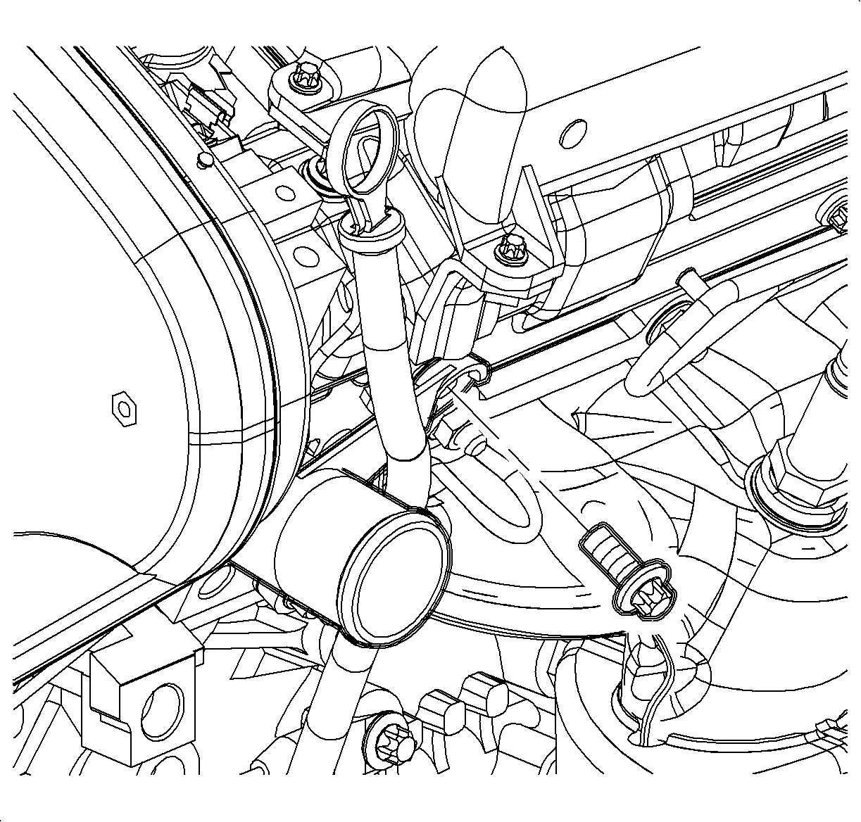
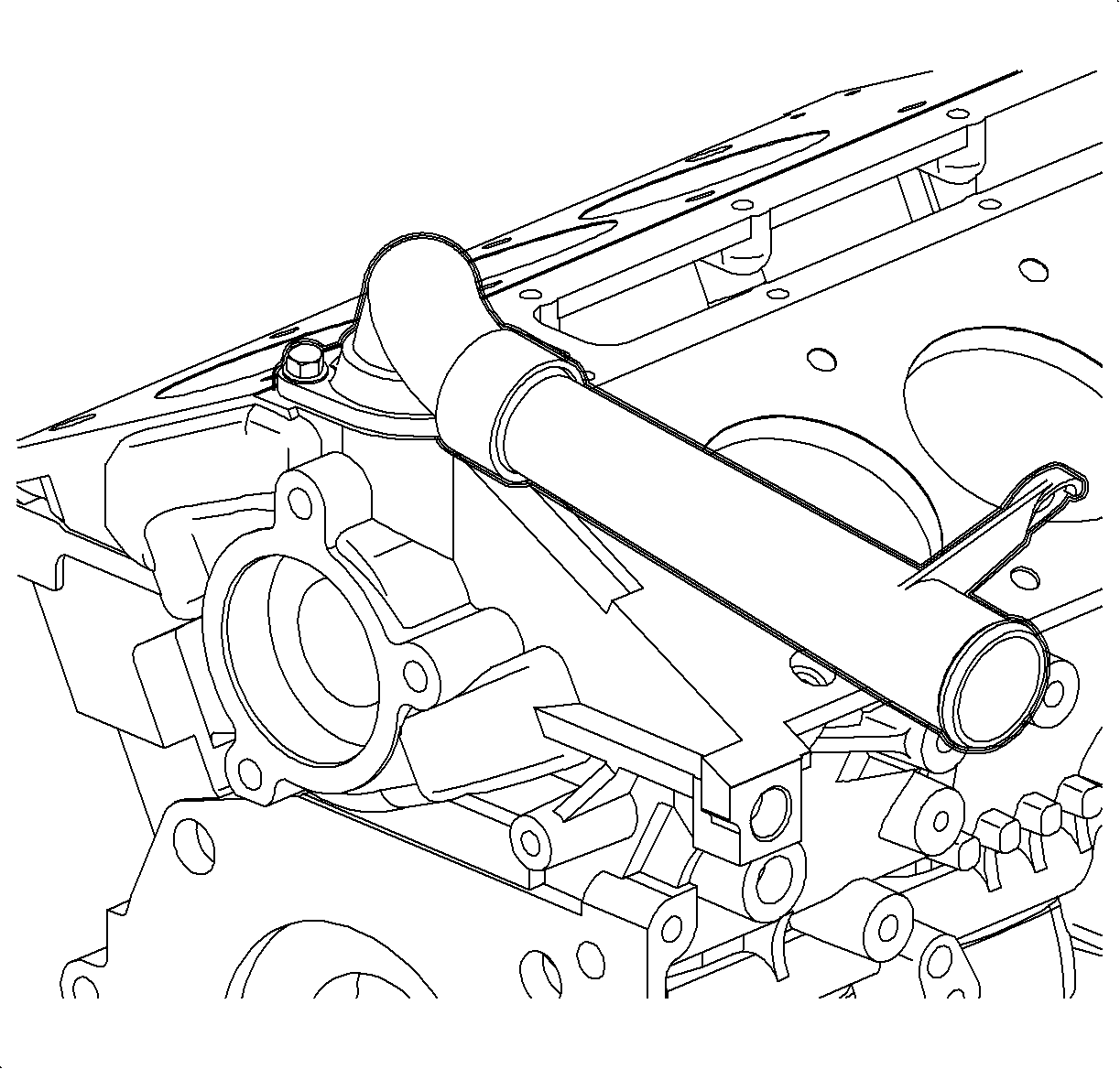
- Remove the oil level indicator tube and coolant extension tube bolt.
- Remove the oil level indicator by pulling upwards.
- Twist the coolant extension housing to remove.
- Remove the power steering pipe bracket bolt.
- Remove the upper exhaust manifold nuts.
- Disconnect the front exhaust manifold pipe HO2S electrical connection.
- Raise the vehicle.
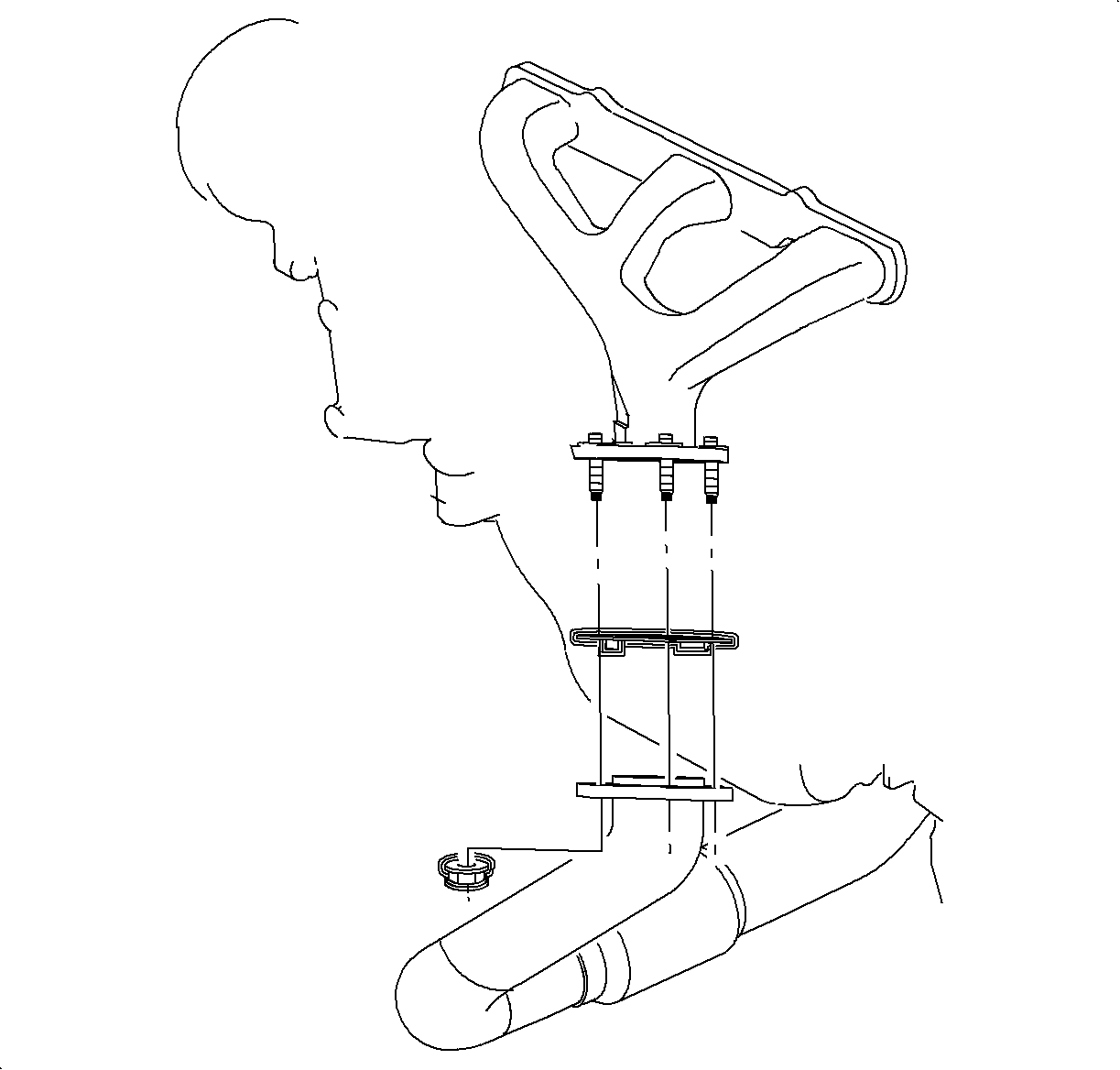
- Remove the front exhaust manifold pipe to exhaust manifold nuts.
- Remove the front exhaust manifold pipe to rear exhaust manifold pipe bolts.
- Remove the front exhaust manifold pipe assembly.
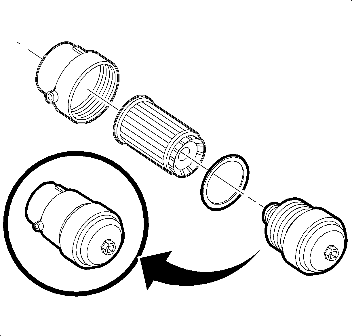
- Remove the oil filter housing assembly.
- Remove the lower exhaust manifold nuts.
- Remove the exhaust manifold and gasket.

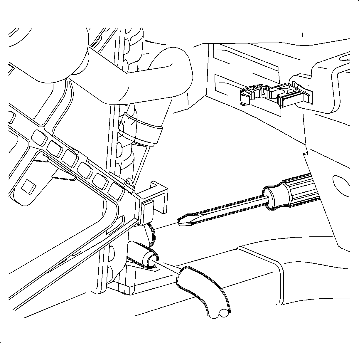
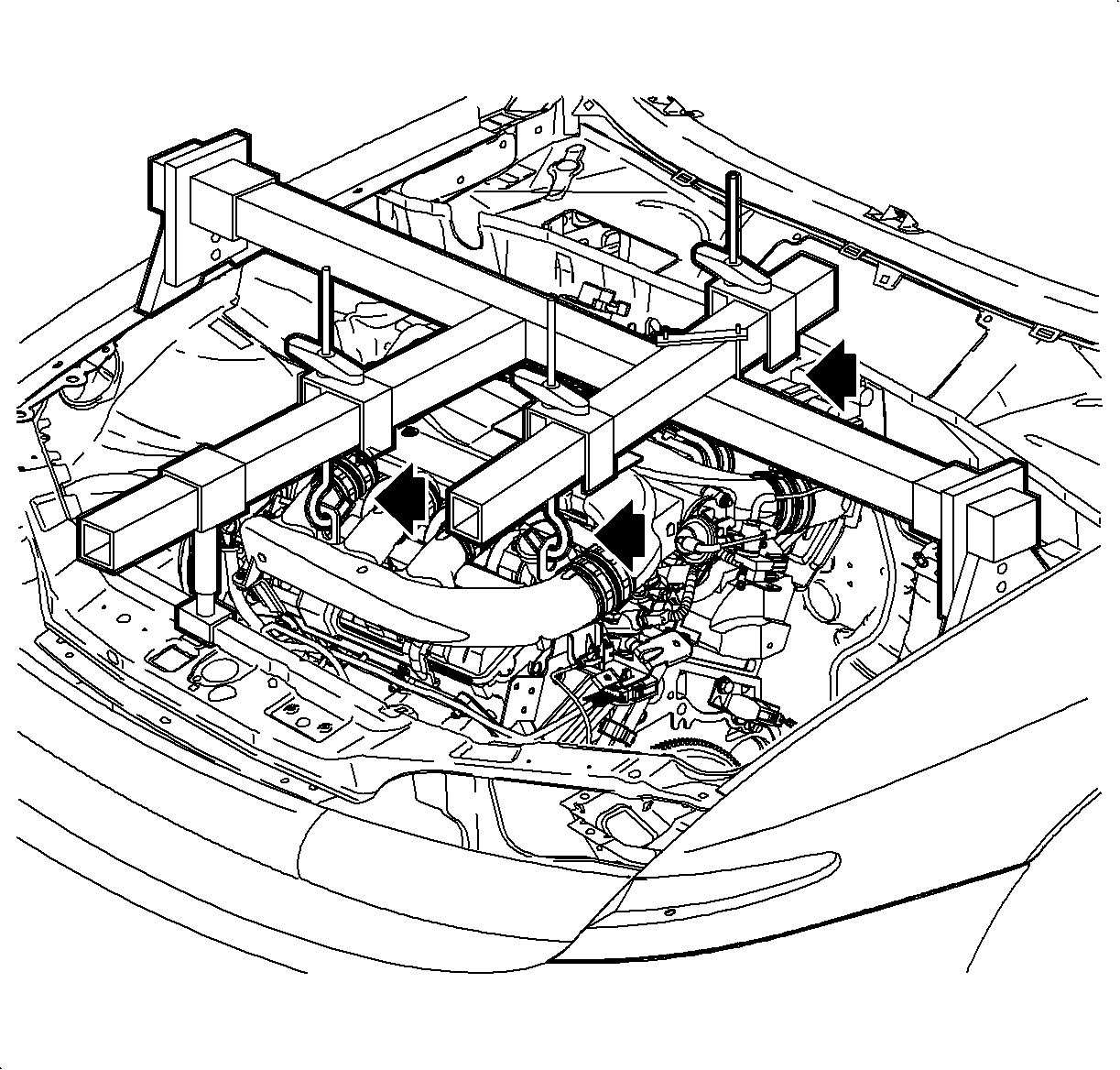
Important: The powertrain must be lifted up in order to remove the coolant extension housing.

Caution: Refer to Vehicle Lifting Caution in the Preface section.


Installation Procedure
- Install the exhaust manifold and new gasket.
- Install the lower exhaust manifold nuts.
- Install the oil filter housing to block.
- Install the oil filter cap and filter to housing.
- Install the front exhaust manifold pipe assembly and gaskets.
- Install the front exhaust manifold pipe to rear exhaust manifold pipe bolts.
- Install the front exhaust manifold pipe to exhaust manifold nuts.
- Tighten the front exhaust manifold pipe to rear exhaust manifold pipe bolts.
- Install the front exhaust manifold pipe HO2S.
- Lower the vehicle.
- Connect the front exhaust manifold pipe HO2S electrical connection.
- Install the upper exhaust manifold nuts.
- Install the power steering pipe bracket bolt.
- Install 2 new O-rings onto the coolant extension housing.
- Lubricate the O-rings with coolant and install the extension housing.
- Install the oil level indicator tube and coolant extension housing bolt.
- Lower the powertrain and align the front transaxle mount and mounting bracket using the engine support fixture.
- Install the front transaxle mount through bolt.
- Remove the SA9105E , or equivalent.
- Install the upper radiator hose.
- Refill the coolant.
- Install the exhaust manifold HO2S using the J 39194-C .
- Connect the exhaust manifold HO2S electrical connection.
- Start the vehicle and check for coolant and exhaust leaks.

Notice: Refer to Fastener Notice in the Preface section.
Tighten
Tighten the exhaust manifold nut to 20 N·m
(15 lb ft).

Tighten
Tighten the oil filter cartridge housing-to-engine
to 45 N·m (33 lb ft).
Tighten
Tighten the oil filter cap to 15 N·m
(11 lb ft).

Important: Do not tighten the fasteners.

Tighten
Tighten the exhaust manifold pipe-to-exhaust manifold
nuts to 30 N·m (25 lb ft).
Tighten
Tighten the exhaust manifold pipe bolts to 20 N·m
(15 lb ft).

Notice: Always use a nickle-based anti-seize compound Saturn P/N 21485279 (or equivalent) on the threads of the heated oxygen sensor (H02S-2). If the H02S-2 is replaced, do not apply anti-seize to the new sensor. New sensors have anti-seize pre-applied. Never use silicone products. Silicone products will damage the sensor.
Tighten
Tighten the oxygen sensors (lower exhaust pipe)
to 45 N·m (33 lb ft).

Tighten
Tighten the exhaust manifold nut to 20 N·m
(15 lb ft).
Tighten
Tighten the power steering pipe bracket bolt to
8 N·m (71 lb in).

Tighten
Tighten the coolant extension housing bolt to 20 N·m
(15 lb ft).


Tighten
Tighten the transaxle mount through bolt to 55 N·m
(41 lb ft).



Tighten
Tighten the oxygen sensors (exhaust manifold) to
50 N·m (37 lb ft).
