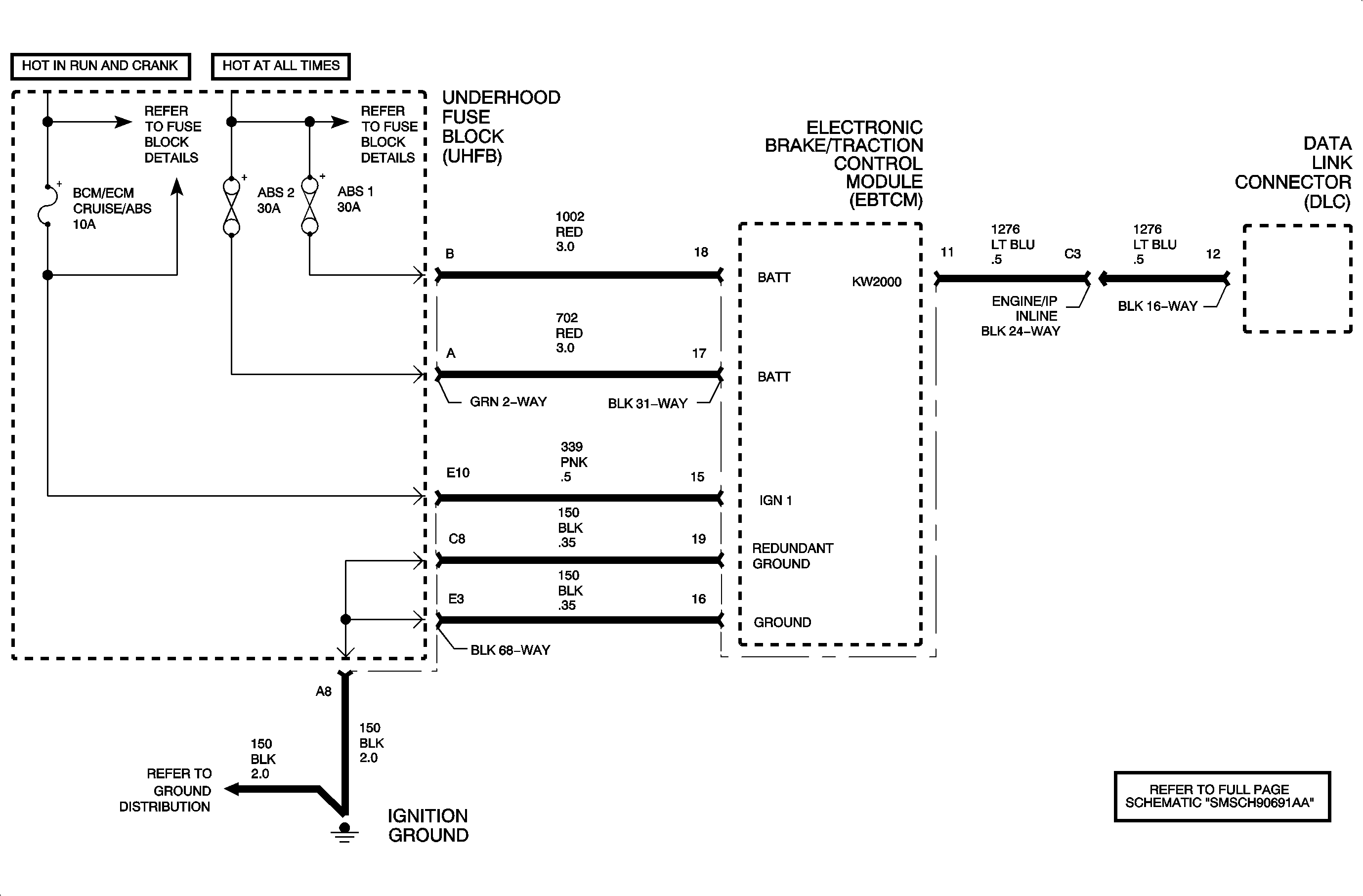
Circuit Description
The electronic brake control module (EBCM) is required to operate within a specified range of voltage to function properly. During antilock brake system (ABS) and traction control system (TCS) operation, there are current requirements that will cause the voltage to drop. Because of this, voltage is monitored out of ABS/TCS control to indicate a good charging system condition, and also during ABS/TCS control when voltage may drop significantly. The EBCM also monitors for high voltage conditions which could damage the EBCM.
Conditions for Running the DTC
The vehicle speed is above 6.4 km/h (4 mph)
Conditions for Setting the DTC
The battery voltage drops below 9.4 volts or exceeds 17.4 volts
Action Taken When the DTC Sets
| • | The ABS telltale will be turned ON. |
| • | The ABS control module will disable the ABS, the TCS, and the DRP. |
Conditions for Clearing the DTC
The Conditions for Setting the DTC are no longer present and you use the scan tool Clear DTCs function.
Diagnostic Aids
Important: If the battery voltage returns to normal levels 9.4-17.4 volts within the same ignition cycle, the ABS control module will enable ABS/TCS/DRP and will turn the ABS telltale off.
Use the scan tool to observe the battery voltage display.
Refer to Starting/Charging section the appropriate Engine service manual for charge circuit diagnosis.
Step | Action | Values | Yes | No |
|---|---|---|---|---|
Schematic Reference: Antilock Brake System Schematics Connector End View Reference: Antilock Brake System Connector End Views | ||||
1 | Did you performs the ABS Diagnostic System Check? | -- | Go to Step 2 | |
2 |
Does the DTC set? | -- | Go to Step 3 | Go to Diagnostic Aids |
3 | With the engine running turn on all accessories. Use the scan tool in order to monitor the battery voltage in the ABS data display. Is the battery voltage below the specified value? | 12.6 V | Go to Step 4 | Go to Diagnostic Aids |
4 | Using the scan tool monitor the battery voltage in the ECM/PCM data list. Is the battery voltage below the specified value? | 12.6 V | Go to Charging system | Go to Step 5 |
5 | Test the battery positive voltage circuits for an open. Refer to Circuit Testing and Wiring Repairs in Wiring Systems. Did you find and correct the condition? | -- | Go to Step 7 | Go to Step 6 |
6 |
Important: Following EBCM replacement, perform the set-up procedure for the EBCM and perform the Yaw Rate Reference Table Reset Procedure. Use the scan tool to perform the Tire Size Calibration procedure. Replace the EBCM. Refer to Electronic Brake Control Module Replacement . Did you complete the replacement? | -- | Go to Step 7 | -- |
7 |
Does the DTC reset? | -- | Go to Step 2 | System OK |
