|
| ||||||||||||||
|---|---|---|---|---|---|---|---|---|---|---|---|---|---|---|---|
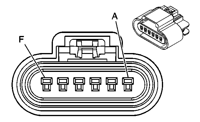
Connector Part Information |
| Connector Part Information |
| ||||||||||||
Pin | Wire Color | Circuit No. | Function | Pin | Wire Color | Circuit No. | Function | ||||||||
A | OG | 140 | Battery Positive Voltage | A | OG | 140 | Battery Positive Voltage | ||||||||
B | BN | 9 | Park Lamp Supply Voltage | B | BN | 9 | Park Lamp Supply Voltage | ||||||||
C | D-BU | 15 | Right Turn Signal Lamps Supply Voltage | C | D-BU | 15 | Right Turn Signal Lamps Supply Voltage | ||||||||
D | PK | 1200 | High Beam Switched Ground | D | PK | 1200 | High Beam Switched Ground | ||||||||
E | L-BU | 1201 | Low Beam Switched Ground | E | L-BU | 1201 | Low Beam Switched Ground | ||||||||
F | BK | 150 | Ground | F | BK | 150 | Ground | ||||||||

|

| ||||||||||||||
|---|---|---|---|---|---|---|---|---|---|---|---|---|---|---|---|
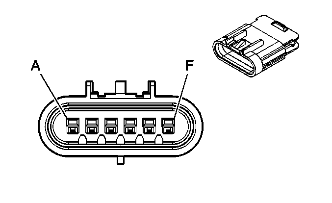
Connector Part Information |
| Connector Part Information |
| ||||||||||||
Pin | Wire Color | Circuit No. | Function | Pin | Wire Color | Circuit No. | Function | ||||||||
A | OG | 40 | Battery Positive Voltage | A | OG | 40 | Battery Positive Voltage | ||||||||
B | BN | 9 | Park Lamp Supply Voltage | B | BN | 9 | Park Lamp Supply Voltage | ||||||||
C | L-BU | 14 | Left Turn Signal Lamps Supply Voltage | C | L-BU | 14 | Left Turn Signal Lamps Supply Voltage | ||||||||
D | PK | 1200 | High Beam Switched Ground | D | PK | 1200 | High Beam Switched Ground | ||||||||
E | L-BU | 1201 | Low Beam Switched Ground | E | L-BU | 1201 | Low Beam Switched Ground | ||||||||
F | BK | 150 | Ground | F | BK | 150 | Ground | ||||||||
| -- | ||||||||||||||
|---|---|---|---|---|---|---|---|---|---|---|---|---|---|---|---|
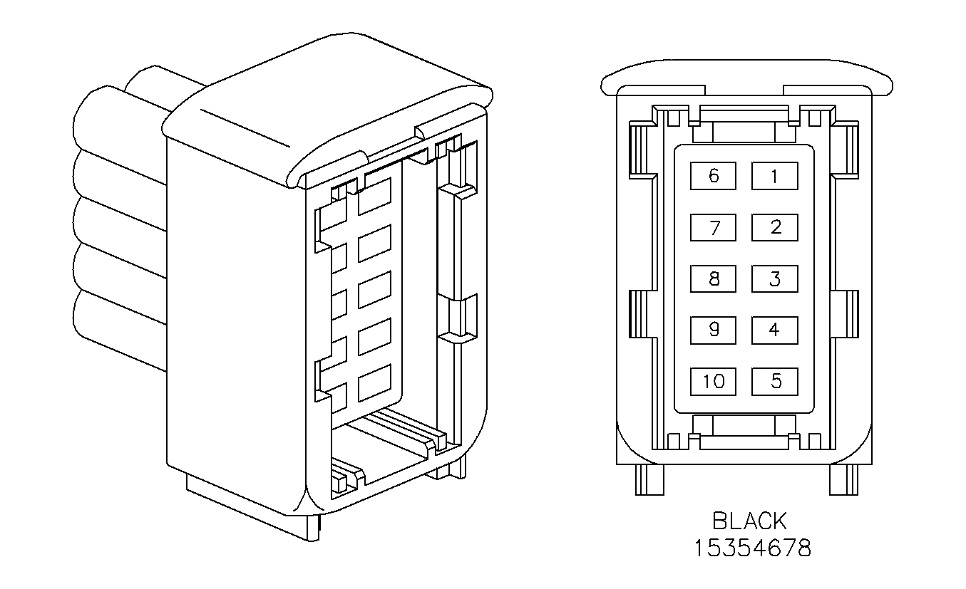
Connector Part Information |
| Connector Part Information |
| ||||||||||||
Pin | Wire Color | Circuit No. | Function | Pin | Wire Color | Circuit No. | Function | ||||||||
1 | BK | 1744 | Fuel Injector 1 Control | 1 | BK | 1744 | Fuel Injector 1 Control | ||||||||
2 | GN/BK | 1745 | Fuel Injector 2 Control | 2 | GN/BK | 1745 | Fuel Injector 2 Control | ||||||||
3 | PK/BK | 1746 | Fuel Injector 3 Control | 3 | PK/BK | 1746 | Fuel Injector 3 Control | ||||||||
4 | BU/BK | 844 | Fuel Injector 4 Control | 4 | BU/BK | 844 | Fuel Injector 4 Control | ||||||||
5 | BK/WH | 845 | Fuel Injector 5 Control | 5 | BK/WH | 845 | Fuel Injector 5 Control | ||||||||
6 | YE/BK | 846 | Fuel Injector 6 Control | 6 | YE/BK | 846 | Fuel Injector 6 Control | ||||||||
7 | -- | -- | Not Used | 7 | -- | -- | Not Used | ||||||||
8 | OG | 2640 | Ignition 1 Voltage | 8 | OG | 2640 | Ignition 1 Voltage | ||||||||
|
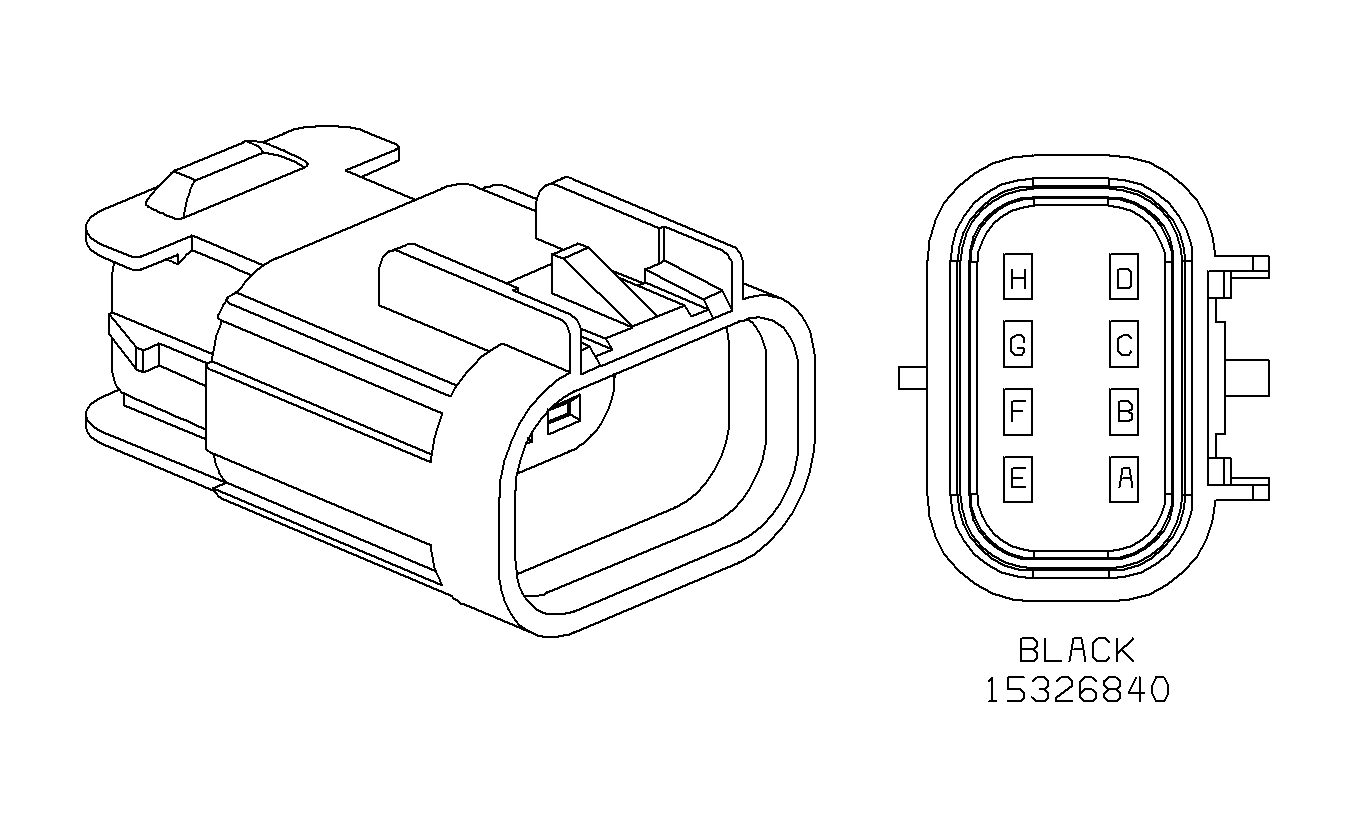
| ||||||||||||||
|---|---|---|---|---|---|---|---|---|---|---|---|---|---|---|---|
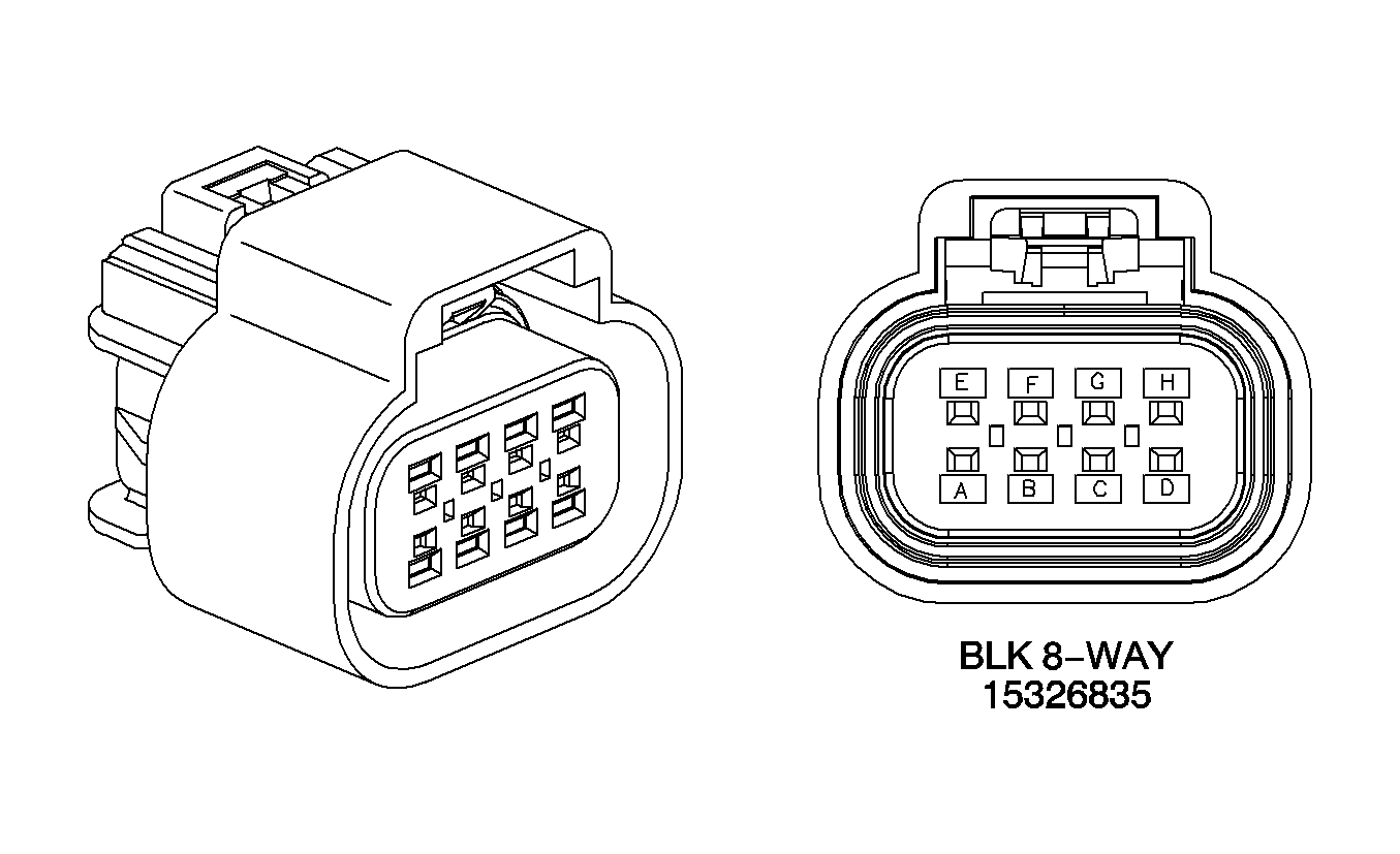
Connector Part Information |
| Connector Part Information |
| ||||||||||||
Pin | Wire Color | Circuit No. | Function | Pin | Wire Color | Circuit No. | Function | ||||||||
A | BK | 1744 | Injector 1 Control | A | BK | 1744 | Injector 1 Control | ||||||||
B | L-GN/BK | 1745 | Injector 2 Control | B | L-GN/BK | 1745 | Injector 2 Control | ||||||||
C | PK/BK | 1746 | Injector 3 Control | C | PK/BK | 1746 | Injector 3 Control | ||||||||
D | L-BU/BK | 844 | Injector 4 Control | D | L-BU/BK | 844 | Injector 4 Control | ||||||||
E | PK | 139 | Ignition 1 Voltage | E | PK | 139 | Ignition 1 Voltage | ||||||||
F | OG/BK | 469 | Low Reference | F | OG/BK | 469 | Low Reference | ||||||||
G | GN | 432 | MAP Sensor Signal | G | L-GN | 432 | MAP Sensor Signal | ||||||||
H | GY | 2704 | 5 Volt Reference | H | GY | 2704 | 5 Volt Reference | ||||||||
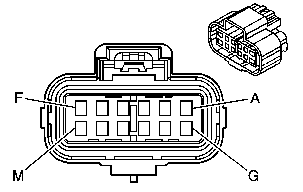
|
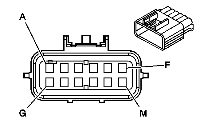
| ||||||||||||||
|---|---|---|---|---|---|---|---|---|---|---|---|---|---|---|---|
Connector Part Information |
| Connector Part Information |
| ||||||||||||
Pin | Wire Color | Circuit No. | Function | Pin | Wire Color | Circuit No. | Function | ||||||||
A | D-BU | 84 | Cruise Control Set/Coast Switch Signal | A1 | D-BU | 84 | Cruise Control Set/Coast Switch Signal | ||||||||
B | BK | 2759 | Low Reference | A2 | BK | 2759 | Low Reference | ||||||||
C | L-BU | 1162 | APP Sensor 2 Signal | A3 | L-BU | 1162 | APP Sensor 2 Signal | ||||||||
D | BN | 86 | Cruise Control Release Signal | A4 | BN | 86 | Cruise Control Release Signal | ||||||||
E | BN | 1271 | Low Reference | A5 | BN | 1271 | Low Reference | ||||||||
F | GY | 397 | Cruise Control On Switch Signal | A6 | GY | 397 | Cruise Control On Switch Signal | ||||||||
G | D-BU | 1161 | APP Sensor 1 Signal | A7 | D-BU | 1161 | APP Sensor 1 Signal | ||||||||
H | TN | 1274 | 5 Volt Reference | A8 | TN | 1274 | 5 Volt Reference | ||||||||
J | WH/BK | 1164 | 5 Volt Reference | B1 | WH/BK | 1164 | 5 Volt Reference | ||||||||
K | PU | 1319 | Engine/Radio Serial Data K-Line | B2 | PU | 1319 | Engine/Radio Serial Data K-Line | ||||||||
L | GY | 2709 | 5 Volt Reference | B3 | GY | 2709 | 5 Volt Reference | ||||||||
M | WH | 1310 | EVAP Canister Vent Solenoid Control | B4 | WH | 1310 | EVAP Canister Vent Solenoid Control | ||||||||
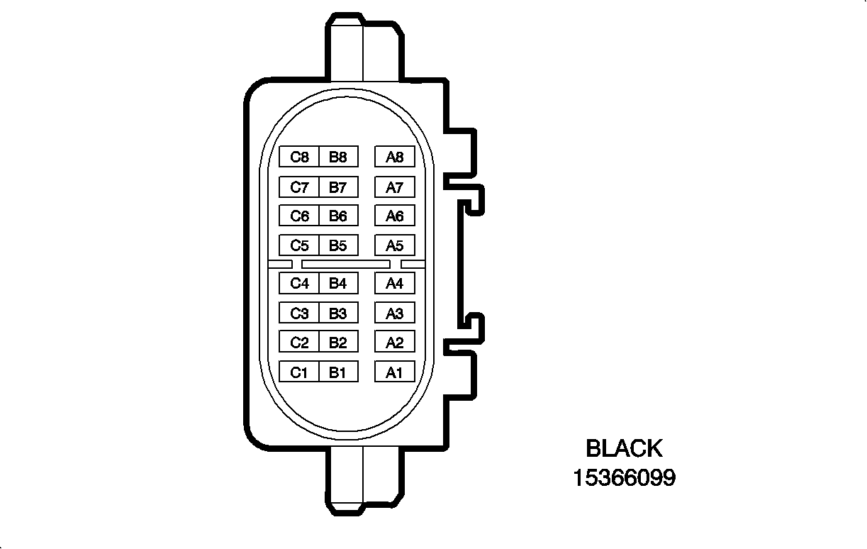
|
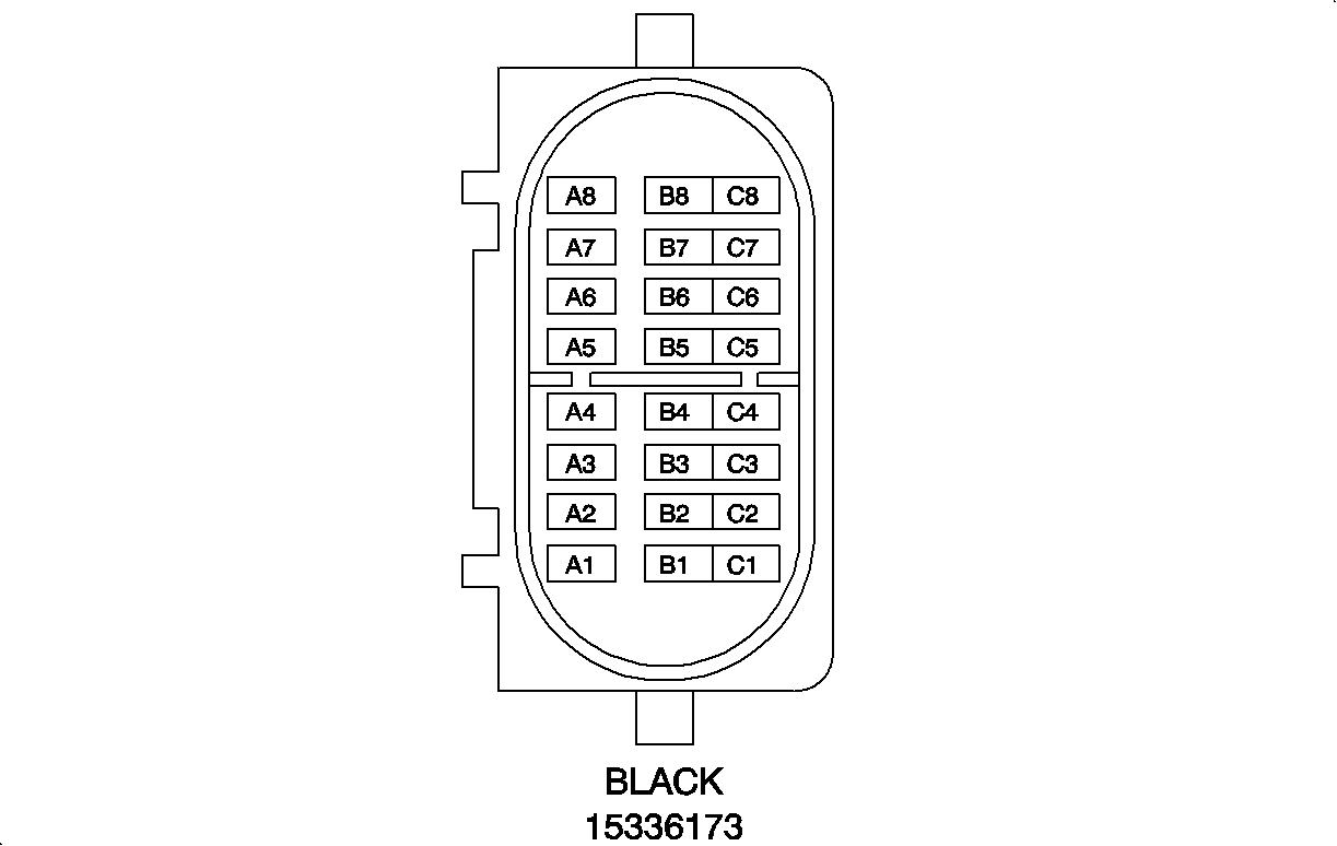
| ||||||||||||||
|---|---|---|---|---|---|---|---|---|---|---|---|---|---|---|---|
Connector Part Information |
| Connector Part Information |
| ||||||||||||
Pin | Wire Color | Circuit No. | Function | Pin | Wire Color | Circuit No. | Function | ||||||||
A1 | BK/WH | 451 | Ground | A1 | BK/WH | 451 | Ground | ||||||||
A2 | WH | 776 | Transmission Range Switch Signal P (A/T) | A2 | BN/WH | 776 | Transmission Range Switch Signal P (A/T) | ||||||||
BN/WH | 379 | CPP Switch Signal (M/T) | PU | 379 | CPP Switch Signal (M/T) | ||||||||||
A3 | PU | 30 | Fuel Level Sensor Signal | A3 | PU | 30 | Fuel Level Sensor Signal | ||||||||
A4 | YE | 5 | Crank Voltage (A/T) | A4 | YE | 5 | Crank Voltage (A/T) | ||||||||
PU | 6 | Starter Solenoid Crank Voltage (M/T) | PU | 6 | Starter Solenoid Crank Voltage (M/T) | ||||||||||
A5 | WH | 1310 | EVAP Canister Vent Solenoid Control | A5 | WH | 1310 | EVAP Canister Vent Solenoid Control | ||||||||
A6 | BK/WH | 451 | Ground | A6 | BK/WH | 451 | Ground | ||||||||
A7 | D- GN/WH | 817 | Vehicle Speed Signal | A7 | D- GN/WH | 817 | Vehicle Speed Signal | ||||||||
A8 | L-BU/BK | 396 | Cruise Control Engaged Signal | A8 | L-BU/BK | 396 | Cruise Control Engaged Signal | ||||||||
B1 | D- GN | 890 | Fuel Tank Pressure Sensor Signal | B1 | D- GN | 890 | Fuel Tank Pressure Sensor Signal | ||||||||
B2 | BK | 2759 | Low Reference | B2 | BK | 2759 | Low Reference | ||||||||
B3 | GY | 2709 | 5 Volt Reference | B3 | GY | 2709 | 5 Volt Reference | ||||||||
B4 | YE | 343 | Accessory Voltage | B4 | YE | 343 | Accessory Voltage | ||||||||
B5 | PU | 1807 | Class 2 Serial Data | B5 | PU | 1807 | Class 2 Serial Data | ||||||||
B6 | BN | 882 | Right Rear Wheel Speed Sensor Signal (w/ ABS) | B6 | BN | 882 | Right Rear Wheel Speed Sensor Signal (w/ ABS) | ||||||||
BN | 872 | Right Rear Wheel Speed Sensor Signal (w/o ABS) | BN | 872 | Right Rear Wheel Speed Sensor Signal (w/o ABS) | ||||||||||
B7 | WH | 883 | Right Rear Wheel Speed Sensor Low Reference (w/ ABS) | B7 | WH | 883 | Right Rear Wheel Speed Sensor Low Reference (w/ ABS) | ||||||||
WH | 833 | Right Front Wheel Speed Sensor Low Reference (w/o ABS) | WH | 833 | Right Front Wheel Speed Sensor Low Reference (w/o ABS) | ||||||||||
B8 | D- GN | 83 | Cruise Control Inhibit Signal | B8 | D- GN | 83 | Cruise Control Inhibit Signal | ||||||||
C1 | YE | 772 | Transmission Range Switch Signal B (A/T) | C1 | YE | 772 | Transmission Range Switch Signal B (A/T) | ||||||||
WH | 1909 | Right Front Wheel Speed Sensor Signal (M/T) | WH | 1909 | Right Front Wheel Speed Sensor Signal (M/T) | ||||||||||
C2 | L-BU | 1788 | Traction Control Switch Signal | C2 | L-BU | 1788 | Traction Control Switch Signal | ||||||||
C3 | L-BU | 1276 | ABS Serial Data K-Line | C3 | L-BU | 1276 | ABS Serial Data K-Line | ||||||||
C4 | PU | 92 | Windshield Wiper Motor High Speed | C4 | PU | 92 | Windshield Wiper Motor High Speed | ||||||||
C5 | D- GN | 95 | Windshield Washer Switch Signal | C5 | D- GN | 95 | Windshield Washer Switch Signal | ||||||||
C6 | BK | 884 | Left Rear Wheel Speed Sensor Signal | C6 | BK | 884 | Left Rear Wheel Speed Sensor Signal | ||||||||
C7 | RD | 885 | Left Rear Wheel Speed Sensor Low Reference | C7 | RD | 885 | Left Rear Wheel Speed Sensor Low Reference | ||||||||
C8 | PU | 1807 | Class 2 Serial Data | C8 | PU | 1807 | Class 2 Serial Data | ||||||||
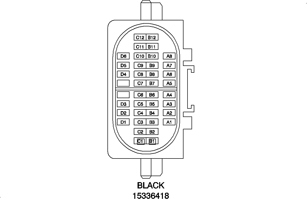
|
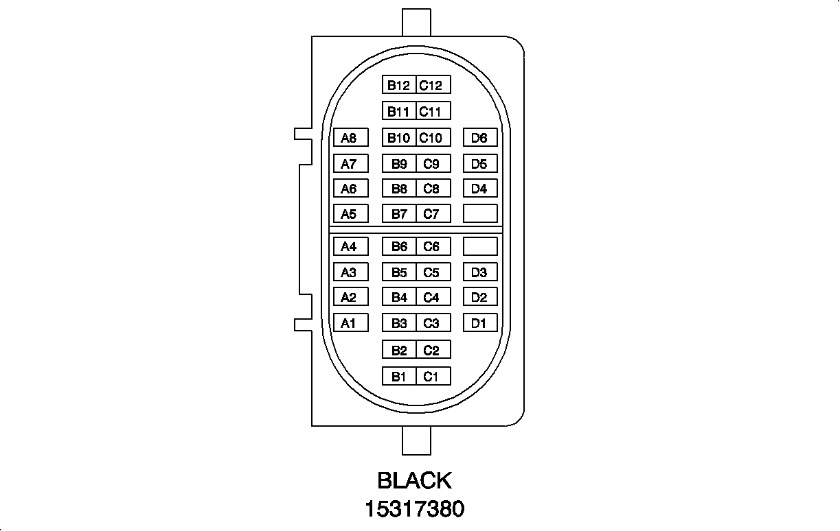
| ||||||||||||||
|---|---|---|---|---|---|---|---|---|---|---|---|---|---|---|---|
Connector Part Information |
| Connector Part Information |
| ||||||||||||
Pin | Wire Color | Circuit No. | Function | Pin | Wire Color | Circuit No. | Function | ||||||||
A1 | GY/BK | 87 | Cruise Control Resume/Accel Switch Signal | A1 | GY/BK | 87 | Cruise Control Resume/Accel Switch Signal | ||||||||
A2 | WH | 776 | Transmission Range Switch Signal P | A2 | WH | 776 | Transmission Range Switch Signal P | ||||||||
A3 | PU | 30 | Fuel Level Sensor Signal | A3 | PU | 30 | Fuel Level Sensor Signal | ||||||||
A4 | YE | 5 | Crank Voltage | A4 | YE | 5 | Crank Voltage | ||||||||
A5 | PU | 1319 | Engine/Radio Serial Data K-Line | A5 | PU | 1319 | Engine/Radio Serial Data K-Line | ||||||||
A6 | TN | 2501 | CAN Low | A6 | TN | 2501 | CAN Low | ||||||||
A7 | TN/WH | 2500 | CAN High | A7 | TN/WH | 2500 | CAN High | ||||||||
A8 | D- GN | 890 | Fuel Tank Pressure Sensor Signal | A8 | D- GN | 890 | Fuel Tank Pressure Sensor Signal | ||||||||
B1 | BK | 2759 | Low Reference | B1 | BK | 2759 | Low Reference | ||||||||
B2 | GY | 2709 | 5 Volt Reference | B2 | GY | 2709 | 5 Volt Reference | ||||||||
B3 | BN | 882 | Right Rear Wheel Speed Sensor Signal | B3 | BN | 882 | Right Rear Wheel Speed Sensor Signal | ||||||||
B4 | WH | 883 | Right Rear Wheel Speed Sensor Low Reference | B4 | WH | 883 | Right Rear Wheel Speed Sensor Low Reference | ||||||||
TN | 833 | Right Front Wheel Speed Sensor Low Reference | |||||||||||||
B5 | D- BLU | 84 | Cruise Control Set/Coast Switch Signal | B5 | D- BLU | 84 | Cruise Control Set/Coast Switch Signal | ||||||||
B6 | YE | 343 | Accessory Voltage | B6 | YE | 343 | Accessory Voltage | ||||||||
B7 | -- | -- | Not Used | B7 | -- | -- | Not Used | ||||||||
B8 | BK | 2759 | Low Reference | B8 | BK | 2759 | Low Reference | ||||||||
B9 | L-BU | 1162 | APP Sensor 2 Signal | B9 | L-BU | 1162 | APP Sensor 2 Signal | ||||||||
B10 | BN | 86 | Cruise Control Release Signal | B10 | BN | 86 | Cruise Control Release Signal | ||||||||
B11 | BN | 1271 | Low Reference | B11 | BN | 1271 | Low Reference | ||||||||
B12 | GY | 397 | Cruise Control On Switch Signal | B12 | GY | 397 | Cruise Control On Switch Signal | ||||||||
C1 | D- BLU | 1161 | APP Sensor 1 Signal | C1 | D- BLU | 1161 | APP Sensor 1 Signal | ||||||||
C2 | TN | 1274 | 5 Volt Reference | C2 | TN | 1274 | 5 Volt Reference | ||||||||
C3 | WH/BK | 1164 | 5 Volt Reference | C3 | WH/BK | 1164 | 5 Volt Reference | ||||||||
C4 | -- | -- | Not Used | C4 | -- | -- | Not Used | ||||||||
C5 | PU | 1319 | Engine/Radio Serial Data K-Line | C5 | PU | 1319 | Engine/Radio Serial Data K-Line | ||||||||
C6 | PU | 92 | Windshield Wiper Motor High Speed | C6 | PU | 92 | Windshield Wiper Motor High Speed | ||||||||
C7 | D- GN | 95 | Windshield Washer Switch Signal | C7 | D- GN | 95 | Windshield Washer Switch Signal | ||||||||
C8 | GY | 2709 | 5 Volt Reference | C8 | GY | 2709 | 5 Volt Reference | ||||||||
C9 | L-BU | 1788 | Traction Control Switch Signal | C9 | L-BU | 1788 | Traction Control Switch Signal | ||||||||
C10 | WH | 2192 | Traction Ready Indicator Control | C10 | WH | 2192 | Traction Ready Indicator Control | ||||||||
C11 | L-GN | 867 | ABS Indicator Failure Control | C11 | L-GN | 867 | ABS Indicator Failure Control | ||||||||
C12 | L-BU | 832 | Traction Control Active Signal | C12 | L-BU | 832 | Traction Control Active Signal | ||||||||
D1 | L-BU | 1276 | ABS Serial Data K-Line | D1 | L-BU | 1276 | ABS Serial Data K-Line | ||||||||
D2 | BK | 884 | Left Rear Wheel Speed Sensor Signal | D2 | BK | 884 | Left Rear Wheel Speed Sensor Signal | ||||||||
D3 | RD | 885 | Left Rear Wheel Speed Sensor Low Reference | D3 | RD | 885 | Left Rear Wheel Speed Sensor Low Reference | ||||||||
D4-D5 | -- | -- | Not Used | D4-D5 | -- | -- | Not Used | ||||||||
D6 | WH | 1310 | EVAP Canister Vent Solenoid Control | D6 | WH | 1310 | EVAP Canister Vent Solenoid Control | ||||||||
D7 | BK/WH | 451 | Ground | D7 | BK/WH | 451 | Ground | ||||||||
D8 | YE | 772 | Transmission Range Switch Signal B | D8 | YE | 772 | Transmission Range Switch Signal B | ||||||||
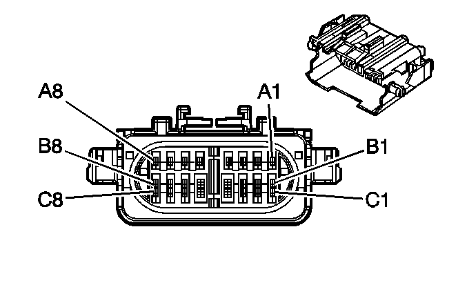
|
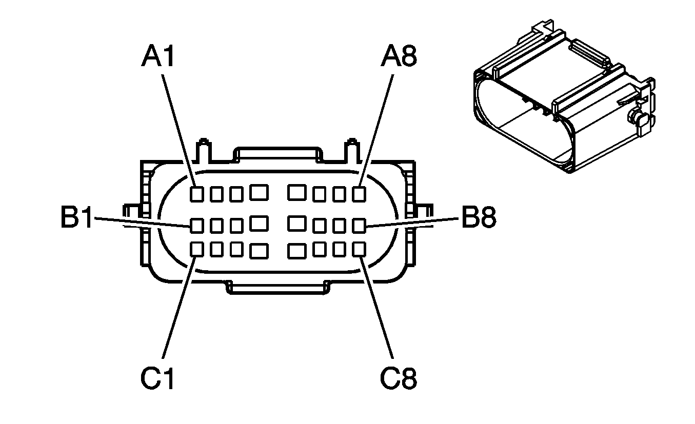
| ||||||||||||||
|---|---|---|---|---|---|---|---|---|---|---|---|---|---|---|---|
Connector Part Information |
| Connector Part Information |
| ||||||||||||
Pin | Wire Color | Circuit No. | Function | Pin | Wire Color | Circuit No. | Function | ||||||||
A1 | GY/BK | 87 | Cruise Control Resume/Accel Switch Signal | A1 | GY/BK | 87 | Cruise Control Resume/Accel Switch Signal | ||||||||
A2 | WH | 776 | Transmission Range Switch Signal P | A2 | WH | 776 | Transmission Range Switch Signal P | ||||||||
A3 | PU | 30 | Fuel Level Sensor Signal | A3 | PU | 30 | Fuel Level Sensor Signal | ||||||||
A4 | YE | 5 | Crank Voltage | A4 | YE | 5 | Crank Voltage | ||||||||
A5 | PU | 1319 | Engine/Radio Serial Data K-Line | A5 | PU | 1319 | Engine/Radio Serial Data K-Line | ||||||||
A6 | TN | 2501 | CAN Low | A6 | TN | 2501 | CAN Low | ||||||||
A7 | TN/WH | 2500 | CAN High | A7 | TN/WH | 2500 | CAN High | ||||||||
A8 | D- GN | 890 | Fuel Tank Pressure Sensor Signal | A8 | D- GN | 890 | Fuel Tank Pressure Sensor Signal | ||||||||
B1 | BK | 2759 | Low Reference | B1 | BK | 2759 | Low Reference | ||||||||
B2 | WH | 883 | Right Rear Wheel Speed Sensor Low Reference | B2 | WH | 883 | Right Rear Wheel Speed Sensor Low Reference | ||||||||
B3 | BN | 882 | Right Rear Wheel Speed Sensor Signal | B3 | BN | 882 | Right Rear Wheel Speed Sensor Signal | ||||||||
B4 | PU | 92 | Windshield Wiper Motor High Speed | B4 | PU | 92 | Windshield Wiper Motor High Speed | ||||||||
B5 | YE | 343 | Accessory Voltage | B5 | YE | 343 | Accessory Voltage | ||||||||
B6 | L-BU | 1788 | Traction Control Switch Signal | B6 | L-BU | 1788 | Traction Control Switch Signal | ||||||||
B7 | WH | 2192 | Traction Ready Indicator Control | B7 | WH | 2192 | Traction Ready Indicator Control | ||||||||
B8 | GY | 2709 | 5 Volt Reference | B8 | GY | 2709 | 5 Volt Reference | ||||||||
C1 | BK/WH | 451 | Ground | C1 | BK/WH | 451 | Ground | ||||||||
C2 | L-GN | 867 | ABS Indicator Failure Control (w/ ABS) | C2 | L-GN | 867 | ABS Indicator Failure Control (w/ ABS) | ||||||||
C3 | L-BU | 832 | Traction Control Active Signal (w/ ABS) | C3 | L-BU | 832 | Traction Control Active Signal (w/ ABS) | ||||||||
C4 | L-BU | 1276 | ABS Serial Data K-Line (w/ ABS) | C4 | L-BU | 1276 | ABS Serial Data K-Line (w/ ABS) | ||||||||
C5 | D-GN | 95 | Windshield Washer Switch Signal | C5 | D-GN | 95 | Windshield Washer Switch Signal | ||||||||
C6 | OG | 885 | Left Rear Wheel Speed Sensor Low Reference (w/ ABS) | C6 | OG | 885 | Left Rear Wheel Speed Sensor Low Reference (w/ ABS) | ||||||||
C7 | TN | 884 | Windshield Washer Switch Signal (w/ ABS) | C7 | TN | 884 | Windshield Washer Switch Signal (w/ ABS) | ||||||||
C8 | YE | 772 | Transmission Range Switch Signal B | C8 | YE | 772 | Transmission Range Switch Signal B | ||||||||
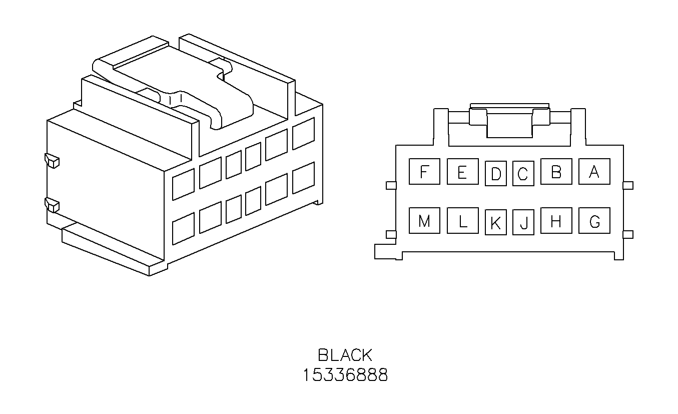
|
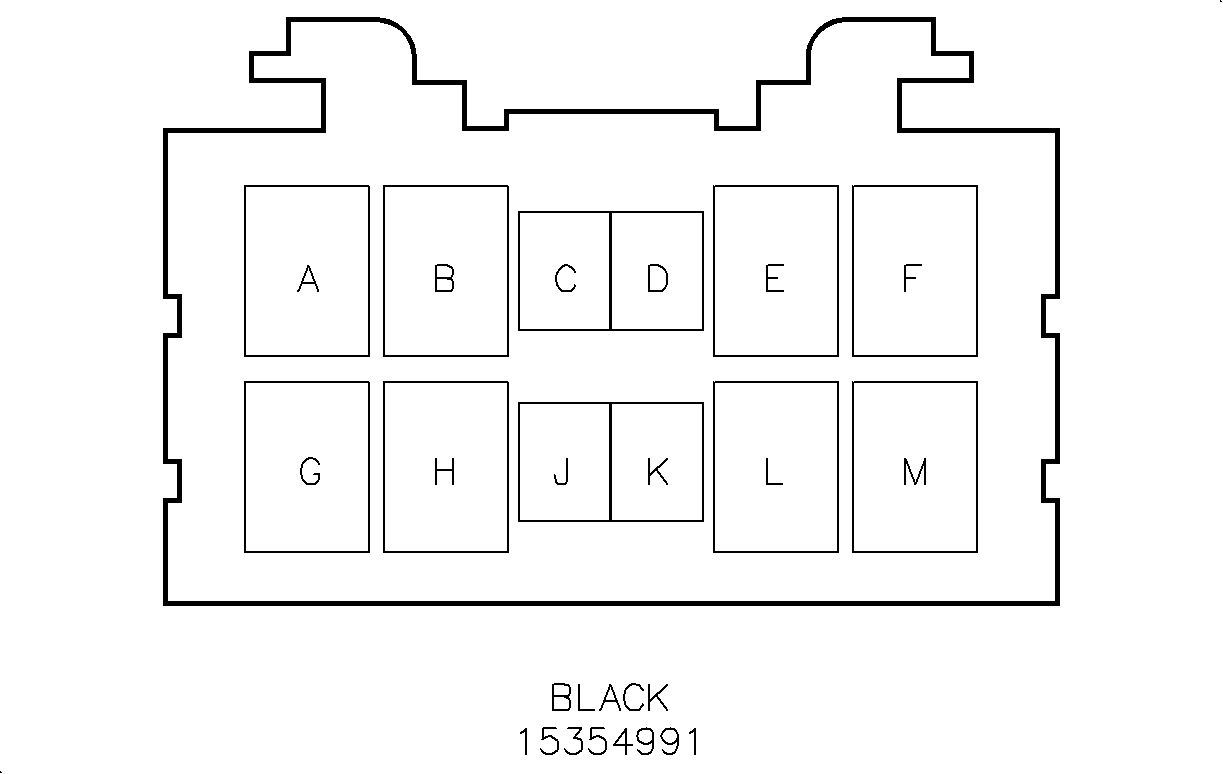
| ||||||||||||||
|---|---|---|---|---|---|---|---|---|---|---|---|---|---|---|---|
Connector Part Information |
| Connector Part Information |
| ||||||||||||
Pin | Wire Color | Circuit No. | Function | Pin | Wire Color | Circuit No. | Function | ||||||||
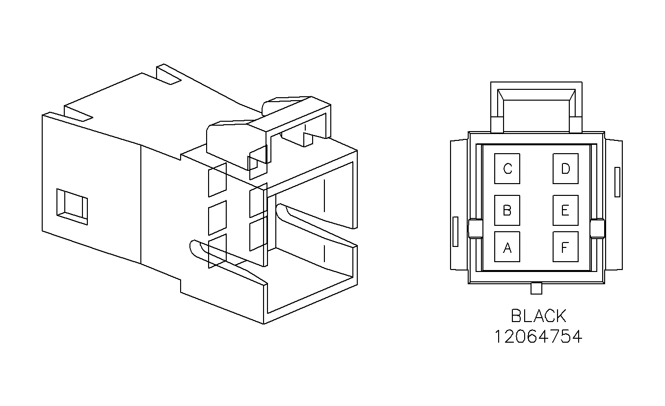
A | OG | 1732 | Courtesy Lamps Supply Voltage | A | OG | 1732 | Courtesy Lamps Supply Voltage | ||||||||
B | OG | 1732 | Courtesy Lamps Supply Voltage | B | OG | 1732 | Courtesy Lamps Supply Voltage | ||||||||
C | L-BU | 20 | Stop Lamp Switch Signal | C | L-BU | 20 | Stop Lamp Switch Signal | ||||||||
OG | 1732 | Courtesy Lamps Supply Voltage (Wagon) | OG | 1732 | Courtesy Lamps Supply Voltage (Wagon) | ||||||||||
D | YE | 143 | Accessory Voltage (Sedan) | D | YE | 143 | Accessory Voltage (Sedan) | ||||||||
E | RD | 402 | Battery Positive Voltage | E | RD | 402 | Battery Positive Voltage | ||||||||
F | WH | 156 | Courtesy Lamp Low Control | F | WH | 156 | Courtesy Lamp Low Control | ||||||||
G | -- | -- | Not Used | G | -- | -- | Not Used | ||||||||
H | BK | 450 | Ground | H | BK | 450 | Ground | ||||||||
J-M | -- | -- | Not Used | J-M | -- | -- | Not Used | ||||||||
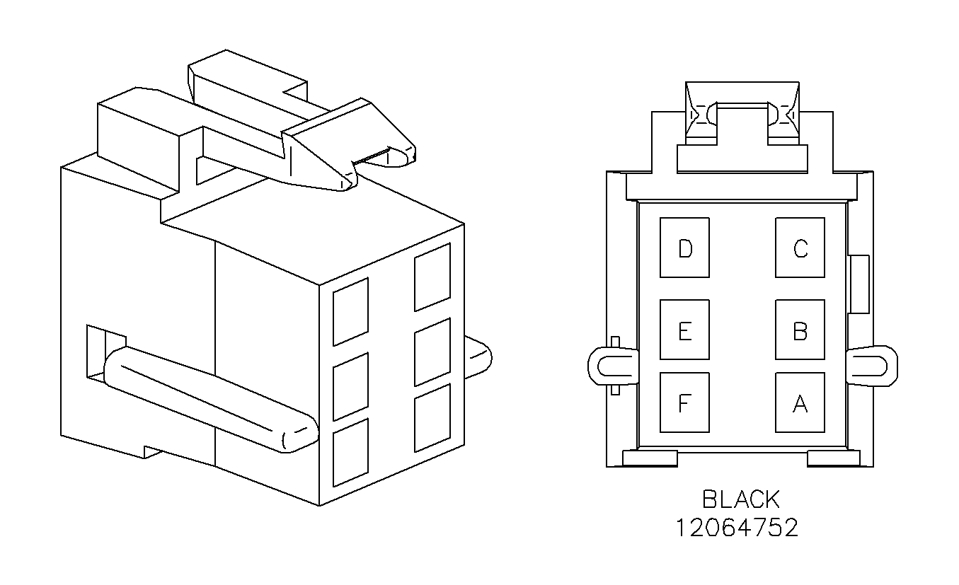
|
| ||||||||||||||
|---|---|---|---|---|---|---|---|---|---|---|---|---|---|---|---|
Connector Part Information |
| Connector Part Information |
| ||||||||||||
Pin | Wire Color | Circuit No. | Function | Pin | Wire Color | Circuit No. | Function | ||||||||
A | BLU | 346 | Subwoofer Speaker Output (+) | A | BLU | 346 | Subwoofer Speaker Output (+) | ||||||||
B | GN | 1794 | Subwoofer Speaker Output (-) | B | GN | 1794 | Subwoofer Speaker Output (-) | ||||||||
C | OG | 1340 | Battery Positive Voltage | C | OG | 1340 | Battery Positive Voltage | ||||||||
D | BK | 450 | Ground | D | BK | 450 | Ground | ||||||||
E-F | -- | -- | Not Used | E-F | -- | -- | Not Used | ||||||||
|
| ||||||||||||||
|---|---|---|---|---|---|---|---|---|---|---|---|---|---|---|---|
Connector Part Information |
| Connector Part Information |
| ||||||||||||
Pin | Wire Color | Circuit No. | Function | Pin | Wire Color | Circuit No. | Function | ||||||||
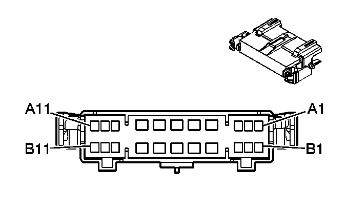
A1 | WH | 156 | Courtesy Lamp Low Control | A1 | WH | 156 | Courtesy Lamp Low Control | ||||||||
A2 | D-GN/WH | 368 | Remote Radio Right Audio Signal | A2 | D-GN/WH | 368 | Remote Radio Right Audio Signal | ||||||||
A3 | BARE | 814 | Drain Wire | A3 | BARE | 814 | Drain Wire | ||||||||
A4 | BK/WH | 746 | Right Front Door Ajar Switch Signal | A4 | BK/WH | 746 | Right Front Door Ajar Switch Signal | ||||||||
BK/WH | 746 | Right Front Door Ajar Switch Signal | BK/WH | 746 | Right Front Door Ajar Switch Signal | ||||||||||
A5 | RD/BK | 744 | Rear Compartment Lid Adjar Switch | A5 | RD/BK | 744 | Rear Compartment Lid Adjar Switch | ||||||||
A6 | GY | 382 | Trunk Release Enable Relay Switch Supply Voltage | A6 | GY | 382 | Trunk Release Enable Relay Switch Supply Voltage | ||||||||
A7 | BK/WH | 746 | Right Front Door Ajar Switch Signal | A7 | BK/WH | 746 | Right Front Door Ajar Switch Signal | ||||||||
A8 | OG | 1732 | Courtesy Lamps Supply Voltage | A8 | OG | 1732 | Courtesy Lamps Supply Voltage | ||||||||
A9 | BN/WH | 367 | Remote Radio Left Audio Signal | A9 | BN/WH | 367 | Remote Radio Left Audio Signal | ||||||||
A10 | YE/BK | 693 | Cellular Telephone Mute Signal | A10 | YE/BK | 693 | Cellular Telephone Mute Signal | ||||||||
A11 | BK/WH | 372 | Remote Radio Audio Output (-) | A11 | BK/WH | 372 | Remote Radio Audio Output (-) | ||||||||
B1 | -- | -- | Not Used | B1 | -- | -- | Not Used | ||||||||
B2 | D-BU | 1363 | Seat Belt Switch - Left - Low Reference | B2 | D-BU | 1363 | Seat Belt Switch - Left - Low Reference | ||||||||
B3 | BK/WH | 238 | Seat Belt Switch - Left | B3 | BK/WH | 238 | Seat Belt Switch - Left | ||||||||
B4 | OG | 1732 | Courtesy Lamps Supply Voltage | B4 | OG | 1732 | Courtesy Lamps Supply Voltage | ||||||||
OG | 1732 | Courtesy Lamps Supply Voltage | OG | 1732 | Courtesy Lamps Supply Voltage | ||||||||||
B5 | D-GN | 117 | Right Front Speaker Output (-) | B5 | D-GN | 117 | Right Front Speaker Output (-) | ||||||||
B6 | L-GN | 200 | Right Front Speaker Output (+) | B6 | L-GN | 200 | Right Front Speaker Output (+) | ||||||||
B7 | PU | 1807 | Class 2 Serial Data | B7 | PU | 1807 | Class 2 Serial Data | ||||||||
PU | 1807 | Class 2 Serial Data | Class 2 Serial Data | ||||||||||||
B8 | D-BU | 46 | Right Rear Speaker Output (+) | B8 | D-BU | 46 | Right Rear Speaker Output (+) | ||||||||
B9 | BK | 650 | Ground | B9 | BK | 650 | Ground | ||||||||
B10 | OG | 1340 | Battery Positive Voltage | B10 | OG | 1340 | Battery Positive Voltage | ||||||||
B11 | L-BU | 115 | Right Rear Speaker Output (-) | B11 | L-BU | 115 | Right Rear Speaker Output (-) | ||||||||
|
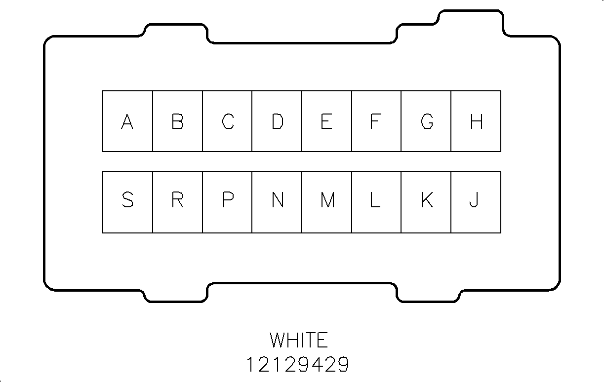
| ||||||||||||||
|---|---|---|---|---|---|---|---|---|---|---|---|---|---|---|---|
Connector Part Information |
| Connector Part Information |
| ||||||||||||
Pin | Wire Color | Circuit No. | Function | Pin | Wire Color | Circuit No. | Function | ||||||||
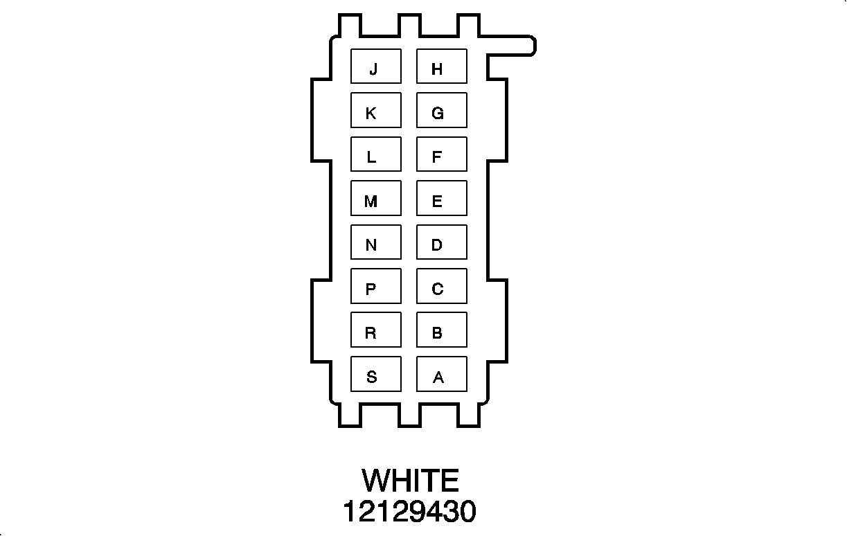
A | D- BLU | 46 | Right Rear Speaker Output (+) | A | D- BLU | 46 | Right Rear Speaker Output (+) | ||||||||
B | L-BU | 115 | Right Rear Speaker Output (-) | B | L-BU | 115 | Right Rear Speaker Output (-) | ||||||||
C | L-GN | 200 | Right Front Speaker Output (+) | C | L-GN | 200 | Right Front Speaker Output (+) | ||||||||
D | D- GN | 117 | Right Front Speaker Output (-) | D | D- GN | 117 | Right Front Speaker Output (-) | ||||||||
E | BK/WH | 238 | Seat Belt Switch - Left | E | BK/WH | 238 | Seat Belt Switch - Left | ||||||||
F | D- BLU | 1363 | Seat Belt Switch - Left - Low Reference | F | D- BLU | 1363 | Seat Belt Switch - Left - Low Reference | ||||||||
G | OG | 1732 | Courtesy Lamps Supply Voltage | G | OG | 1732 | Courtesy Lamps Supply Voltage | ||||||||
H | OG | 1732 | Courtesy Lamps Supply Voltage | H | -- | -- | Courtesy Lamps Supply Voltage | ||||||||
J | WH | 156 | Courtesy Lamp Low Control | J | WH | 156 | Courtesy Lamp Low Control | ||||||||
K | RD/WH | 744 | Rear Compartment Lid Adjar Switch | K | RD/BK | 744 | Rear Compartment Lid Adjar Switch | ||||||||
L | BK/WH | 746 | Right Front Door Ajar Switch Signal | L | BK/WH | 746 | Right Front Door Ajar Switch Signal | ||||||||
M | BK/WH | 746 | Right Front Door Ajar Switch Signal | M | BK/WH | 746 | Right Front Door Ajar Switch Signal | ||||||||
N | GY | 382 | Trunk Release Enable Relay Switch Supply Voltage | N | GY | 382 | Trunk Release Enable Relay Switch Supply Voltage | ||||||||
P-S | -- | -- | Not Used | P-S | -- | -- | Not Used | ||||||||

|
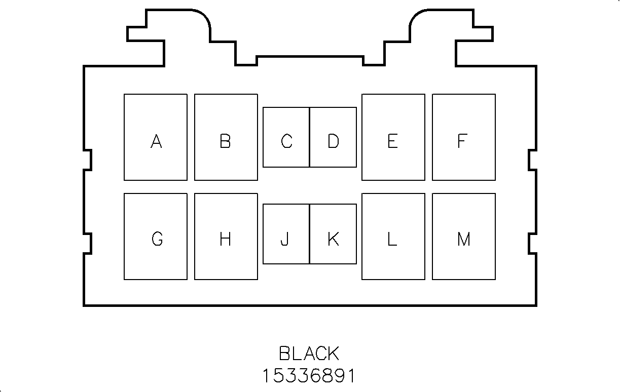
| ||||||||||||||
|---|---|---|---|---|---|---|---|---|---|---|---|---|---|---|---|
Connector Part Information |
| Connector Part Information |
| ||||||||||||
Pin | Wire Color | Circuit No. | Function | Pin | Wire Color | Circuit No. | Function | ||||||||
A | YE | 268 | Ignition 3 Voltage | A | OG/TN | YE | Ignition 3 Voltage | ||||||||
B | TN | 683 | Rear Defog Indicator Supply Voltage | B | OG/YE | TN | Rear Defog Indicator Supply Voltage | ||||||||
C | BK | 550 | Ground | c | BK | BK | Ground | ||||||||
D | YE | 61 | Low Reference | D | L-GN/YE | YE | Low Reference | ||||||||
E | L-BU/BK | 590 | Sunload Sensor Signal | E | BN/L-BU | L-BU/BK | Sunload Sensor Signal | ||||||||
F | BK | 550 | Ground | F | BK | BK | Ground | ||||||||
G | GY | 8 | Instrument Panel Lamp Supply Voltage | G | GY | GY | Instrument Panel Lamp Supply Voltage | ||||||||
H | BN | 641 | Ignition 3 Voltage | H | BN | BN | Ignition 3 Voltage | ||||||||
J | PU | 1807 | Class 2 Serial Data | J | L-BU/PU | PU | Class 2 Serial Data | ||||||||
K | PU | 1807 | Class 2 Serial Data | K | TN/PU | PU | Class 2 Serial Data | ||||||||
L | OG | 1640 | Battery Positive Voltage | L | OG | OG | Battery Positive Voltage | ||||||||
M | BK | 476 | Low Reference | M | BK | 476 | Low Reference | ||||||||
BK | 476 | Low Reference | |||||||||||||

|

| ||||||||||||||
|---|---|---|---|---|---|---|---|---|---|---|---|---|---|---|---|
Connector Part Information |
| Connector Part Information |
| ||||||||||||
Pin | Wire Color | Circuit No. | Function | Pin | Wire Color | Circuit No. | Function | ||||||||
A | OG | 52 | Blower Motor High Control | A | OG | 52 | Blower Motor High Control | ||||||||
B | OG | 52 | Blower Motor High Control | B | OG | 52 | Blower Motor High Control | ||||||||
C | BK | 550 | Ground | c | BK | 550 | Ground | ||||||||
D | L-GN | 66 | A/C Request Signal | D | L-GN | 66 | A/C Request Signal | ||||||||
E | YE | 268 | Ignition 3 Voltage | E | YE | 268 | Ignition 3 Voltage | ||||||||
F | BK | 550 | Ground | F | BK | 550 | Ground | ||||||||
G | GY | 8 | Instrument Panel Lamp Supply Voltage | G | GY | 8 | Instrument Panel Lamp Supply Voltage | ||||||||
H | BN | 641 | Ignition 3 Voltage | H | BN | 641 | Ignition 3 Voltage | ||||||||
J | L-BU | 292 | Rear Defog Switch Signal | J | L-BU | 292 | Rear Defog Switch Signal | ||||||||
K | TN | 683 | Rear Defog Indicator Supply Voltage | K | TN | 683 | Rear Defog Indicator Supply Voltage | ||||||||
L | -- | -- | Not Used | L | -- | -- | Not Used | ||||||||

|

| ||||||||||||||
|---|---|---|---|---|---|---|---|---|---|---|---|---|---|---|---|
Connector Part Information |
| Connector Part Information |
| ||||||||||||
Pin | Wire Color | Circuit No. | Function | Pin | Wire Color | Circuit No. | Function | ||||||||
A | GY | 2709 | 5 Volt Reference | A | GY | 2709 | 5 Volt Reference | ||||||||
B | TN | 201 | Left Front Speaker Output (+) | B | TN | 201 | Left Front Speaker Output (+) | ||||||||
C | D- GN | 890 | Fuel Tank Pressure Sensor Signal | C | D- GN | 890 | Fuel Tank Pressure Sensor Signal | ||||||||
D | BK | 884 | Left Rear Wheel Speed Sensor Signal | D | BK | 884 | Left Rear Wheel Speed Sensor Signal | ||||||||
E | YE | 182 | Heated Seat Control Module Inhibit Signal | E | YE | 182 | Heated Seat Control Module Inhibit Signal | ||||||||
F | WH | 883 | Right Rear Wheel Speed Sensor Low Reference | F | WH | 883 | Right Rear Wheel Speed Sensor Low Reference | ||||||||
G | GY | 118 | Left Front Speaker Output (-) | G | GY | 118 | Left Front Speaker Output (-) | ||||||||
H | BN | 882 | Right Rear Wheel Speed Sensor Signal | H | BN | 882 | Right Rear Wheel Speed Sensor Signal | ||||||||
J | RD | 885 | Left Rear Wheel Speed Sensor Low Reference | J | RD | 885 | Left Rear Wheel Speed Sensor Low Reference | ||||||||
K | PK | 1501 | Driver Heated Seat High/Low Signal | K | PK | 1501 | Driver Heated Seat High/Low Signal | ||||||||
L | BN | 199 | Left Rear Speaker Output (+) | L | BN | 199 | Left Rear Speaker Output (+) | ||||||||
M | YE | 116 | Left Rear Speaker Output (-) | M | YE | 116 | Left Rear Speaker Output (-) | ||||||||
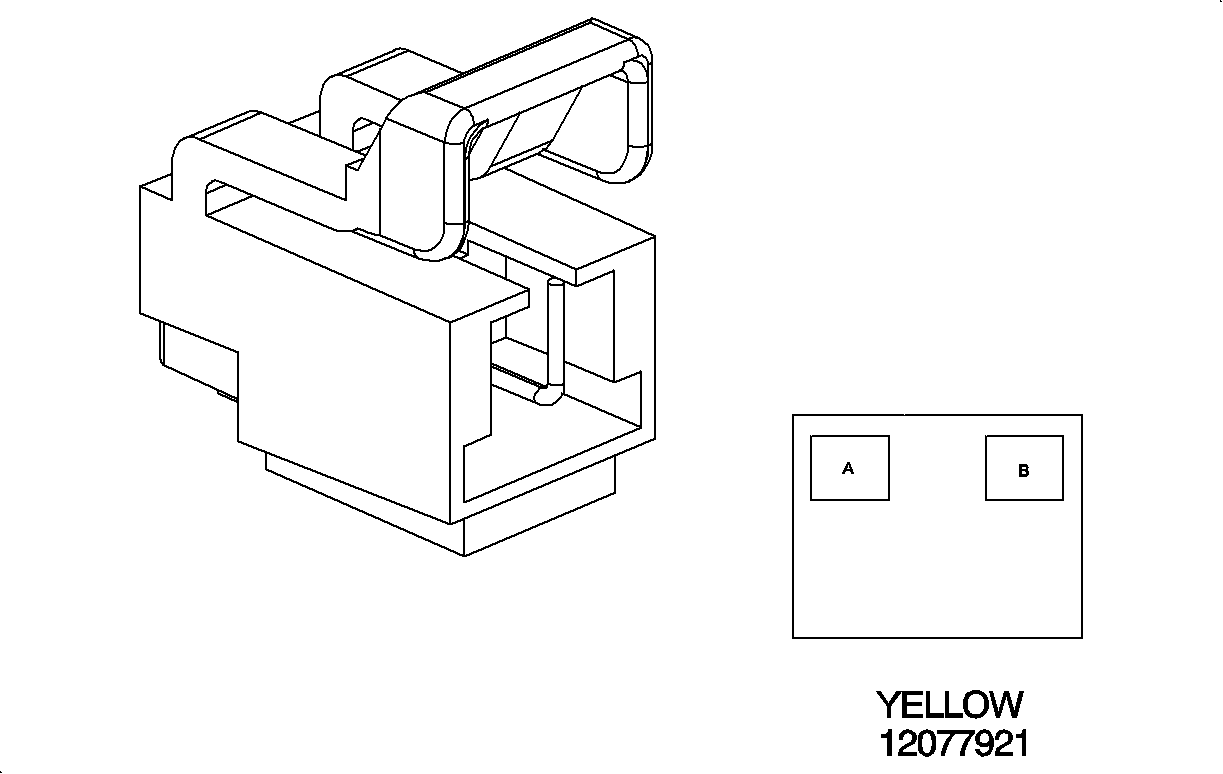
|
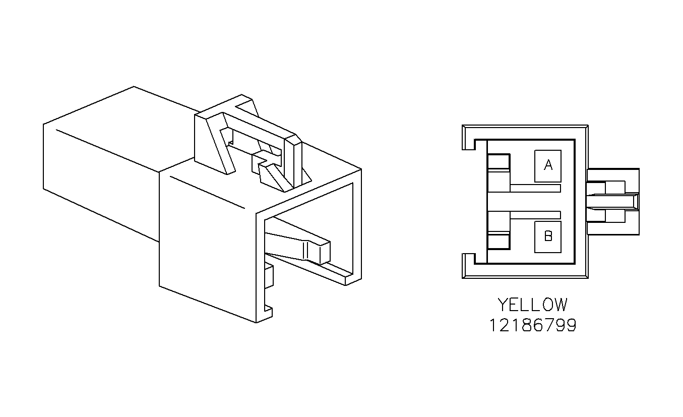
| ||||||||||||||
|---|---|---|---|---|---|---|---|---|---|---|---|---|---|---|---|
Connector Part Information |
| Connector Part Information |
| ||||||||||||
Pin | Wire Color | Circuit No. | Function | Pin | Wire Color | Circuit No. | Function | ||||||||
A | WH/BK | 1403 | I/P Module - High Control | A | WH/BK | 1403 | I/P Module - High Control | ||||||||
B | D- GN/WH | 1404 | I/P Module - Low Control | B | D- GN/WH | 1404 | I/P Module - Low Control | ||||||||
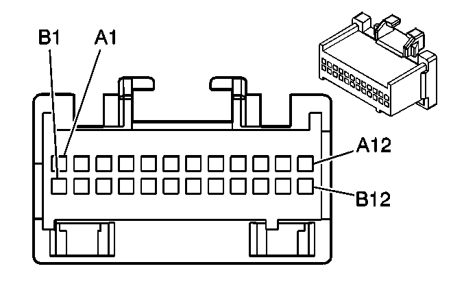
|
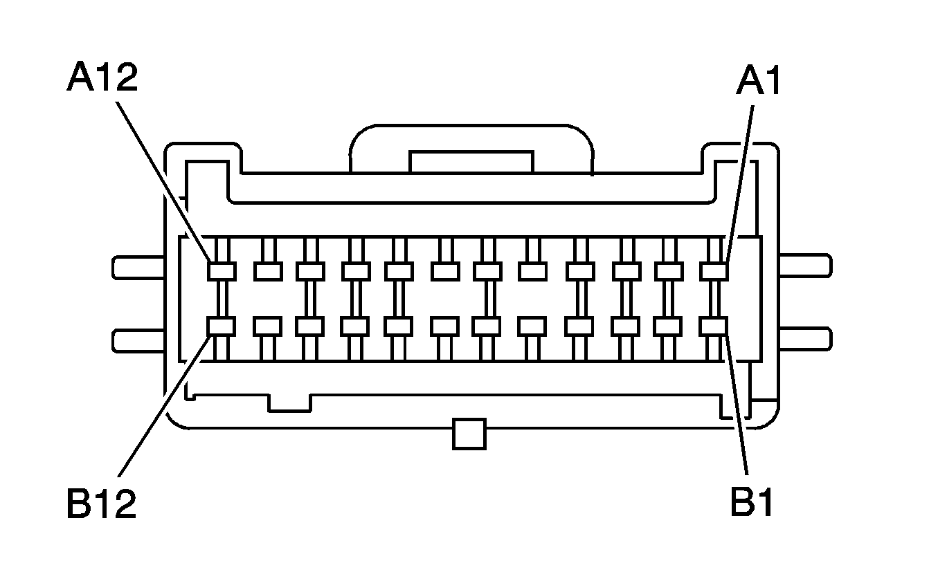
| ||||||||||||||
|---|---|---|---|---|---|---|---|---|---|---|---|---|---|---|---|
Connector Part Information |
| Connector Part Information |
| ||||||||||||
Pin | Wire Color | Circuit No. | Function | Pin | Wire Color | Circuit No. | Function | ||||||||
A1-A7 | -- | -- | Not Used | A1-A7 | -- | -- | Not Used | ||||||||
A8 | BN | 199 | Left Rear Speaker Output (+) | A8 | BN | 199 | Left Rear Speaker Output (+) | ||||||||
A9 | YE | 116 | Left Rear Speaker Output (-) | A9 | YE | 116 | Left Rear Speaker Output (-) | ||||||||
A10 | GN | 117 | Right Front Speaker Output (-) | A10 | GN | 117 | Right Front Speaker Output (-) | ||||||||
A11 | GN | 200 | Right Front Speaker Output (+) | A11 | GN | 200 | Right Front Speaker Output (+) | ||||||||
A12 | BK | 550 | Ground | A12 | BK | 550 | Ground | ||||||||
B1 | OG | 440 | Battery Positive Voltage | B1 | OG | 440 | Battery Positive Voltage | ||||||||
B2 | YE | 43 | Accessory Voltage | B2 | YE | 43 | Accessory Voltage | ||||||||
B3 | OG | 2140 | Battery Positive Voltage | B3 | OG | 2140 | Battery Positive Voltage | ||||||||
B4 | GY | 8 | Instrument Panel Lamp Supply Voltage | B4 | GY | 8 | Instrument Panel Lamp Supply Voltage | ||||||||
B5-B7 | -- | -- | Not Used | B5-B7 | -- | -- | Not Used | ||||||||
B8 | TN | 201 | Left Front Speaker Output (+) | B8 | TN | 201 | Left Front Speaker Output (+) | ||||||||
B9 | GY | 118 | Left Front Speaker Output (-) | B9 | GY | 118 | Left Front Speaker Output (-) | ||||||||
B10 | BLU | 115 | Right Rear Speaker Output (-) | B10 | BLU | 115 | Right Rear Speaker Output (-) | ||||||||
B11 | BLU | 46 | Right Rear Speaker Output (+) | B11 | BLU | 46 | Right Rear Speaker Output (+) | ||||||||
B12 | BN | 9 | Park Lamp Supply Voltage | B12 | BN | 9 | Park Lamp Supply Voltage | ||||||||
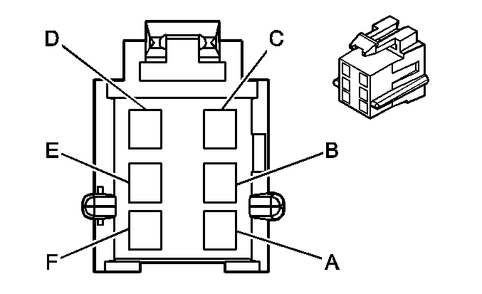
|
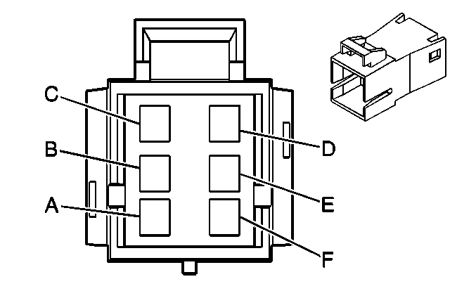
| ||||||||||||||
|---|---|---|---|---|---|---|---|---|---|---|---|---|---|---|---|
Connector Part Information |
| Connector Part Information |
| ||||||||||||
Pin | Wire Color | Circuit No. | Function | Pin | Wire Color | Circuit No. | Function | ||||||||
A | -- | -- | Not Used | A | GY | 8 | Not Used | ||||||||
B | OG | 2240 | Battery Positive Voltage | B | OG | 2240 | Battery Positive Voltage | ||||||||
C | BK | 350 | Ground | C | BK | 350 | Ground | ||||||||
BK | 550 | Ground | BK | 550 | Ground | ||||||||||
D | OG | 1740 | Battery Positive Voltage | D | OG | 1740 | Battery Positive Voltage | ||||||||
E-F | -- | -- | Not Used | E-F | -- | -- | Not Used | ||||||||
|

| ||||||||||||||
|---|---|---|---|---|---|---|---|---|---|---|---|---|---|---|---|
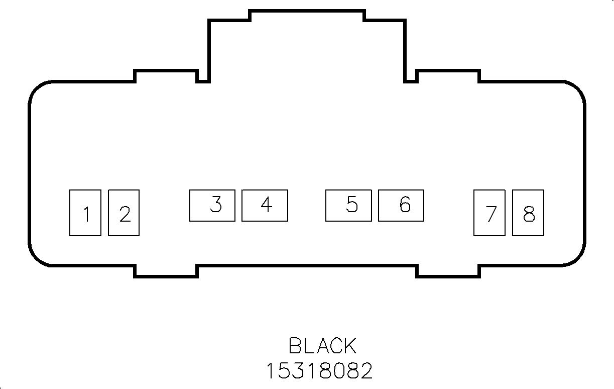
Connector Part Information |
| Connector Part Information |
| ||||||||||||
Pin | Wire Color | Circuit No. | Function | Pin | Wire Color | Circuit No. | Function | ||||||||
1 | PK | 1501 | Driver Heated Seat High/Low Signal | 1 | PK | 1501 | Driver Heated Seat High/Low Signal | ||||||||
2 | YE | 182 | Heated Seat Control Module Inhibit Signal | 2 | YE | 182 | Heated Seat Control Module Inhibit Signal | ||||||||
3 | BN | 141 | Ignition 3 Voltage | 3 | BN | 141 | Ignition 3 Voltage | ||||||||
4 | BK | 450 | Ground | 4 | BK | 450 | Ground | ||||||||
5 | OG | 640 | Batery Positive Voltage | 5 | OG | 640 | Batery Positive Voltage | ||||||||
6 | BK | 450 | Ground | 6 | BK | 450 | Ground | ||||||||
7 | D- BLU | 1363 | Seat Belt Switch - Left - Low Reference | 7 | D- BLU | 1363 | Seat Belt Switch - Left - Low Reference | ||||||||
8 | BK/WH | 238 | Seat Belt Switch - Left | 8 | BK/WH | 238 | Seat Belt Switch - Left | ||||||||

|

| ||||||||||||||
|---|---|---|---|---|---|---|---|---|---|---|---|---|---|---|---|
Connector Part Information |
| Connector Part Information |
| ||||||||||||
Pin | Wire Color | Circuit No. | Function | Pin | Wire Color | Circuit No. | Function | ||||||||
1 | PK/BK | 1503 | Passenger Heated Seat High/Low Signal | 1 | PK/BK | 1503 | Passenger Heated Seat High/Low Signal | ||||||||
2 | L-GN | 559 | Heated Seat Control Module Inhibit Signal | 2 | L-GN | 559 | Heated Seat Control Module Inhibit Signal | ||||||||
3 | BN | 141 | Ignition 3 Voltage | 3 | BN | 141 | Ignition 3 Voltage | ||||||||
4 | BK | 450 | Ground | 4 | BK | 450 | Ground | ||||||||
5-8 | -- | -- | Not Used | 5-8 | -- | -- | Not Used | ||||||||
|
| ||||||||||||||
|---|---|---|---|---|---|---|---|---|---|---|---|---|---|---|---|
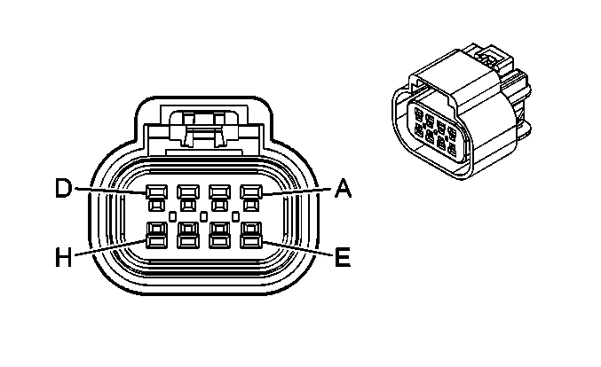
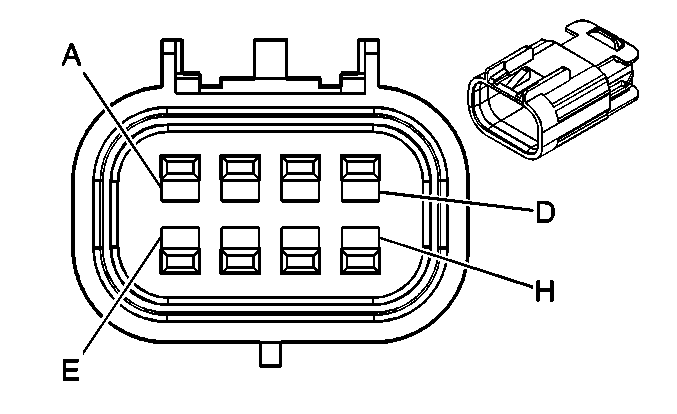
Connector Part Information |
| Connector Part Information |
| ||||||||||||
Pin | Wire Color | Circuit No. | Function | Pin | Wire Color | Circuit No. | Function | ||||||||
A | GY | 120 | Fuel Pump Supply Voltage | A | GY | 120 | Fuel Pump Supply Voltage | ||||||||
B | BK | 650 | Ground | B | BK | 650 | Ground | ||||||||
C | BK | 2759 | Low Reference | C | BK | 2759 | Low Reference | ||||||||
D | -- | -- | Not Used | D | -- | -- | Not Used | ||||||||
E | D- GN | 890 | Fuel Tank Pressure Sensor Signal | E | D- GN | 890 | Fuel Tank Pressure Sensor Signal | ||||||||
F | GY | 2709 | 5 Volt Reference | F | GY | 2709 | 5 Volt Reference | ||||||||
G | BK | 2759 | Low Reference | G | BK | 2759 | Low Reference | ||||||||
H | PU | 30 | Fuel Level Sensor Signal | H | PU | 30 | Fuel Level Sensor Signal | ||||||||
|
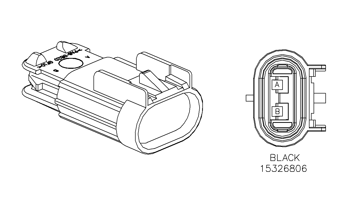
| ||||||||||||||
|---|---|---|---|---|---|---|---|---|---|---|---|---|---|---|---|
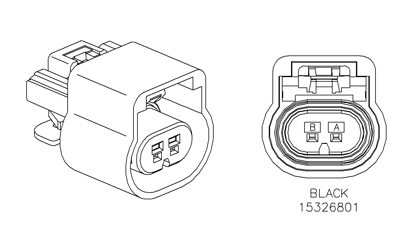
Connector Part Information |
| Connector Part Information |
| ||||||||||||
Pin | Wire Color | Circuit No. | Function | Pin | Wire Color | Circuit No. | Function | ||||||||
A | OG | 2740 | Battery Positive Voltage | A | OG | 2740 | Battery Positive Voltage | ||||||||
B | WH | 1310 | EVAP Canister Vent Solenoid Control | B | WH | 1310 | EVAP Canister Vent Solenoid Control | ||||||||
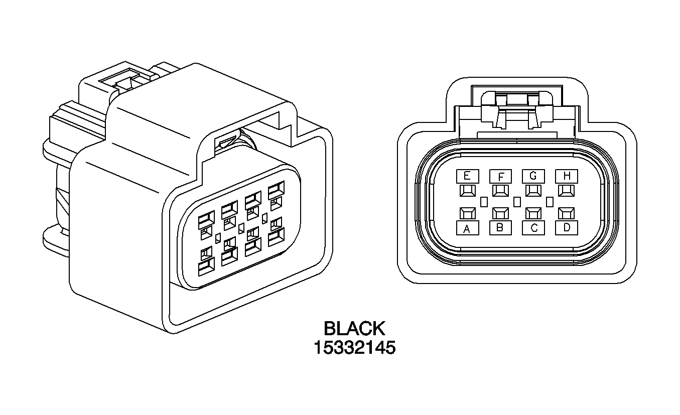
|
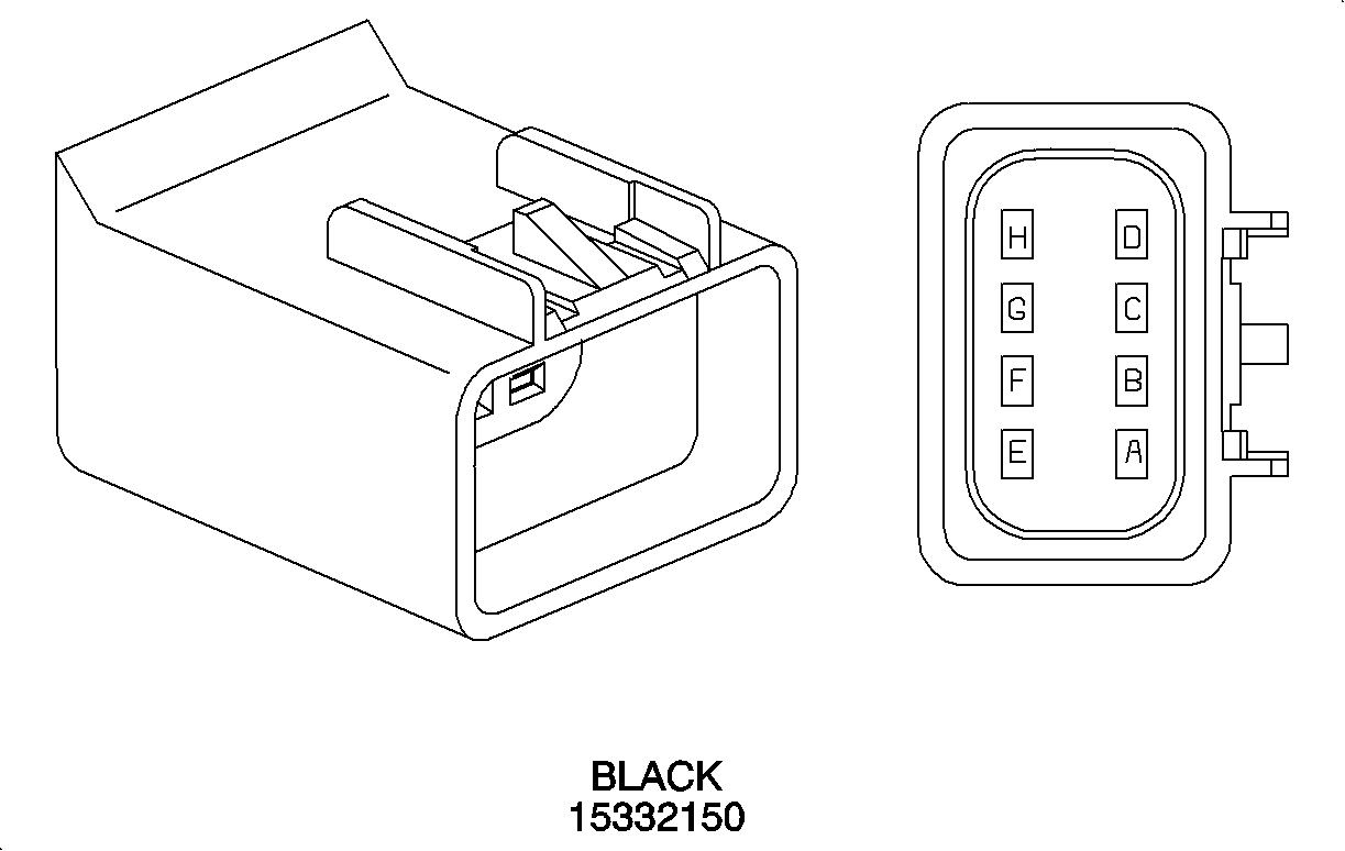
| ||||||||||||||
|---|---|---|---|---|---|---|---|---|---|---|---|---|---|---|---|
Connector Part Information |
| Connector Part Information |
| ||||||||||||
Pin | Wire Color | Circuit No. | Function | Pin | Wire Color | Circuit No. | Function | ||||||||
A | D-GN/WH | 368 | Right Audio Signal | A | D-GN/WH | 368 | Right Audio Signal | ||||||||
B | -- | 814 | Drain Wire | B | Bare | 814 | Drain Wire | ||||||||
C | BK/WH | 372 | Audio Common | C | BK/WH | 372 | Audio Common | ||||||||
D | BN/WH | 367 | Left Audio Signal | D | BN/WH | 367 | Left Audio Signal | ||||||||
E | D-BU | 601 | Data Clock Signal | E | D-BU | 601 | Data Clock Signal | ||||||||
F | BK | 650 | Ground | F | BK | 650 | Ground | ||||||||
G | OG | 1340 | Battery Positive Voltage | G | OG | 1340 | Battery Positive Voltage | ||||||||
H | PU | 1807 | Class 2 Serial Data | H | PU | 1807 | Class 2 Serial Data | ||||||||
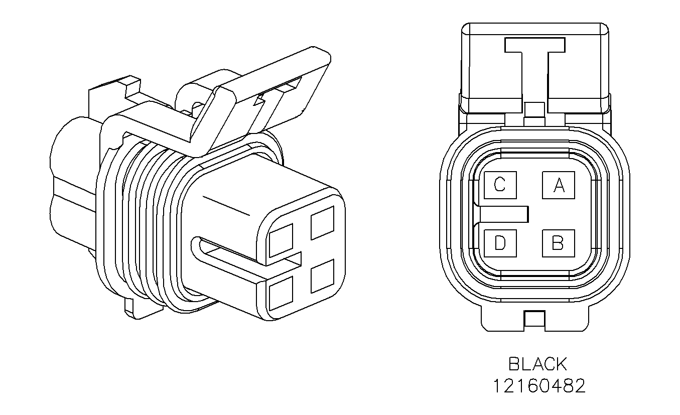
|
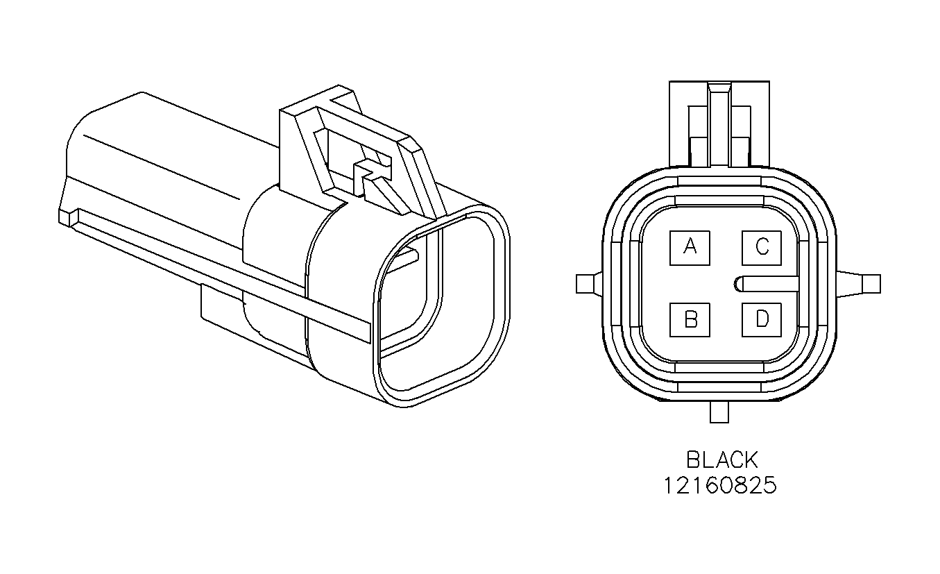
| ||||||||||||||
|---|---|---|---|---|---|---|---|---|---|---|---|---|---|---|---|
Connector Part Information |
| Connector Part Information |
| ||||||||||||
Pin | Wire Color | Circuit No. | Function | Pin | Wire Color | Circuit No. | Function | ||||||||
A | BK | 884 | Left Rear Wheel Speed Sensor | A | BK | 884 | Left Body to I/P Inline | ||||||||
B | BN | 882 | Right Rear Wheel Speed Sensor | B | BN | 882 | Left Body to I/P Inline | ||||||||
C | WH | 883 | Right Rear Wheel Speed Sensor | C | WH | 883 | Left Body to I/P Inline | ||||||||
D | RD | 885 | Left Rear Wheel Speed Sensor | D | RD | 885 | Left Body to I/P Inline | ||||||||
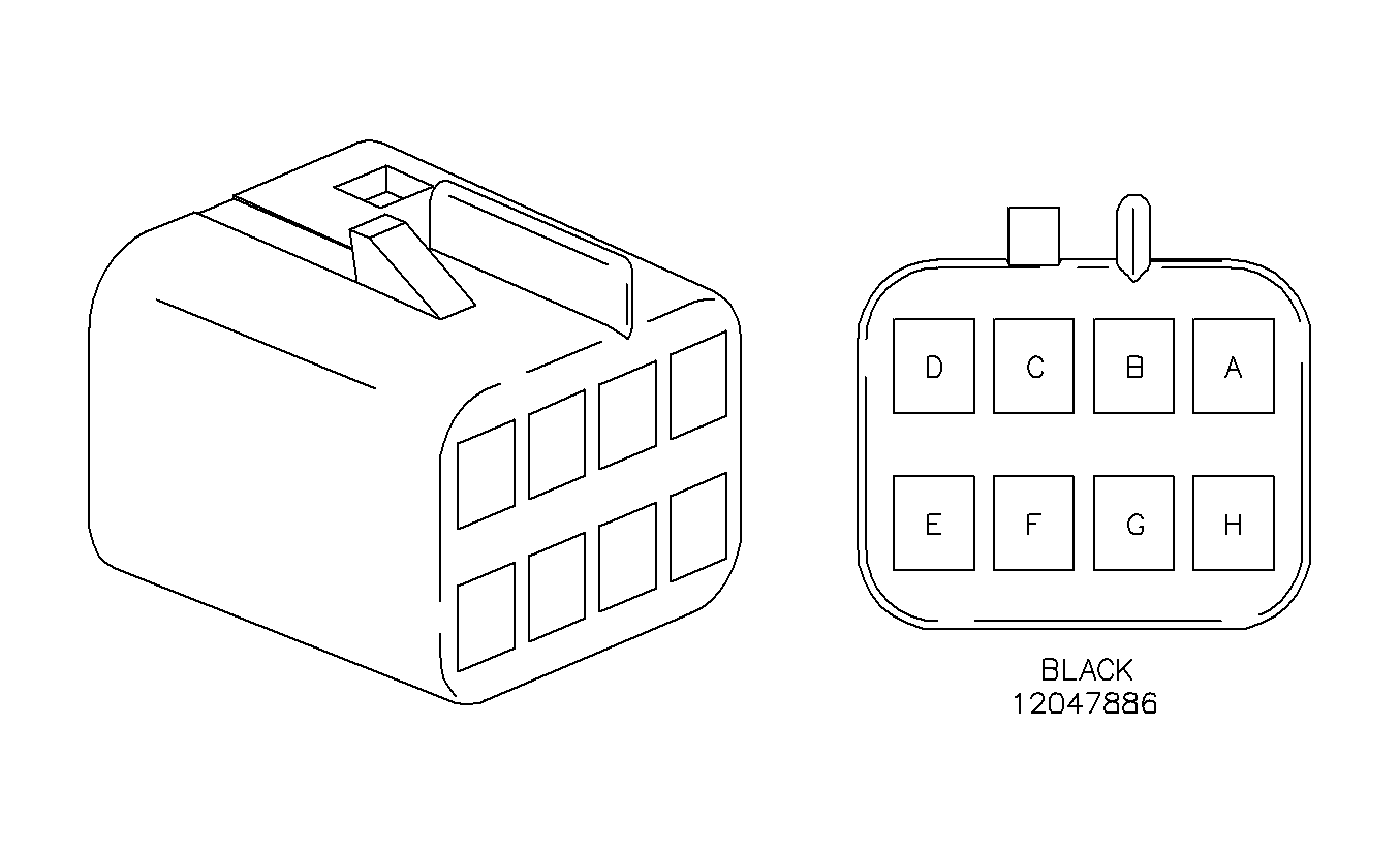
|
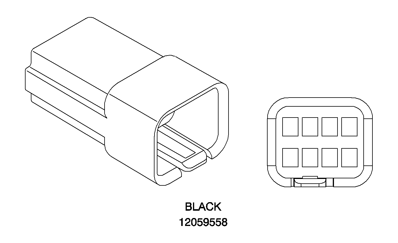
| ||||||||||||||
|---|---|---|---|---|---|---|---|---|---|---|---|---|---|---|---|
Connector Part Information |
| Connector Part Information |
| ||||||||||||
Pin | Wire Color | Circuit No. | Function | Pin | Wire Color | Circuit No. | Function | ||||||||
A | WH | 393 | Rear Window Wiper Motor Control | A | WH | 393 | Rear Window Wiper Motor Control | ||||||||
B | YE | 143 | Accessory Voltage | B | YE | 143 | Accessory Voltage | ||||||||
C | BK | 650 | Ground | C | BK | 650 | Ground | ||||||||
D | GY | 382 | Trunk Release Enable Relay Switch Supply Voltage | D | GY | 382 | Trunk Release Enable Relay Switch Supply Voltage | ||||||||
E | RD/BK | 744 | Rear Compartment Lid Adjar Switch Signal | E | RD/BK | 744 | Rear Compartment Lid Adjar Switch Signal | ||||||||
F | L-BU | 20 | Stop Lamp Supply Voltage | F | L-BU | 20 | Stop Lamp Supply Voltage | ||||||||
G | BK | 305 | Trunk Key Switch Signal | G | BK | 305 | Trunk Key Switch Signal | ||||||||
H | OG | 340 | Battery Positive Voltage | H | OG | 340 | Battery Positive Voltage | ||||||||
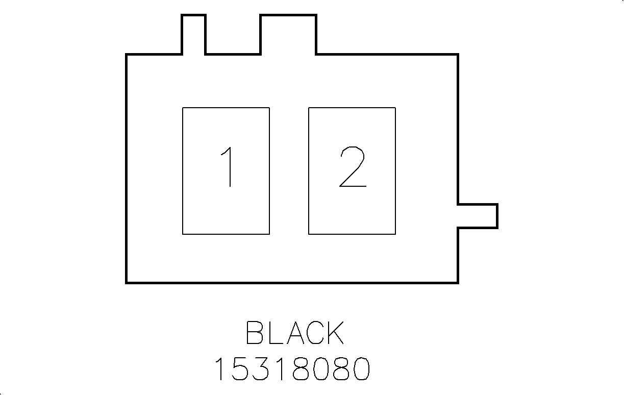
|
| ||||||||||||||
|---|---|---|---|---|---|---|---|---|---|---|---|---|---|---|---|
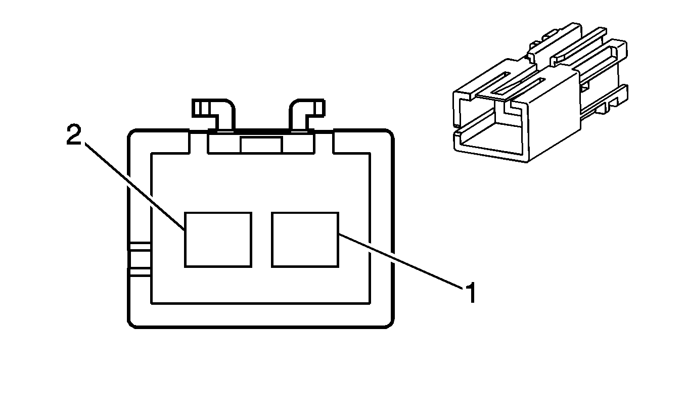
Connector Part Information |
| Connector Part Information |
| ||||||||||||
Pin | Wire Color | Circuit No. | Function | Pin | Wire Color | Circuit No. | Function | ||||||||
1 | BN | 9 | Park Lamp Supply Voltage | 1 | BN | 9 | Park Lamp Supply Voltage | ||||||||
2 | PU | 293 | Rear Defog Element Supply Voltage | 2 | PU | 293 | Rear Defog Element Supply Voltage | ||||||||
|
| ||||||||||||||
|---|---|---|---|---|---|---|---|---|---|---|---|---|---|---|---|
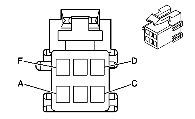
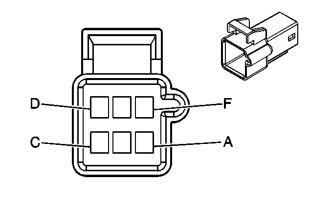
Connector Part Information |
| Connector Part Information |
| ||||||||||||
Pin | Wire Color | Circuit No. | Function | Pin | Wire Color | Circuit No. | Function | ||||||||
A | BN | 9 | Park Lamp Supply Voltage | A | BN | 9 | Park Lamp Supply Voltage | ||||||||
B | L-BU | 20 | Stop Lamp Supply Voltage | B | L-BU | 20 | Stop Lamp Supply Voltage | ||||||||
C | D-BU | 15 | Right Turn Signal Lamps Supply Voltage | C | D-BU | 15 | Right Turn Signal Lamps Supply Voltage | ||||||||
D | BK | 650 | Ground | D | BK | 650 | Ground | ||||||||
E | L-GRN | 24 | Backup Lamp Supply Voltage | E | L-GRN | 24 | Backup Lamp Supply Voltage | ||||||||
F | -- | -- | Not Used | F | -- | -- | Not Used | ||||||||

|

| ||||||||||||||
|---|---|---|---|---|---|---|---|---|---|---|---|---|---|---|---|
Connector Part Information |
| Connector Part Information |
| ||||||||||||
Pin | Wire Color | Circuit No. | Function | Pin | Wire Color | Circuit No. | Function | ||||||||
A | BN | 9 | Park Lamp Supply Voltage | A | BN | 9 | Park Lamp Supply Voltage | ||||||||
B | L-BU | 20 | Stop Lamp Supply Voltage | B | L-BU | 20 | Stop Lamp Supply Voltage | ||||||||
C | D-BU | 14 | Left Turn Signal Lamps Supply Voltage | C | D-BU | 14 | Left Turn Signal Lamps Supply Voltage | ||||||||
D | BK | 650 | Ground | D | BK | 650 | Ground | ||||||||
E | L-GRN | 24 | Backup Lamp Supply Voltage | E | L-GRN | 24 | Backup Lamp Supply Voltage | ||||||||
F | -- | -- | Not Used | F | -- | -- | Not Used | ||||||||

|

| ||||||||||||||
|---|---|---|---|---|---|---|---|---|---|---|---|---|---|---|---|
Connector Part Information |
| Connector Part Information |
| ||||||||||||
Pin | Wire Color | Circuit No. | Function | Pin | Wire Color | Circuit No. | Function | ||||||||
A | L-GN | 89 | Driver Mirror Motor Down Control | A | L-GN | 89 | Driver Mirror Motor Down Control | ||||||||
B | WH | 81 | Driver Mirror Motor Right Control | B | WH | 81 | Driver Mirror Motor Right Control | ||||||||
C | OG/BK | 781 | Driver Door Lock Switch Unlock Signal | C | RD/BK | 780 | Driver Door Lock Switch Unlock Signal | ||||||||
D | RD/BK | 780 | Driver Door Lock Switch Lock Signal | D | OG/BK | 781 | Driver Door Lock Switch Lock Signal | ||||||||
E | OG | 340 | Battery Positive Voltage | E | OG | 340 | Battery Positive Voltage | ||||||||
F | L-BU | 82 | Driver Mirror Motor Left Control | F | L-BU | 82 | Driver Mirror Motor Left Control | ||||||||
G | L-BU | 82 | Driver Mirror Motor Left Control | G | L-BU | 82 | Driver Mirror Motor Left Control | ||||||||
H | -- | -- | Not Used | H | -- | -- | Not Used | ||||||||
|
| ||||||||||||||
|---|---|---|---|---|---|---|---|---|---|---|---|---|---|---|---|
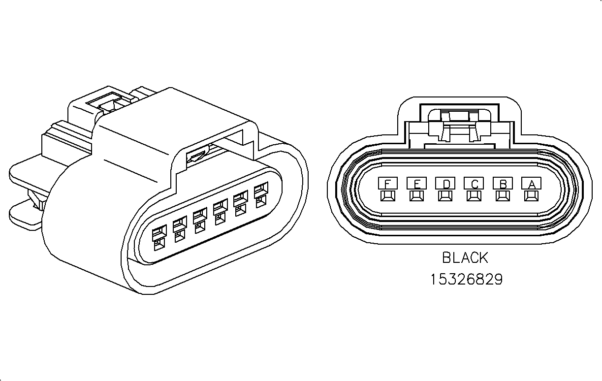
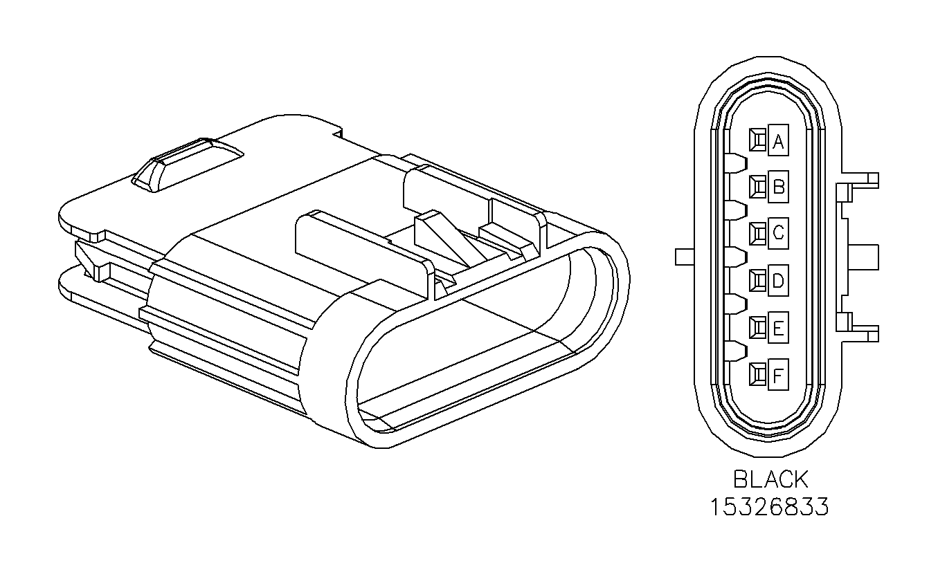
Connector Part Information |
| Connector Part Information |
| ||||||||||||
Pin | Wire Color | Circuit No. | Function | Pin | Wire Color | Circuit No. | Function | ||||||||
A | GY | 118 | Left Front Speaker Output (-) | A | GY | 118 | Left Front Speaker Output (-) | ||||||||
B | TN | 201 | Left Front Speaker Output (+) | B | TN | 201 | Left Front Speaker Output (+) | ||||||||
C | BK | 550 | Ground | C | BK | 550 | Ground | ||||||||
D | OG | 267 | Heated Mirror/Rear Defog Relay Coil Supply Voltage | D | OG | 267 | Heated Mirror/Rear Defog Relay Coil Supply Voltage | ||||||||
E | BK | 550 | Ground | E | BK | 550 | Ground | ||||||||
F | YE | 743 | Accessory Voltage | F | YE | 743 | Accessory Voltage | ||||||||
|
| ||||||||||||||
|---|---|---|---|---|---|---|---|---|---|---|---|---|---|---|---|
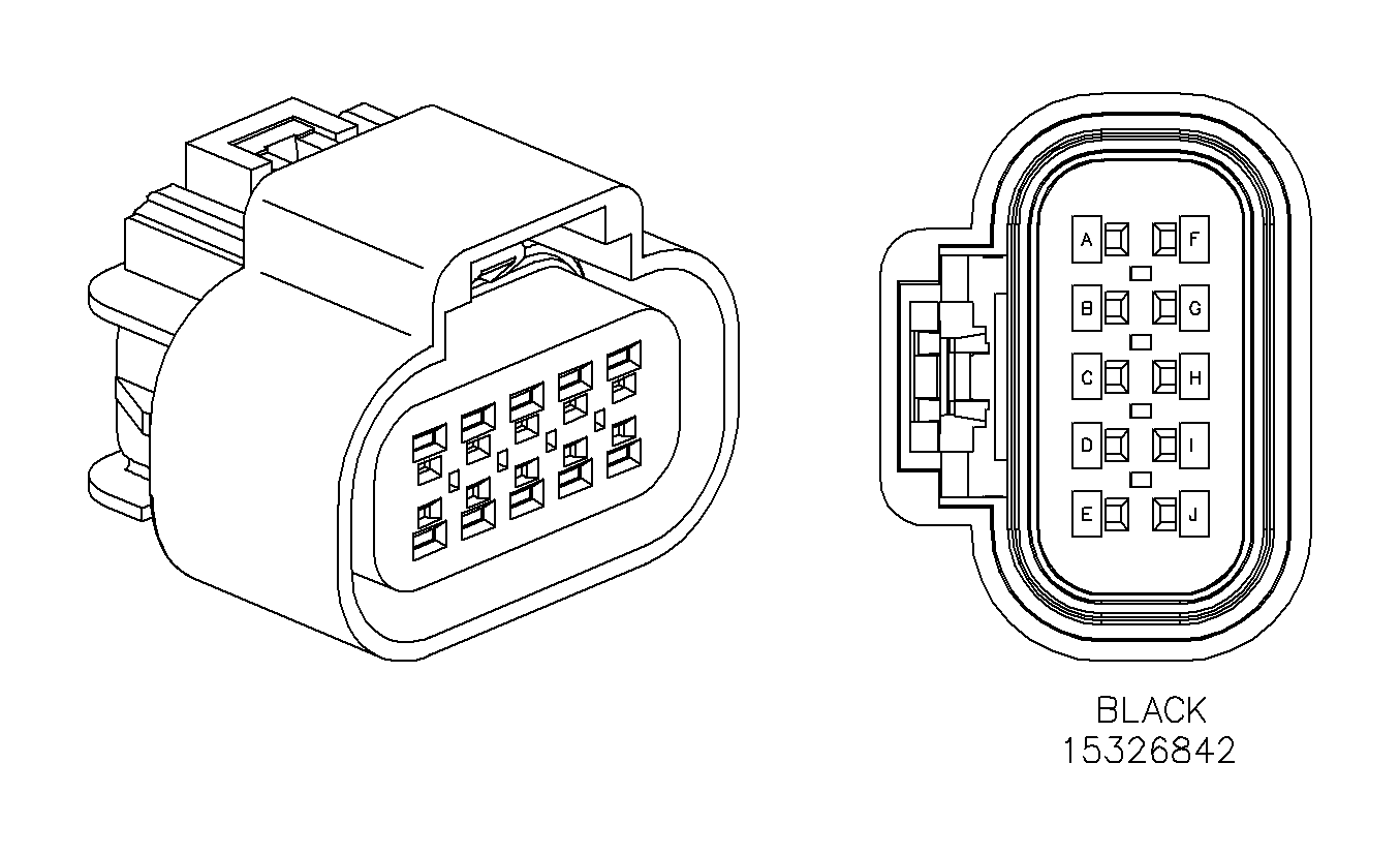
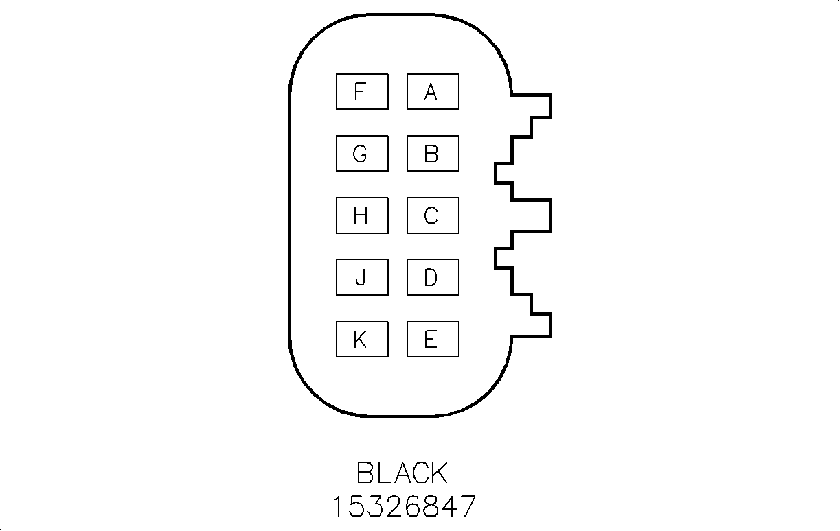
Connector Part Information |
| Connector Part Information |
| ||||||||||||
Pin | Wire Color | Circuit No. | Function | Pin | Wire Color | Circuit No. | Function | ||||||||
A | D- GN | 117 | Right Front Speaker Output (-) | A | D- GN | 117 | Right Front Speaker Output (-) | ||||||||
B | L-GN | 200 | Right Front Speaker Output (+) | B | L-GN | 200 | Right Front Speaker Output (+) | ||||||||
C | BK | 450 | Ground | C | BK | 450 | Ground | ||||||||
D | OG | 267 | Heated Mirror/Rear Defog Relay Coil Supply Voltage | D | OG | 267 | Heated Mirror/Rear Defog Relay Coil Supply Voltage | ||||||||
E | L-GN | 89 | Mirror Motor Down Control | E | L-GN | 89 | Mirror Motor Down Control | ||||||||
F | WH | 81 | Driver Mirror Motor Right Control | F | WH | 81 | Driver Mirror Motor Right Control | ||||||||
G | RD/BK | 780 | Driver Door Lock Switch Lock Signal | G | RD/BK | 780 | Driver Door Lock Switch Lock Signal | ||||||||
H | OG/BK | 781 | Driver Door Lock Switch Unlock Signal | H | OG/BK | 781 | Driver Door Lock Switch Unlock Signal | ||||||||
J | OG | 340 | Battery Positive Voltage | J | OG | 340 | Battery Positive Voltage | ||||||||
K | L-BU | 82 | Driver Mirror Motor Left Control | K | L-BU | 82 | Driver Mirror Motor Left Control | ||||||||
|
| ||||||||||||||
|---|---|---|---|---|---|---|---|---|---|---|---|---|---|---|---|
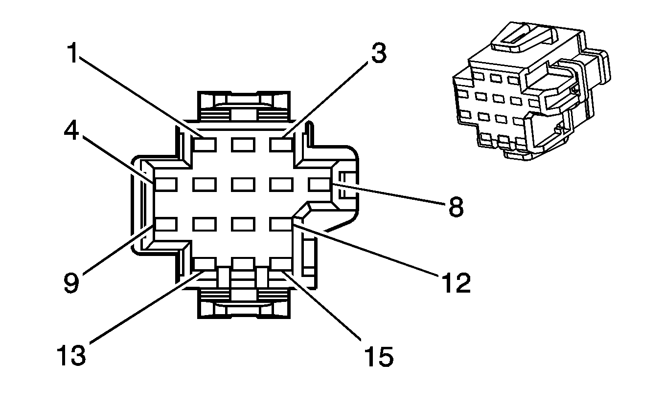
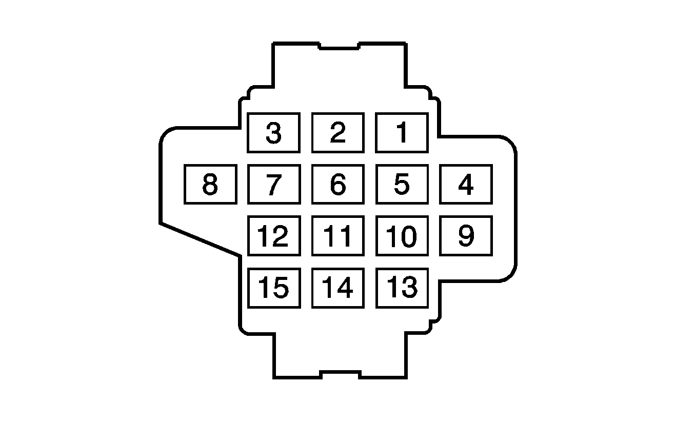
Connector Part Information |
| Connector Part Information |
| ||||||||||||
Pin | Wire Color | Circuit No. | Function | Pin | Wire Color | Circuit No. | Function | ||||||||
1-2 | -- | -- | Not Used | 1-2 | -- | -- | Not Used | ||||||||
3 | GY | 295 | Door Lock Actuator Lock Control | 3 | GY | 295 | Door Lock Actuator Lock Control | ||||||||
4 | PU | 169 | Power Window Master Switch Left Rear Down Signal | 4 | PU | 169 | Power Window Master Switch Left Rear Down Signal | ||||||||
5 | D-GN | 168 | Power Window Master Switch Left Rear Up Signal | 5 | D-GN | 168 | Power Window Master Switch Left Rear Up Signal | ||||||||
6 | TN | 294 | Door Lock Actuator Unlock Control | 6 | TN | 294 | Door Lock Actuator Unlock Control | ||||||||
7-9 | -- | -- | Not Used | 7-9 | -- | -- | Not Used | ||||||||
10 | D-BU | 1307 | Power Window Master Switch Lockout Control | 10 | D-BU | 1307 | Power Window Master Switch Lockout Control | ||||||||
11 | L-BU/BK | 747 | Left Rear Door Ajar Switch Signal | 11 | L-BU/BK | 747 | Left Rear Door Ajar Switch Signal | ||||||||
12 | YE | 116 | Left Rear Speaker Output (-) | 12 | YE | 116 | Left Rear Speaker Output (-) | ||||||||
13 | WH | 199 | Left Rear Speaker Output (+) | 13 | WH | 199 | Left Rear Speaker Output (+) | ||||||||
14 | -- | -- | Not Used | 14 | -- | -- | Not Used | ||||||||
15 | OG | 1732 | Courtesy Lamps Supply Voltage | 15 | OG | 1732 | Courtesy Lamps Supply Voltage | ||||||||

|

| ||||||||||||||
|---|---|---|---|---|---|---|---|---|---|---|---|---|---|---|---|
Connector Part Information |
| Connector Part Information |
| ||||||||||||
Pin | Wire Color | Circuit No. | Function | Pin | Wire Color | Circuit No. | Function | ||||||||
1-2 | -- | -- | Not Used | 1-2 | -- | -- | Not Used | ||||||||
3 | GY | 295 | Door Lock Actuator Lock Control | 3 | GY | 295 | Door Lock Actuator Lock Control | ||||||||
4 | PU | 171 | Power Window Master Switch Right Rear Down Signal | 4 | PU | 171 | Power Window Master Switch Right Rear Down Signal | ||||||||
5 | L-GN | 170 | Power Window Master Switch Right Rear Up Signal | 5 | L-GN | 170 | Power Window Master Switch Right Rear Up Signal | ||||||||
6 | TN | 294 | Door Lock Actuator Unlock Control | 6 | TN | 294 | Door Lock Actuator Unlock Control | ||||||||
7-9 | -- | -- | Not Used | 7-9 | -- | -- | Not Used | ||||||||
10 | D-BU | 1307 | Power Window Master Switch Lockout Control | 10 | D-BU | 1307 | Power Window Master Switch Lockout Control | ||||||||
11 | L-GN/BK | 748 | Right Rear Door Ajar Switch Signal | 11 | L-GN/BK | 748 | Right Rear Door Ajar Switch Signal | ||||||||
12 | L-BU | 115 | Right Rear Speaker Output (-) | 12 | L-BU | 115 | Right Rear Speaker Output (-) | ||||||||
13 | D-BU | 46 | Right Rear Speaker Output (+) | 13 | D-BU | 46 | Right Rear Speaker Output (+) | ||||||||
14 | -- | -- | Not Used | 14 | -- | -- | Not Used | ||||||||
15 | OG | 1732 | Courtesy Lamps SuPUy Voltage | 15 | OG | 1732 | Courtesy Lamps SuPUy Voltage | ||||||||
