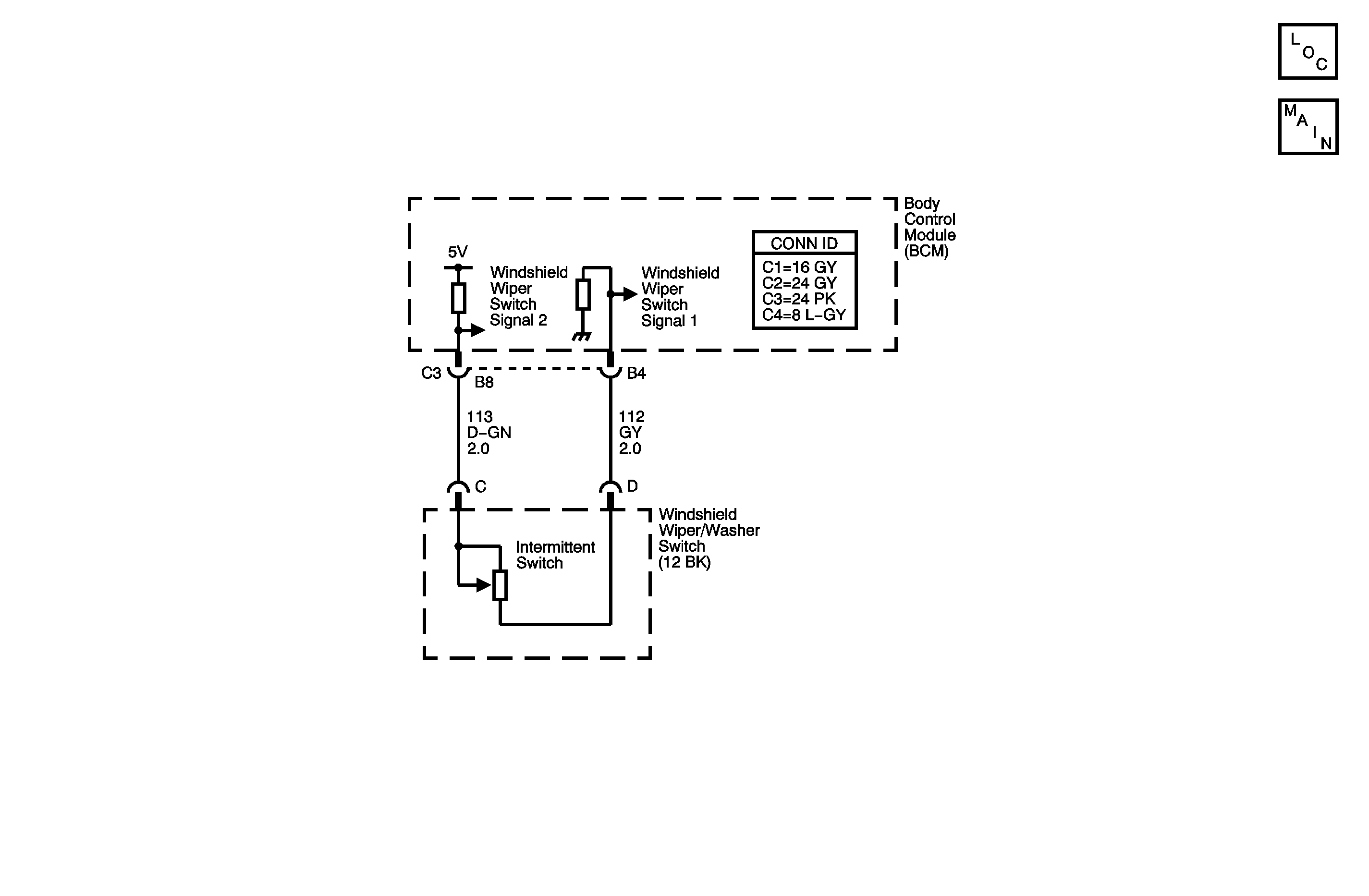
Circuit Description
The intermittent wiper delay switch is a voltage divider connected across the body control module (BCM) inputs circuit 113 and circuit 112. The wiper relay is energized by the BCM switching circuit 1445 to ground depending on delay switch position.
The intermittent wiper delay switch has three switch positions.
| • | Delay 1 (500 ohms resistance) |
| • | Delay 2 (1000 ohms resistance) |
| • | Delay 3 (2000 ohms resistance) |
Refer to Wiper/Washer System Description and Operation for the timing of each delay position
Conditions for Running the DTC
Ignition is in RUN or ACC position.
Conditions for Setting the DTC
| • | The windshield wiper switch signal circuit, circuit 113, is greater than 4.71 volts, open or shorted to voltage. |
| • | The low reference circuit, circuit 112, is open. |
Actions Taken When the DTC Sets
| • | No light will illuminate in I/P. |
| • | Cannot vary wiper speed. |
Conditions for Clearing the DTC
| • | A current DTC clears when the fault is no longer present. |
| • | A history DTC clears when the module ignition cycle counter reaches the reset threshold, without a repeat of the fault. |
Diagnostic Aids
| • | Inspect wiring harness for damage. Check for broken or chaffed insulation. |
| • | If fault is suspected to be intermittent, wiggling harness wiring may help in locating fault. |
| • | Check for poor connection at the BCM. Inspect harness connectors for backed out terminals, improper terminal mating, broken connector locks, improperly formed or damaged terminals and poor terminal-to-wire connection, terminal crimped over wire insulation and not conductors. |
Step | Action | Yes | No |
|---|---|---|---|
Schematic Reference: Wiper/Washer Schematics Connector End View Reference: Master Electrical Component List in Wiring Systems | |||
1 | Did you perform the Wiper/Washer Diagnostic System Check? | Go to Step 2 | |
2 |
Is the voltage greater than 4.71 volts? | Go to Step 3 | Go to Diagnostic Aids |
3 |
Is the voltage less than 4 volts? | Go to Step 4 | Go to Step 5 |
4 | Measure voltage on the windshield wiper switch signal circuit to ground. Is the voltage between 4-6 volts? | Go to Step 7 | Go to Step 8 |
5 | Is voltage between 4-6 volts? | Go to Step 6 | Go to Step 9 |
6 | Using a fused jumper, jumper the windshield wiper switch signal circuit to the low reference circuit at harness connector. Is the voltage less than 0.4 volts? | Go to Step 11 | Go to Step 10 |
7 | Test the low reference circuit for an open. Refer to Circuit Testing and Wiring Repairs in Wiring Systems. Did you find and correct the condition? | Go to Step 12 | Go to Step 10 |
8 | Test the windshield wiper switch signal circuit for an open. Refer to Circuit Testing and Wiring Repairs in Wiring Systems. Did you find and correct the condition? | Go to Step 12 | Go to Step 10 |
9 | Test the windshield wiper switch signal circuit for a short to voltage. Refer to Circuit Testing and Wiring Repairs in Wiring Systems. Did you find and correct the condition? | Go to Step 12 | Go to Step 10 |
10 |
Important: Perform the programming or setup procedure for the replaced control module if required. Replace the BCM. Refer to Body Control Module Replacement in Body Control System for applicable replacement procedure. Did you complete the replacement? | Go to Step 12 | -- |
11 | Replace the windshield wiper/washer switch. Refer to Turn Signal Multifunction Switch Replacement in Steering Wheel and Column. Did you complete the replacement? | Go to Step 12 | -- |
12 |
Does the DTC reset? | Go to Step 2 | System OK |
