For 1990-2009 cars only
Removal Procedure
- Disconnect the negative battery cable. Refer to Battery Negative Cable Disconnection and Connection in Engine Electrical.
- Raise the vehicle. Refer to Lifting and Jacking the Vehicle in General Information.
- Drain the coolant. Refer to Cooling System Draining and Filling in Engine Cooling.
- Lower the vehicle.
- Remove the heater inlet hose:
- Remove the heater outlet hose:
- Place the end of heater outlet hose in a container and apply low pressure 34 kPa (5 psi) shop air to the heater inlet hose to blow the coolant out of the heater core.
- Remove the right console extension.
- Remove the heater core pipe to heater core clamps.
- Gently pull the pipes forward to remove the pipes from the heater core end tank.
- Place absorbent rags under the heater core pipe joints to catch any residual coolant.
- Remove the heater core retaining strap screw.
- Remove the heater core retaining strap.
- Remove the heater core from the HVAC module.
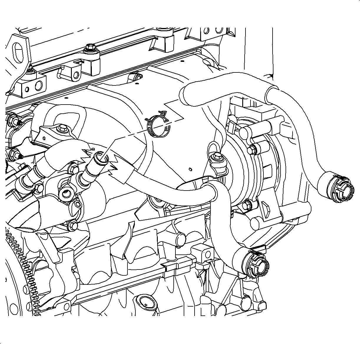
| • | From the auxiliary water pump outlet on L81 engines |
| • | From the thermostat outlet on L61 engines |
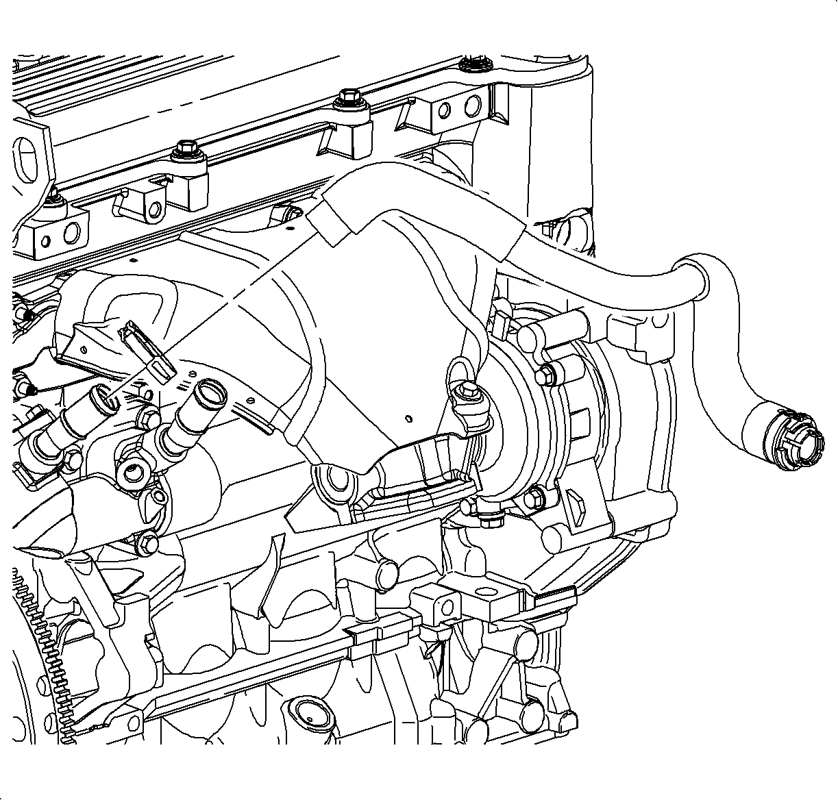
| • | From the head bridge on L81 engines |
| • | From the block inlet on L61 engines |
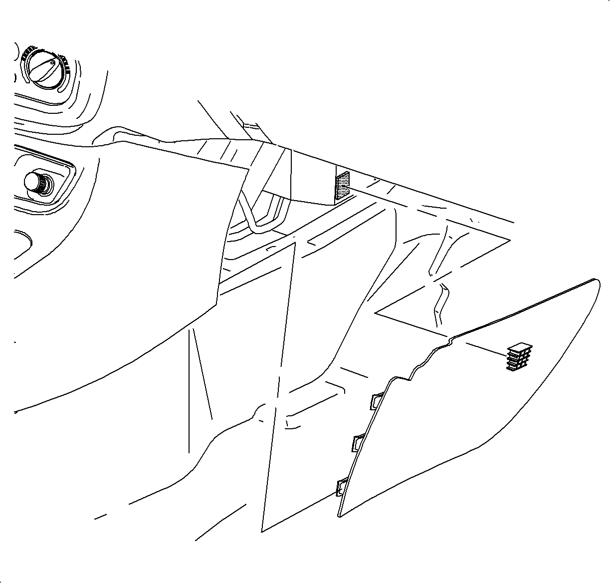
Caution: Refer to Moving Parts and Hot Surfaces Caution in the Preface section.
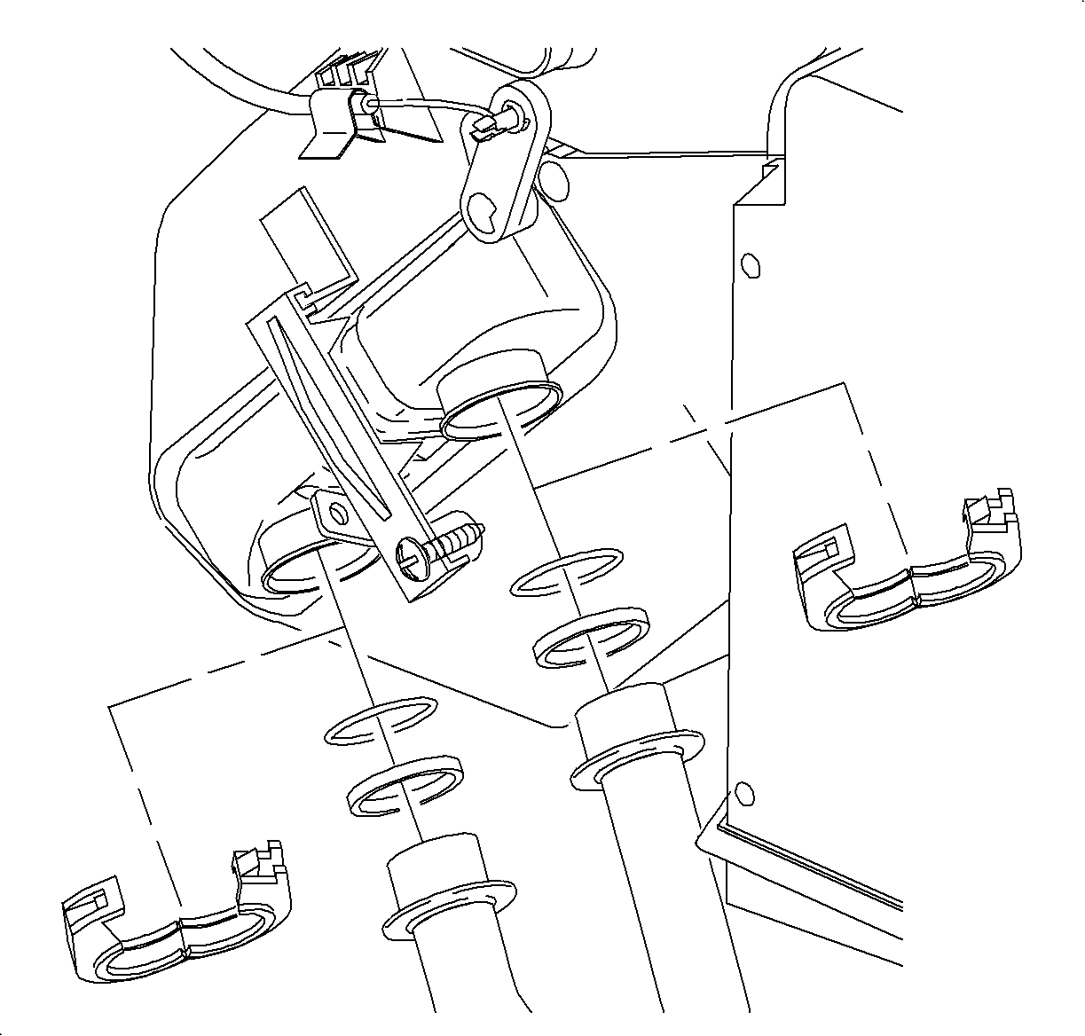
The clamps may need to be rotated to gain access to the clamp retaining tab.
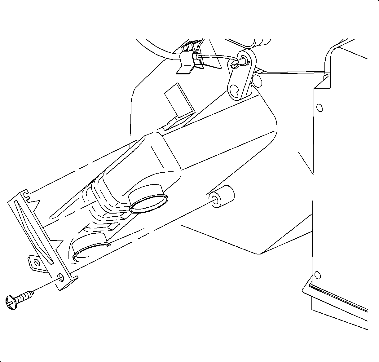
Important: Use care not to spill any residual coolant on carpet or seats.
Important: The center console forward edge may need to be pulled outward to allow for the core to be removed.
Installation Procedure
- Install the heater core into the HVAC module being careful not to damage the foam seals.
- Install the heater core retaining strap.
- Install the heater core retaining strap screw.
- Install the bushings and O-rings onto the heater core pipes.
- Install the heater pipes into the core and install the plastic clamps.
- Install the right console extension.
- Install the heater inlet hose to:
- Install the clamp at the 12 o'clock position.
- Install the heater outlet hose to:
- Connect the negative battery cable. Refer to Battery Negative Cable Disconnection and Connection in Engine Electrical.
- Fill the cooling system. Refer to Cooling System Draining and Filling in Engine Cooling.
- Rinse off any coolant that was spilled in the engine compartment.

Tighten
Tighten the screw to 1.9 N·m (9 lb in).

| • | The heater pipe clamps will only go on one way |
| • | The lower clamp hinge fits into the tab of the heater core retaining strap |

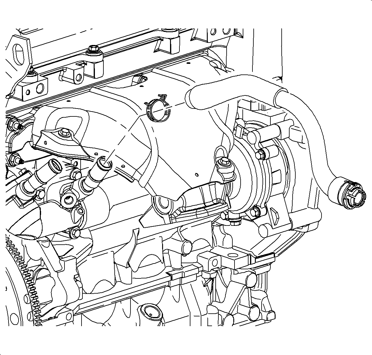
| • | The auxiliary water pump outlet on L81 |
| • | The thermostat outlet on L61 |
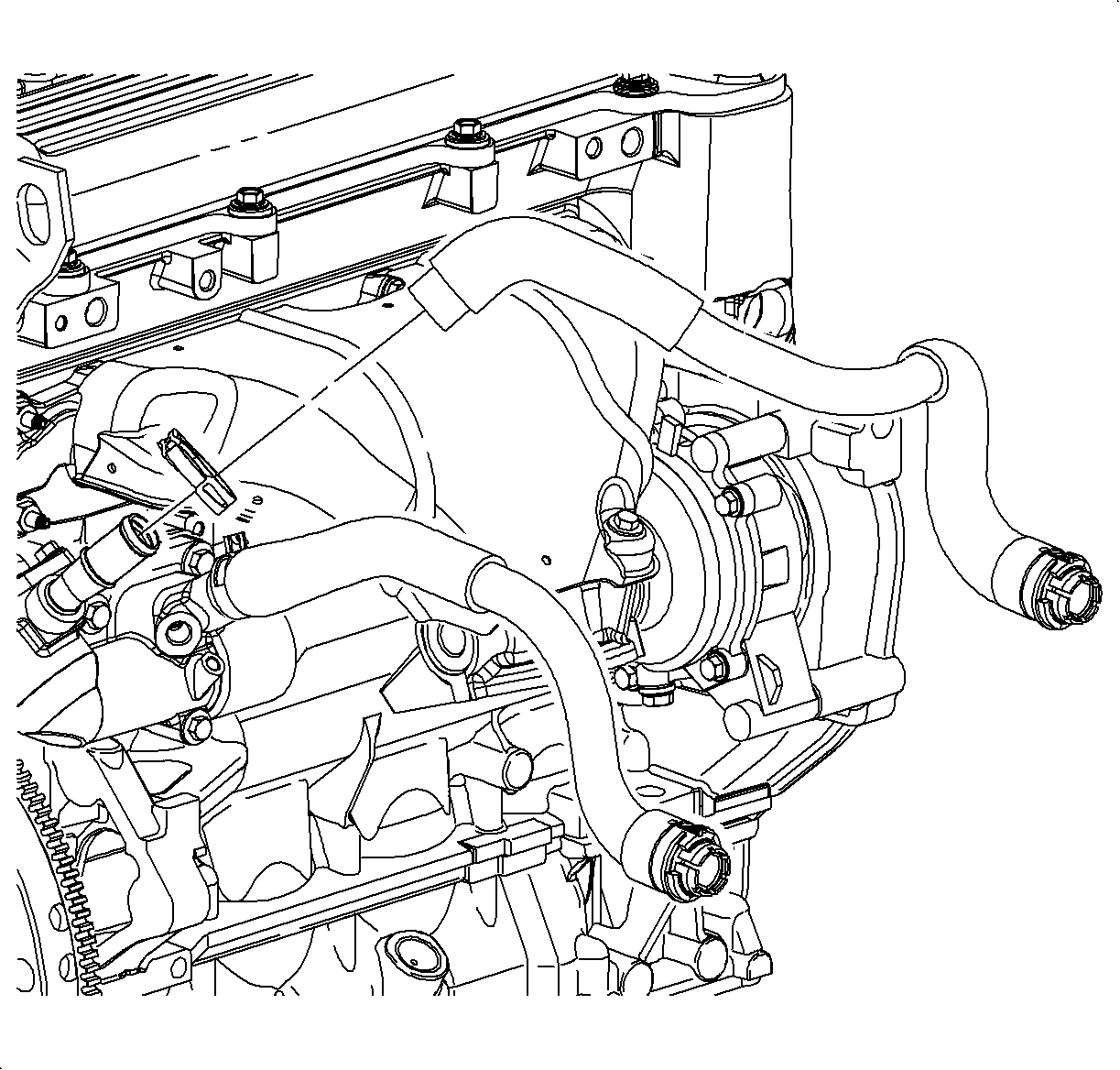
| • | The block inlet on L61. |
| • | Install the clamp at the 12 o'clock position. |
| • | Install the head bridge on L81. |
| • | Install the clamp at the 3 o'clock position. |
