For 1990-2009 cars only
Removal Procedure
- On vehicles equipped with ABS, the ABS controller must be removed. Refer to Electronic Brake Control Module Replacement in Antilock Brake System.
- Remove the brake pipes from the master cylinder.
- Disconnect the low brake fluid switch electrical connector.
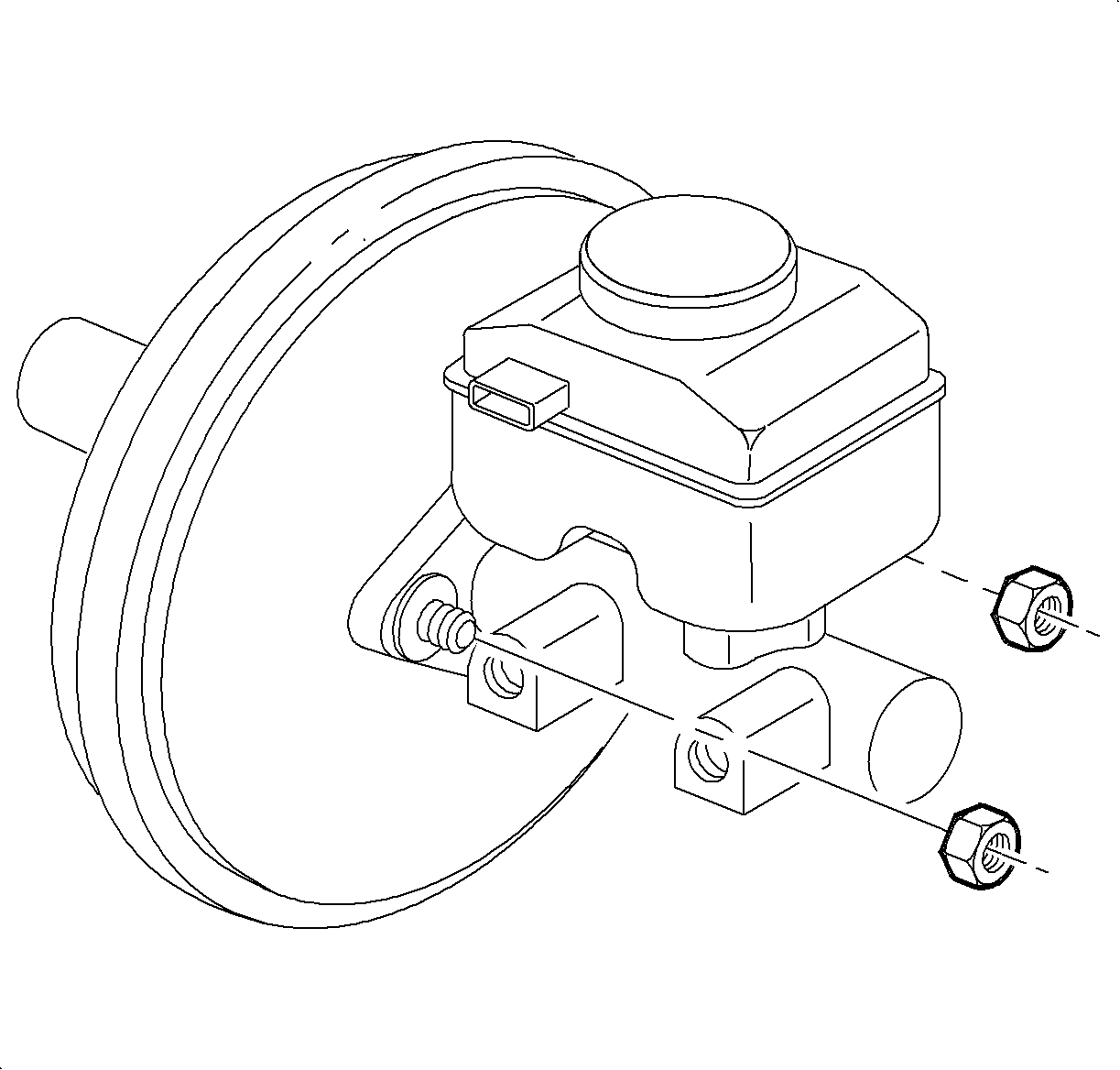
- Remove the master cylinder-to-brake booster nuts.
- Remove the master cylinder from the vehicle.
- Disconnect the vacuum check valve and the hose from the booster.
- Remove the left lower instrument panel (I/P) closeout panel, hush panel.
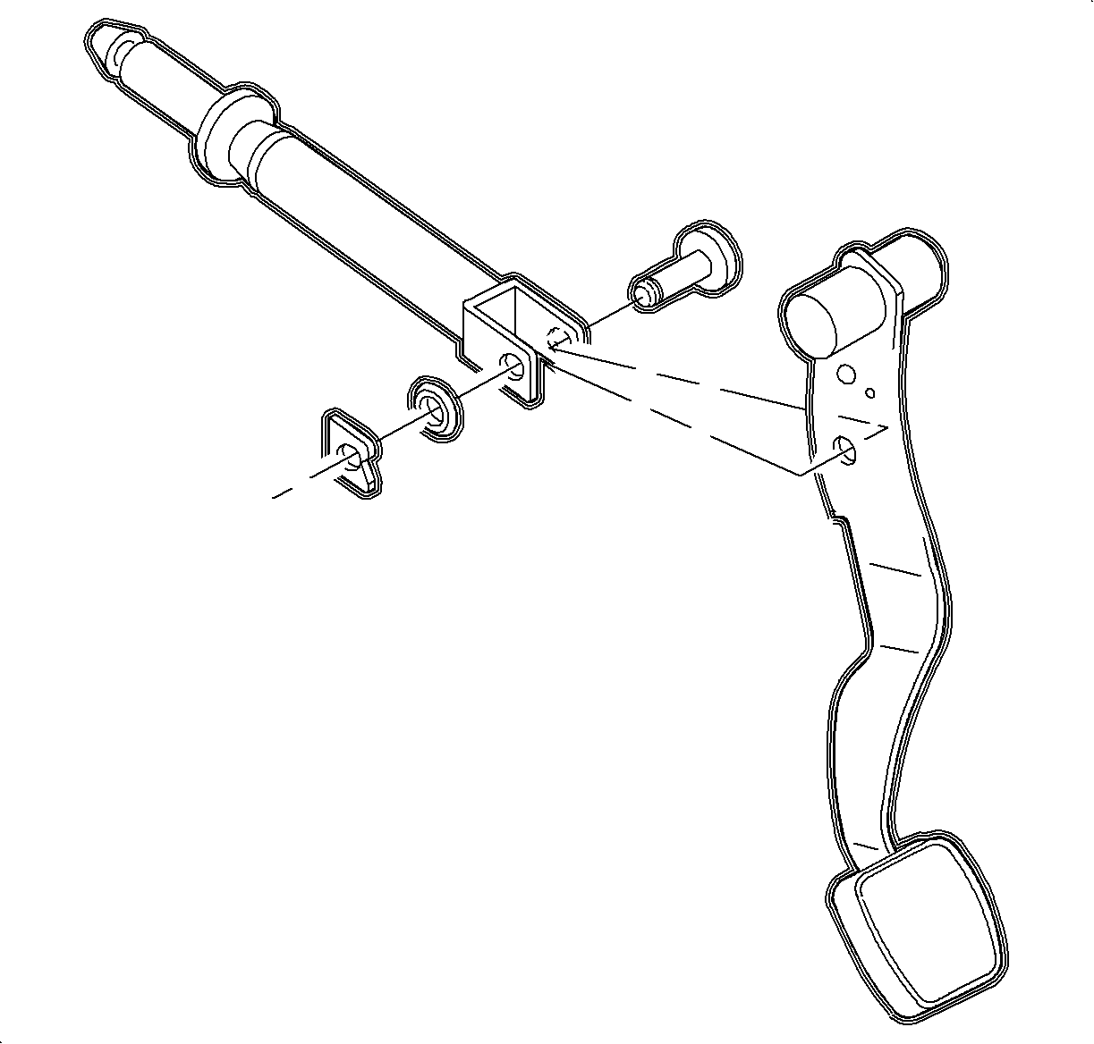
- Remove the booster push rod retainer and push rod from the brake pedal.
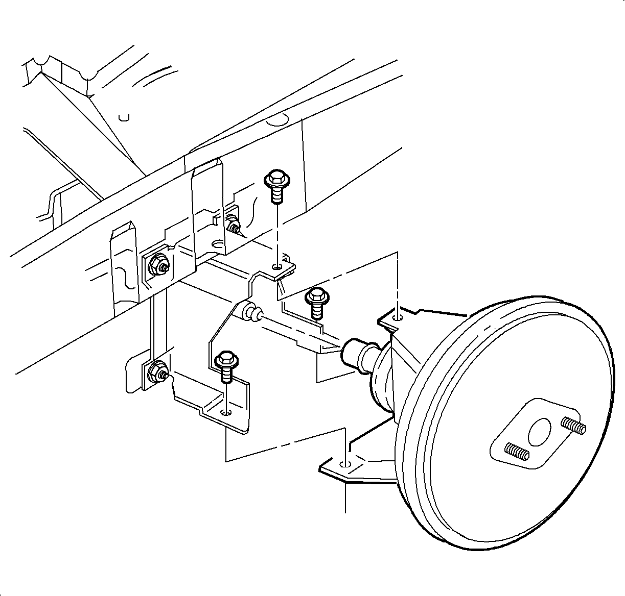
- Remove the brake booster-to-brake booster bracket attachment bolts.
- From under the hood, remove the booster.
Caution: Refer to Brake Fluid Irritant Caution in the Preface section.


| Important: The top bolt is accessed through the inside of the HVAC filter plenum. |
| 9.1. | Open the HVAC filter access panel. |
| 9.2. | Remove the rubber plug in the bottom of the cowling. |
| 9.3. | Remove the top brake booster-to-brake booster bracket bolt. |
Installation Procedure
- Position the booster in the vehicle. Install the brake booster-to-brake booster bracket attachment bolts.
- Install the rubber plug in the bottom of the cowling.
- Close and secure the HVAC access panel.
- Install the booster push rod onto brake pedal pushrod, pin with the retainer.
- Install the lower left I/P closeout panel, hush panel.
- Connect the vacuum hose and the check valve to the booster.
- Position the master cylinder onto the brake booster and install the fastening nuts.
- Position the brake pipes into the master cylinder and tighten the nuts.
- Connect low brake fluid electrical connector.
- On vehicles equipped with ABS, install the ABS Controller. Refer to Electronic Brake Control Module Replacement in Antilock Brake System.
- Bleed the brakes. Refer to Hydraulic Brake System Bleeding .
Notice: Refer to Fastener Notice in the Preface section.

Tighten
Tighten the brake booster-to-brake booster bracket
bolts to 20 N·m (15 lb ft).


Tighten
Tighten the master cylinder-to-brake booster nuts
to 25 N·m (18 lb ft).
Important: Do not bend the brake pipes.
Tighten
Tighten the brake pipe-to-master cylinder nuts to
16 N·m (12 lb ft).
