For 1990-2009 cars only
Removal Procedure
- Disconnect the negative battery cable. Refer to Battery Negative Cable Disconnection and Connection in Engine Electrical.
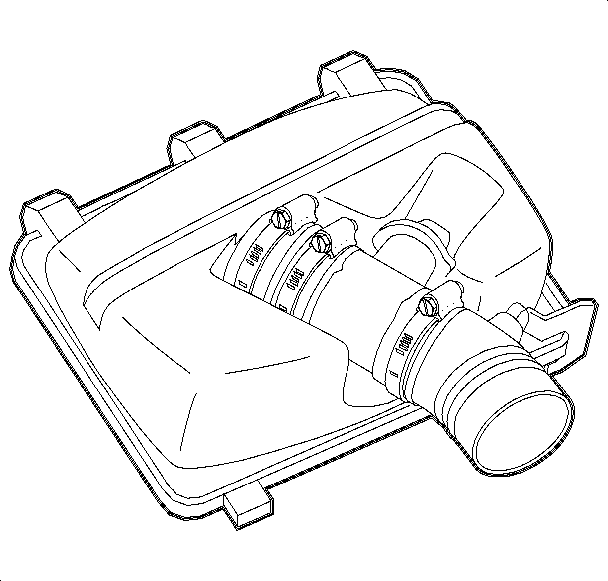
- Remove the intake hose assembly.
- Remove the bank 1 (rear) intake runner.
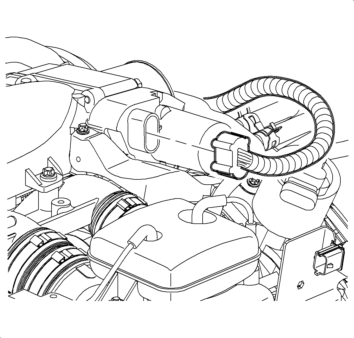
- Disconnect the throttle body electrical connection.
- Disconnect the electrical connection and remove the vacuum hoses from the intake plenum switch-over valve solenoid.
- Remove the vacuum hose from the fuel pressure regulator.
- Remove the front intake plenum-to-runner hose clamp and plenum bolts.
- Remove the EGR manifold bolts.
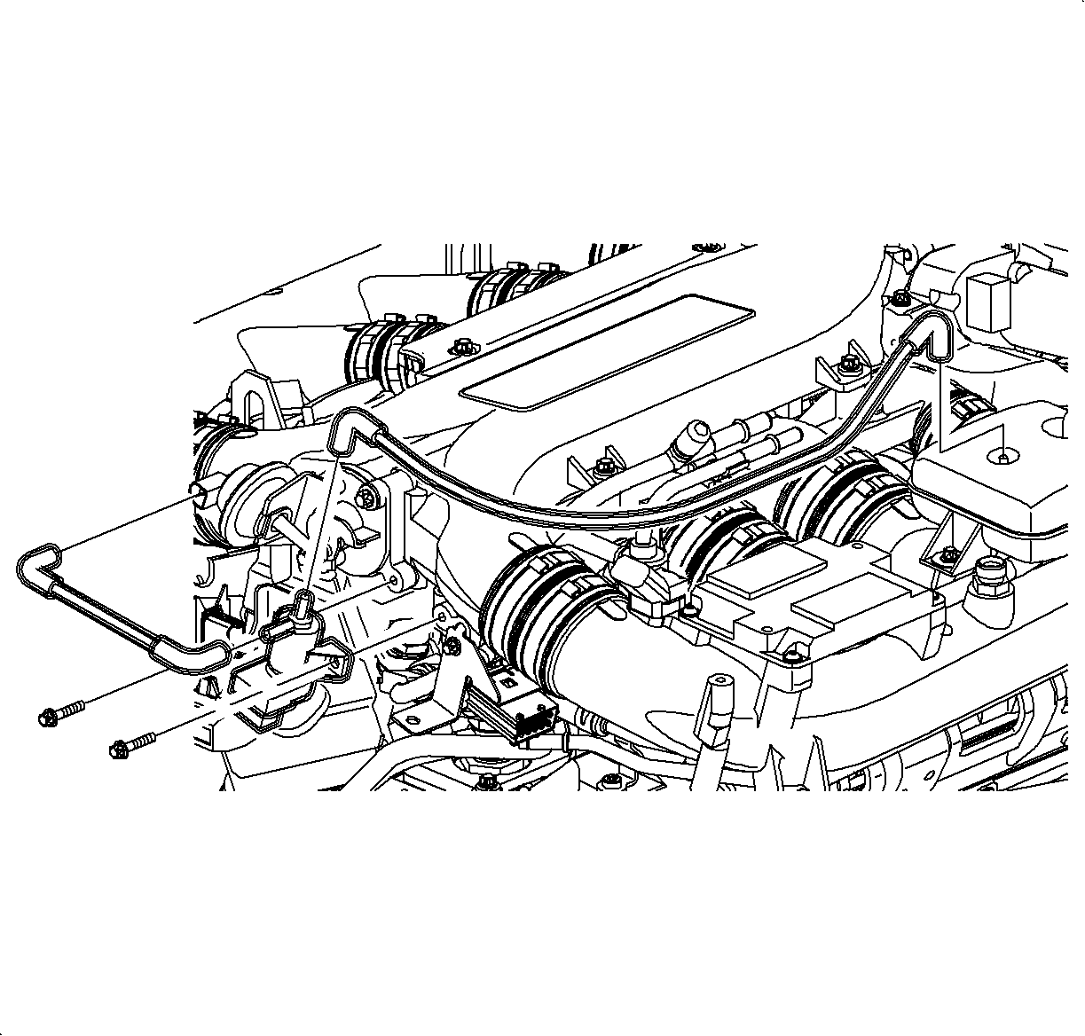
- Lift the plenum and remove the throttle body heater hoses.
- Remove the intake plenum.
- Disconnect the rear coil connection.
- Disconnect the oil separator hose, vacuum line and remove the coolant line bracket from the crankcase vent housing.
- Remove the crankcase vent housing flange bolts and remove the housing.
- Clean the ventilation housing and sealing flange on the engine block.
- Inspect the rubber reed valve for cracks and proper function. Replace the reed valve, if defective.
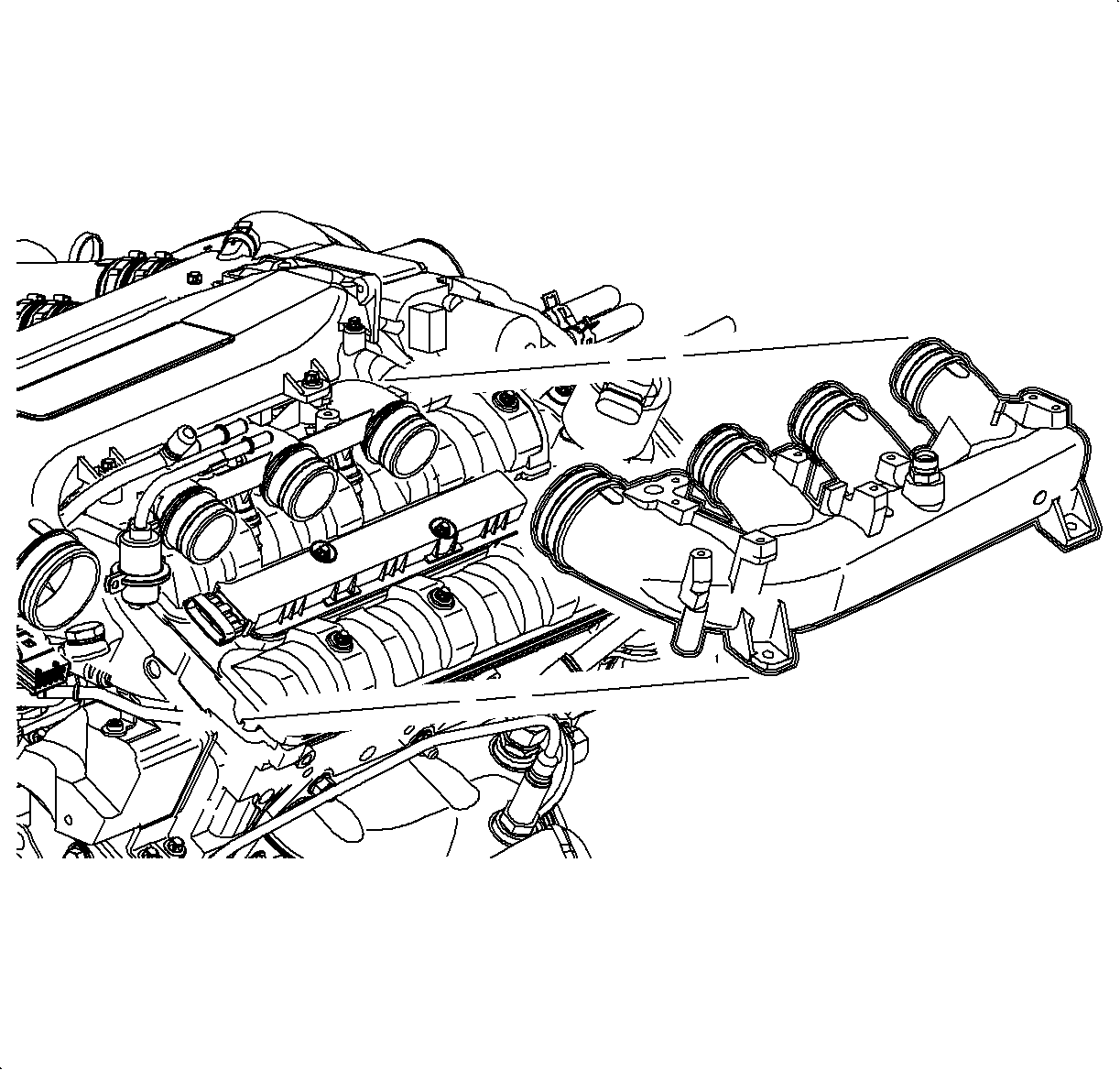
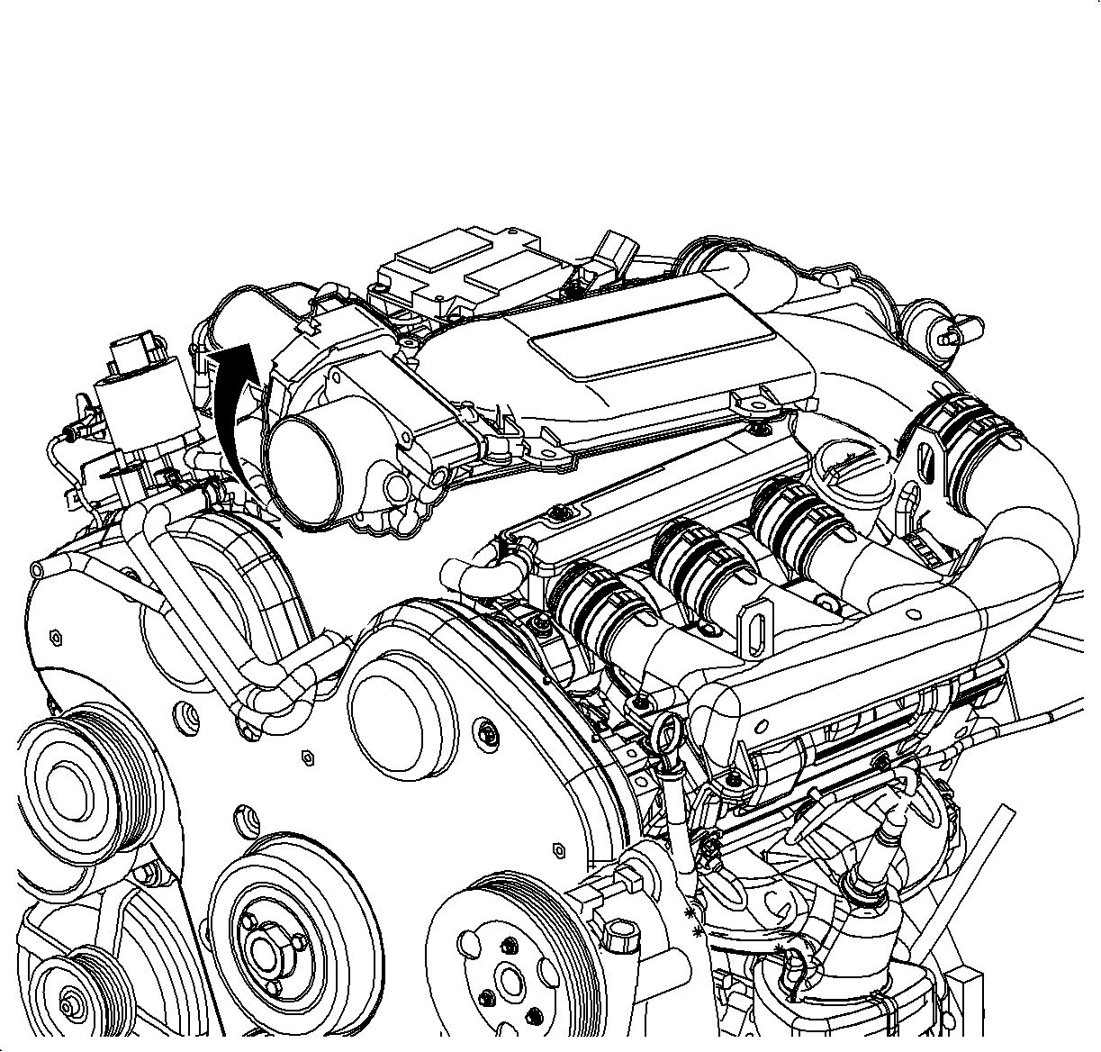
Notice: Mask off the ports to the intake manifold spacer. Failure to mask off the ports may allow foreign objects to enter the engine resulting in severe damage to the engine.
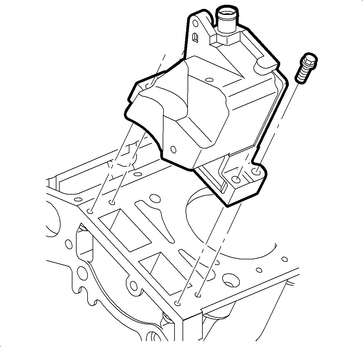
Important: To ensure the positive sealing of flange sealant, thoroughly clean all mating surfaces.
Important: Located within the ventilation housing is a one-way reed valve. The reed valve maintains a positive crankcase pressure.
Installation Procedure
- Apply sealing compound LOCTITE® 518, or equivalent, to the sealing surfaces.
- Install the ventilation housing to the engine block.
- Install the ventilation housing bolts.
- Connect the oil separator hose, vacuum line and install the coolant line bracket to the vent housing.
- Connect the rear coil electrical connection.
- Remove the tape from the intake ports and install the intake plenum into the front intake runner.
- Lift the intake plenum and install the throttle body heater hoses to the underside of the throttle body.
- Lower the intake plenum and install the plenum and EGR manifold bolts.
- Install the fuel pressure regulator vacuum hose.
- Connect the intake plenum switch-over valve solenoid electrical connection and vacuum hoses.
- Connect the throttle body electrical connection.
- Install the bank 1 (rear) intake runner.
- Install the intake hose assembly.
- Connect the negative battery cable.

Notice: Refer to Fastener Notice in the Preface section.
Tighten
Tighten the ventilation housing bolts to 8 N·m
(71 lb in).

Tighten
| • | Tighten the intake plenum bolts to 8 N·m (71 lb in). |
| • | Tighten the EGR manifold bolt to 8 N·m (71 lb in). |


Tighten
Tighten the battery terminal bolts to 17 N·m
(13 lb ft).
