| Table 1: | Accelerator Pedal Position (APP) Sensors |
| Table 2: | Camshaft Position (CMP) Sensor |
| Table 3: | Crankshaft Position (CKP) Sensor |
| Table 4: | Evaporative Emissions (EVAP) Canister Purge Solenoid |
| Table 5: | Evaporative Emissions (EVAP) Canister Vent Solenoid |
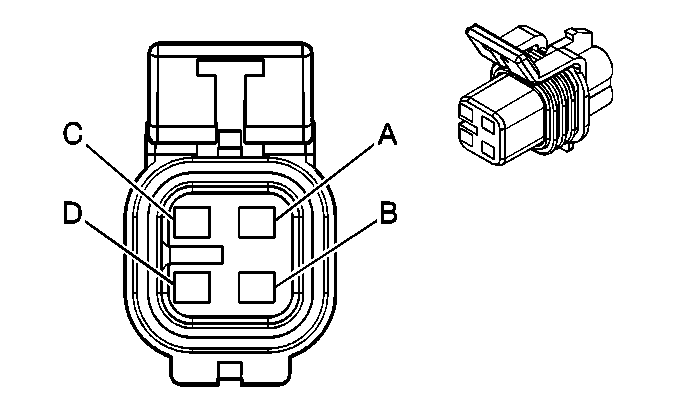
| Table 6: | Fuel Injectors |
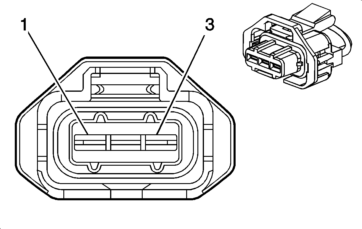
| Table 7: | Fuel Pump and Sender Assembly |
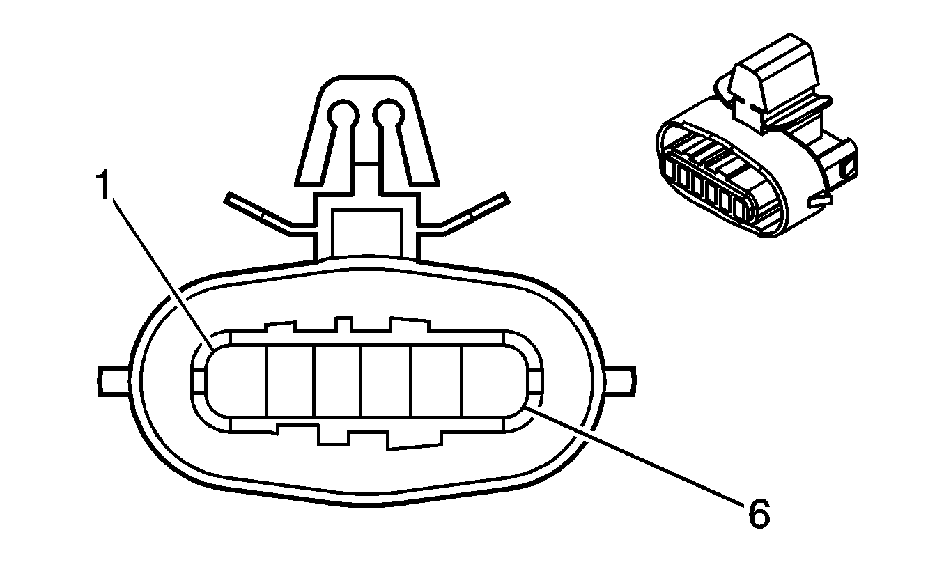
| Table 8: | Fuel Tank Pressure (FTP) Sensor |
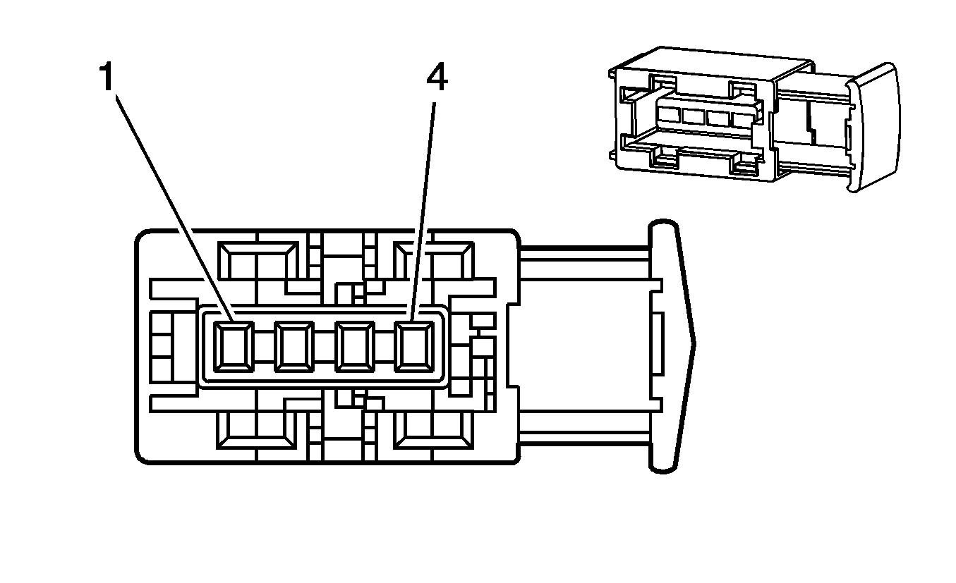
| Table 9: | Heated Oxygen Sensor (HO2S) Bank 1 Sensor 1 |
| Table 10: | Heated Oxygen Sensor (HO2S) Bank 1 Sensor 2 |
| Table 11: | Heated Oxygen Sensor (HO2S) Bank 2 Sensor 1 |
| Table 12: | Heated Oxygen Sensor (HO2S) Bank 2 Sensor 2 |
| Table 13: | Ignition Control Module (ICM) Bank 1 |
| Table 14: | Ignition Control Module (ICM) Bank 2 |
| Table 15: | Intake Manifold Runner Control Solenoid |
| Table 16: | Knock Sensor (KS) 1 |
| Table 17: | Knock Sensor (KS) 2 |
| Table 18: | Mass Air Flow (MAF) Sensor |
| Table 19: | Throttle Actuator Control (TAC) Module |

| |||||||
|---|---|---|---|---|---|---|---|
Connector Part Information |
| ||||||
Pin | Wire Color | Circuit No. | Function | ||||
1 | YE | 1274 | 5-Volt Reference | ||||
2 | BN | 1164 | 5-Volt Reference | ||||
3 | GY | 1161 | APP Sensor 1 Signal | ||||
4 | PK | 1271 | Low Reference | ||||
5 | GN | 2759 | Low Reference | ||||
6 | WH | 1162 | APP Sensor 2 Signal | ||||
| |||||||
|---|---|---|---|---|---|---|---|
Connector Part Information |
| ||||||
Pin | Wire Color | Circuit No. | Function | ||||
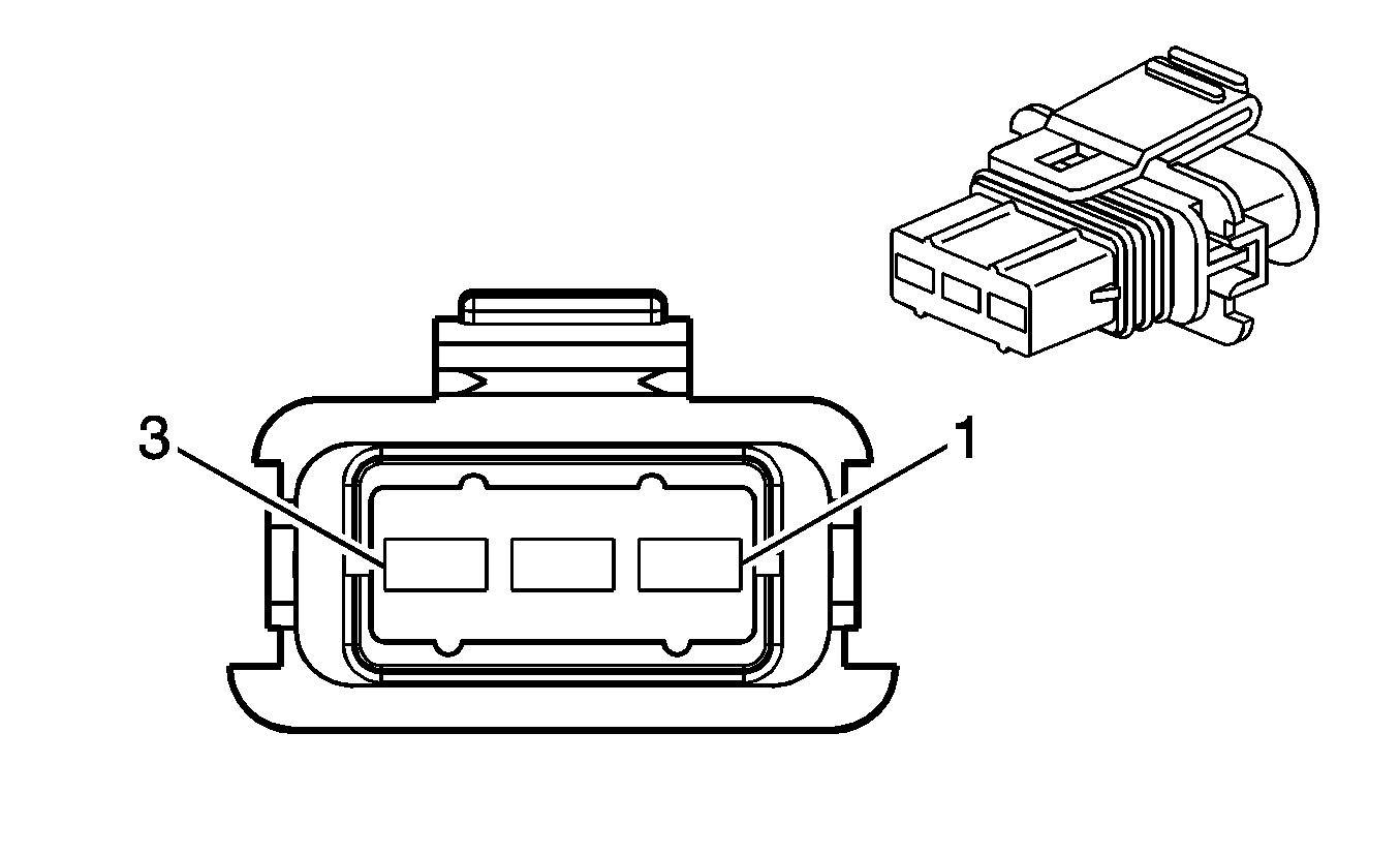
1 | PU/WH | 652 | Low Reference | ||||
2 | BN/WH | 633 | CMP Sensor Signal | ||||
3 | GY | 416 | 5-Volt Reference A | ||||

| |||||||
|---|---|---|---|---|---|---|---|
Connector Part Information |
| ||||||
Pin | Wire Color | Circuit No. | Function | ||||
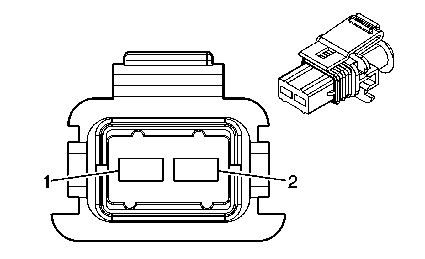
1 | PU | 574 | Low Reference | ||||
2 | YE | 573 | CKP Sensor Signal | ||||
3 | BK/WH | 451 | Ground | ||||
| |||||||
|---|---|---|---|---|---|---|---|
Connector Part Information |
| ||||||
Pin | Wire Color | Circuit No. | Function | ||||
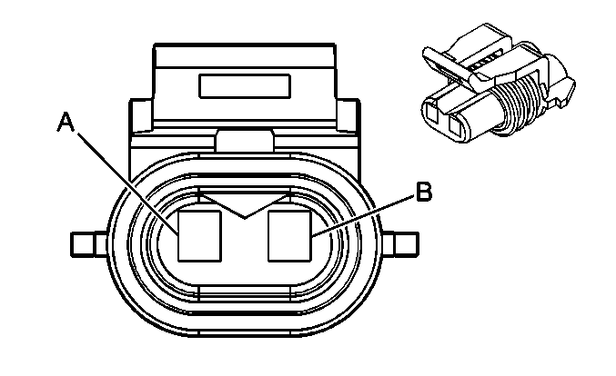
1 | OG | 2440 | Battery Positive Voltage | ||||
2 | D-GN/WH | 428 | EVAP Canister Purge Solenoid Control | ||||
| |||||||
|---|---|---|---|---|---|---|---|
Connector Part Information |
| ||||||
Pin | Wire Color | Circuit No. | Function | ||||
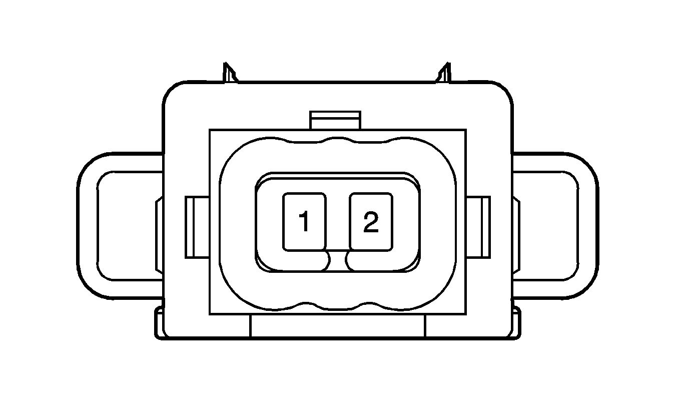
A | OG | 2740 | Ignition 1 Voltage | ||||
B | WH | 1310 | EVAP Canister Vent Solenoid Control | ||||
| |||||||
|---|---|---|---|---|---|---|---|
Connector Part Information |
| ||||||
Pin | Wire Color | Circuit No. | Function | ||||
1 | RD/BU | 2640 | Ignition 1 Voltage | ||||
2 | BN/YE | 1744 | Fuel Injector 1 Control (Injector 1) | ||||
BN/L-GN | 1745 | Fuel Injector 2 Control (Injector 2) | |||||
BN/BU | 1746 | Fuel Injector 3 Control (Injector 3) | |||||
BN/RD | 844 | Fuel Injector 4 Control (Injector 4) | |||||
BN/BK | 845 | Fuel Injector 5 Control (Injector 5) | |||||
BN/PU | 846 | Fuel Injector 6 Control (Injector 6) | |||||
| |||||||
|---|---|---|---|---|---|---|---|
Connector Part Information |
| ||||||
Pin | Wire Color | Circuit No. | Function | ||||
A | PU | 30 | Fuel Level Sensor Signal | ||||
B | GY | 120 | Fuel Pump Supply Voltage | ||||
C | BK | 650 | Ground | ||||
D | BK | 2759 | Low Reference | ||||
| |||||||
|---|---|---|---|---|---|---|---|
Connector Part Information |
| ||||||
Pin | Wire Color | Circuit No. | Function | ||||
1 | GY | 2709 | 5-Volt Reference A | ||||
2 | BK | 2759 | Low Reference | ||||
3 | D-GN | 890 | Fuel Tank Pressure Sensor Signal | ||||
| |||||||
|---|---|---|---|---|---|---|---|
Connector Part Information |
| ||||||
Pin | Wire Color | Circuit No. | Function | ||||
1 | PU/WH | 1665 | HO2S Input Pump Current | ||||
2 | PU | 412 | HO2S Reference Voltage | ||||
3 | TN | 413 | HO2S Low Reference | ||||
4 | BK/WH | 751 | HO2S Heater Low Control | ||||
5 | OG | 2740 | Ignition 1 Voltage | ||||
6 | TN | 1667 | HO2S Output Pump Current | ||||
| |||||||
|---|---|---|---|---|---|---|---|
Connector Part Information |
| ||||||
Pin | Wire Color | Circuit No. | Function | ||||
1 | OG | 2440 | Ignition 1 Voltage | ||||
2 | BK/WH | 151 | HO2S Heater Low Control | ||||
3 | TN/WH | 1669 | HO2S Low Signal | ||||
4 | PU/WH | 1668 | HO2S High Signal | ||||

| |||||||
|---|---|---|---|---|---|---|---|
Connector Part Information |
| ||||||
Pin | Wire Color | Circuit No. | Function | ||||
1 | PU | 1666 | HO2S Input Pump Current | ||||
2 | TN/WH | 1653 | HO2S Reference Voltage | ||||
3 | GY | 1979 | HO2S Low Reference | ||||
4 | TN/WH | 551 | HO2S Heater Low Control | ||||
5 | OG | 2440 | Ignition 1 Voltage | ||||
6 | TN | 1664 | HO2S Output Pump Current | ||||

| |||||||
|---|---|---|---|---|---|---|---|
Connector Part Information |
| ||||||
Pin | Wire Color | Circuit No. | Function | ||||
1 | OG | 2740 | Ignition 1 Voltage | ||||
2 | BK/WH | 51 | HO2S Heater Low Control | ||||
3 | GY | 1981 | HO2S High Signal | ||||
4 | TN | 1671 | HO2S Low Signal | ||||
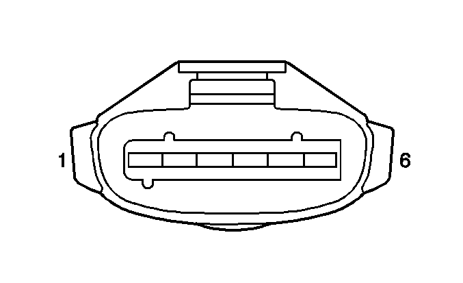
| |||||||
|---|---|---|---|---|---|---|---|
Connector Part Information |
| ||||||
Pin | Wire Color | Circuit No. | Function | ||||
1 | BK | 250 | Ground | ||||
2 | PK | 1539 | Ignition 1 Voltage | ||||
3 | YE | 1157 | Ignition Coil 5 Control | ||||
4 | PK | 1155 | Ignition Coil 3 Control | ||||
5 | L-BU | 1153 | Ignition Coil 1 Control | ||||
6 | -- | -- | Not Used | ||||
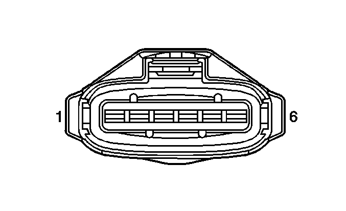
| |||||||
|---|---|---|---|---|---|---|---|
Connector Part Information |
| ||||||
Pin | Wire Color | Circuit No. | Function | ||||
1 | BK | 250 | Ground | ||||
2 | PK | 1539 | Ignition 1 Voltage | ||||
3 | TN | 1158 | Ignition Coil 6 Control | ||||
4 | PU | 1156 | Ignition Coil 4 Control | ||||
5 | D-BU | 1154 | Ignition Coil 2 Control | ||||
6 | -- | -- | Not Used | ||||

| |||||||
|---|---|---|---|---|---|---|---|
Connector Part Information |
| ||||||
Pin | Wire Color | Circuit No. | Function | ||||
1 | L-BU | 1110 | IMRC Solenoid Control | ||||
2 | OG | 2640 | Ignition 1 Voltage | ||||

| |||||||
|---|---|---|---|---|---|---|---|
Connector Part Information |
| ||||||
Pin | Wire Color | Circuit No. | Function | ||||
1 | D-BU | 496 | Knock Sensor 1 Signal | ||||
2 | YE/BK | 457 | Low Reference | ||||

| |||||||
|---|---|---|---|---|---|---|---|
Connector Part Information |
| ||||||
Pin | Wire Color | Circuit No. | Function | ||||
1 | L-BU | 1876 | Knock Sensor 2 Signal | ||||
2 | YE/BK | 452 | Low Reference | ||||
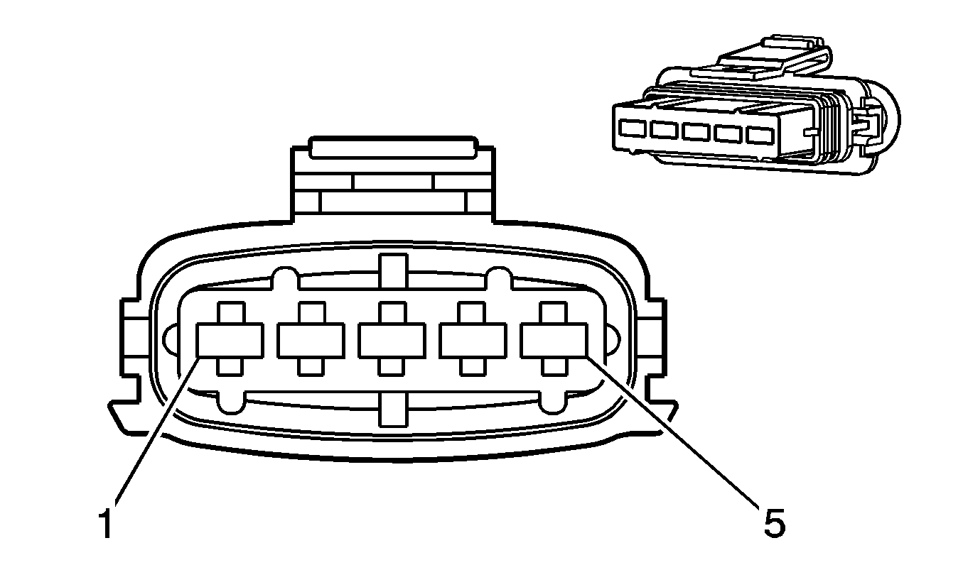
| |||||||
|---|---|---|---|---|---|---|---|
Connector Part Information |
| ||||||
Pin | Wire Color | Circuit No. | Function | ||||
1 | TN | 472 | IAT Sensor Signal | ||||
2 | OG | 2440 | Ignition 1 Voltage | ||||
3 | PU/WH | 652 | Low Reference | ||||
4 | GY | 416 | 5-Volt Reference A | ||||
5 | YE | 492 | MAF Sensor Signal | ||||
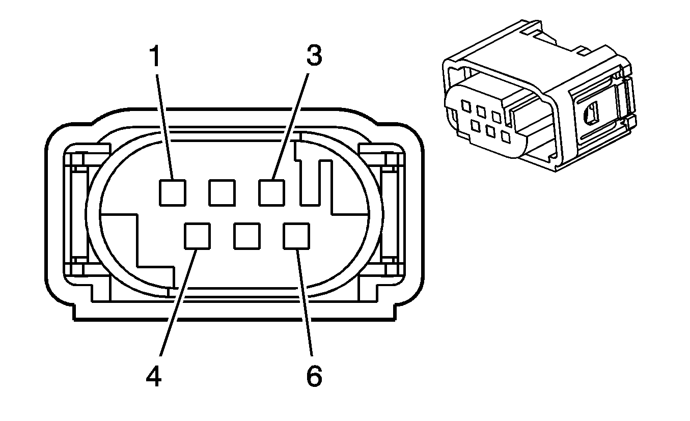
| |||||||
|---|---|---|---|---|---|---|---|
Connector Part Information |
| ||||||
Pin | Wire Color | Circuit No. | Function | ||||
1 | YE | 581 | TAC Motor Control 1 | ||||
2 | PU/WH | 652 | Low Reference | ||||
3 | PU | -- | 5-Volt Reference | ||||
4 | BN | 582 | TAC Motor Control 2 | ||||
5 | D-GN | -- | TP Sensor 2 Signal | ||||
6 | YE/BK | -- | TP Sensor 1 Signal | ||||
