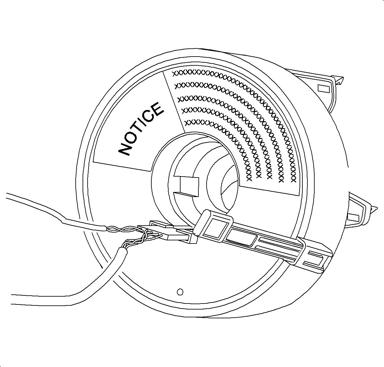
Repositioning Procedure
- Gently rotate the coil hub clockwise with the tab removed until a slight tension is present.
- Gently rotate the coil hub counterclockwise (count approximately 5 revolutions) until a slight tension is present
- Gently rotate the coil hub clockwise one half of the number of revolutions counted in step 2 (approximately 2.5 times).
- Rotate the smallest distance required to align the yellow tab.
- Install the yellow tab. Use tape is the tab is unavailable.
Caution: Refer to SRS Sodium Hydroxide Powder Caution in the Preface section.
Caution: Refer to SIR Inflator Module Handling and Storage Caution in the Preface section.

Important: In the event deployment has occurred, refer to Repairs and Inspections Required After a Collision .
Notice: If roll connector is not properly oriented to steering column assembly, it will be damaged.
Important: If the yellow tab is inadvertently removed during installation or removal and the roll connector hub has been rotated, it must be repositioned.
Removal Procedure
- Position the vehicle with the front wheels pointed straight ahead and the steering wheel centered.
- Disable the SIR system. Refer to SIR Disabling and Enabling .
- Remove the driver inflator module. Refer to the Inflatable Restraint Steering Wheel Module Replacement .
- Remove the steering wheel attachment nut and discard. Refer to Steering Wheel Replacement in Steering Wheel and Column.
- Insert the yellow tab or use a piece of tape to prevent the roll connector from rotating.
- Remove the upper steering column cover, and lower the steering column cover attachment. Refer to Steering Column Trim Covers Replacement in Steering Wheel and Column.
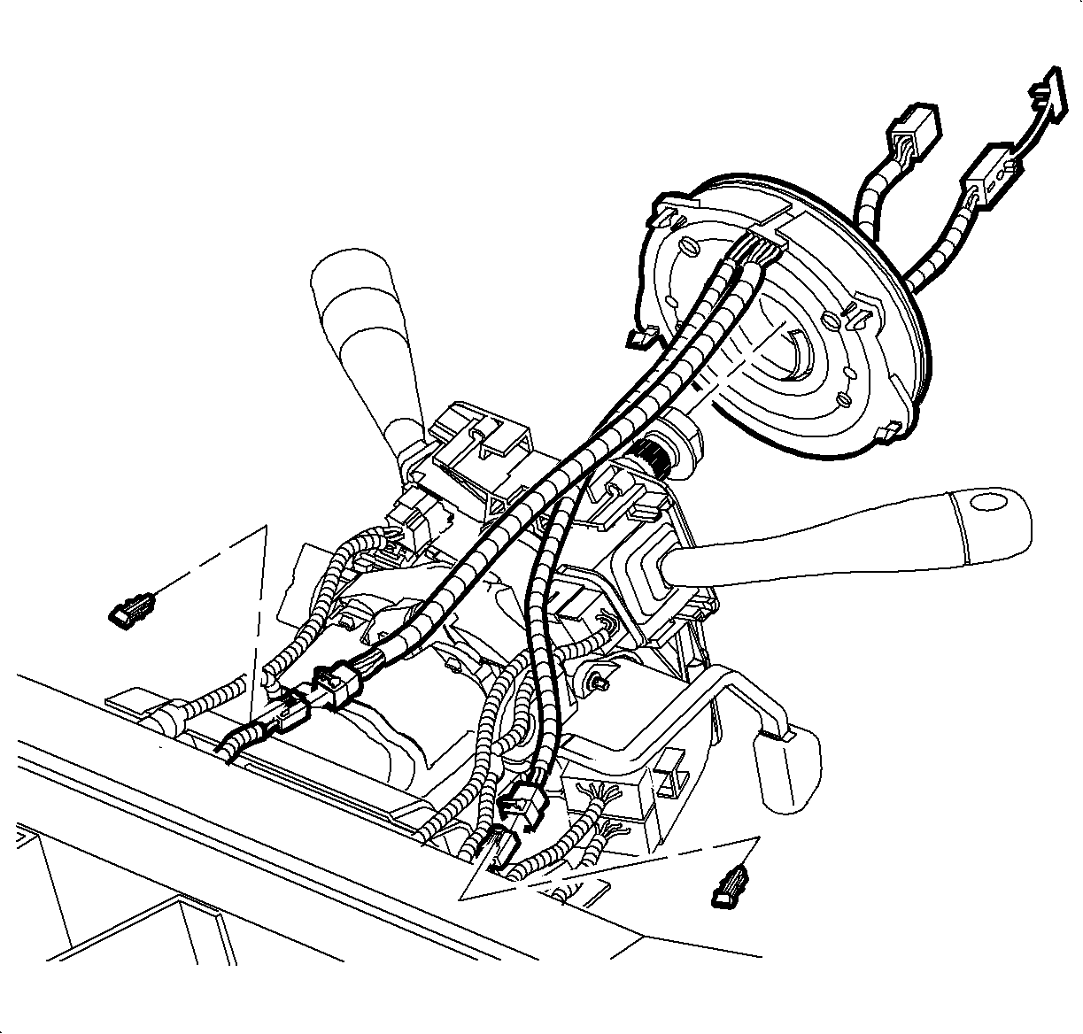
- Remove the roll connector rosebud-type fastener from the bracket below the steering column.
- Disconnect the horn/cruise connector under the steering column.
- Remove the roll connector by carefully prying the plastic retainers.
- Guide the roll connector wiring harness from behind the lever control switch and remove the roll connector.
Caution: Refer to Title not found in the Preface section.
Important: Always align the front wheels to the straight ahead position when removing or installing a roll connector.
Important: If a roll connector is removed without the wheels in the straight ahead position, the same roll connector may be installed if the steering shaft and the coil hub have not rotated.
Important: If a roll connector is removed without the wheels in the straight ahead position, the same roll connector may be installed if the steering shaft and coil have not rotated.

Installation Procedure
- Route the SIR wiring harness and horn/cruise connector behind the turn signal lever combination switch and down the steering column.
- Install the roll connector to the turn signal lever combination switch housing.
- Install the upper and lower steering column trim covers. Refer to Steering Column Trim Covers Replacement .
- Install the steering wheel. Refer to Steering Wheel Replacement in Steering Wheel and Column.
- Install the driver inflator module. Be sure to seat all the attachment points. Refer to Inflatable Restraint Steering Wheel Module Replacement in Steering Wheel and Column.
- Enable the SIR system. Refer to SIR Disabling and Enabling .

Important: A new roll connector is equipped with a yellow tab that is removed after the steering wheel is installed. This tab passes through the steering wheel.
Notice: Refer to Fastener Notice in the Preface section.
