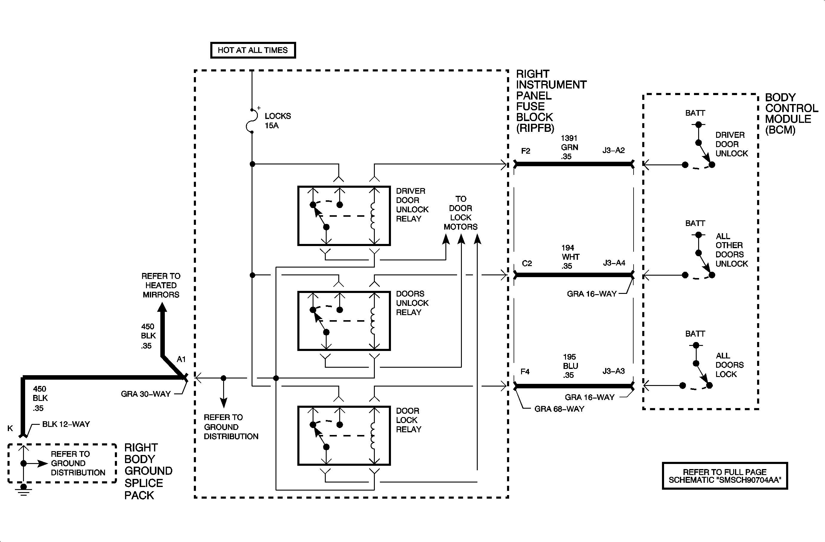
Circuit Description
The body control module (BCM) controls the door lock relay. Voltage is applied to the door lock relay through the door lock relay control circuit when the BCM senses a door lock switch activation or a keyless entry lock command.
DTC Descriptors
This diagnostic procedure supports the following DTCs:
| • | DTC B3137 All Door Lock Circuit Low |
| • | DTC B3138 All Door Lock Circuit High |
Conditions for Running the DTC
Battery positive voltage is between 9-16 volts.
Conditions for Setting the DTC
| • | The BCM detects an open in the door lock relay control. This condition must be present for more than 0.3 seconds. |
| • | The BCM detects a short to ground in the door lock relay control while commanding the door lock relay. This condition must be present for more than 0.3 seconds. |
Action Taken When the DTC Sets
| • | The door lock relay will be inoperative. |
| • | The BCM stores either DTC B3137 or DTC B3138 in memory. |
Conditions for Clearing the DTC
| • | A history DTC will clear after 100 consecutive fault-free ignition cycles. |
| • | A scan tool may be used to clear the DTC. |
Diagnostic Aids
| • | The following conditions may cause the DTC to set: |
| - | An open or short to ground in the door lock relay control circuit |
| - | A faulty door lock relay |
| - | The BCM is shorted to ground internally. |
| • | If the DTCs are a history DTC, the fault may be intermittent. Refer to Testing for Intermittent Conditions and Poor Connections in Wiring Systems. |
Test Description
The numbers below refer to the step numbers on the diagnostic table.
-
Listen for an audible noise when the door lock relay is commanded. Command the door locks to lock and unlock. Repeat the commands as necessary.
-
This step verifies that the BCM is providing voltage to the door lock relay.
-
This step tests for an open in the door lock relay ground circuit.
Step | Action | Yes | No |
|---|---|---|---|
Schematic Reference: Door Lock/Indicator Schematics Connector End View Reference: Power Door Systems Connector End Views | |||
1 | Did you perform the Diagnostic System Check - Vehicle? | Go to Step 2 | Go to Diagnostic System Check - Vehicle in Vehicle DTC Information |
Does the door lock relay energize when commanded? | Go to Diagnostic Aids | Go to Step 3 | |
Does the test lamp flash when the door lock relay is commanded ON? | Go to Step 4 | Go to Step 5 | |
Connect a test lamp between the door lock relay ground circuit and battery positive voltage. Does the test lamp illuminate? | Go to Step 7 | Go to Step 8 | |
5 | Test for an open or short to ground in the door lock relay control circuit. Refer to Circuit Testing and Wiring Repairs in Wiring Systems. Did you find and correct the condition? | Go to Step 12 | Go to Step 6 |
6 | Inspect for poor connections at the body control module (BCM). Refer to Testing for Intermittent Conditions and Poor Connections and Connector Repairs in Wiring Systems. Did you find and correct the condition? | Go to Step 12 | Go to Step 9 |
7 | Inspect for poor connections at the door lock relay. Refer to Testing for Intermittent Conditions and Poor Connections and Connector Repairs in Wiring Systems. Did you find and correct the condition? | Go to Step 12 | Go to Step 10 |
8 | Repair the open in the door lock relay ground circuit. Refer to Wiring Repairs in Wiring Systems. Did you complete the repair? | Go to Step 12 | -- |
9 |
Did you complete the replacement? | Go to Step 12 | -- |
10 | Replace the door lock relay. Did you complete the replacement? | Go to Step 12 | -- |
12 |
Does the DTC reset? | Go to Step 2 | System OK |
