Service Information and Installation of Procedures for Trap Resistant Trunk Kit

| Subject: | Service Information and Installation Procedures for Trap-Resistant Trunk Kit. Due to the addition of the 2001 model year and changes in the electrical information of the service procedure, this bulletin has been revised this bulletin supersedes bulletin 99 - T - 52, which should be discarded. |
| Models: | 2000 -- 2001 Saturn L-Series Sedans |
Purpose
The purpose of this bulletin is to inform Saturn retailer personnel of the system function and procedure used to install the Trap-Reisistant Trunk Kit. The Trap-Resistant Trunk Kit is composed of two system components.
The first component of the kit is the trap-resistant latch system. The trap-resistant latch is a modified decklid latch designed to help prevent a child from unintentionally closing and latching the decklid. Once the decklid has been opened by the key, vehicle interior release lever, or remote keyless entry (RKE) transmitter, the trap-resistant latch cannot be re-latched without the user performing a reset function. This reset function consists of cycling the latch reset lever twice after the decklid has been opened in order to enable the latch. If the latch is not enabled the decklid will not latch and will not close.
The second component of the kit is the illuminated interior release handle. The interior release handle is a plastic yellow handle, pocketed in a black plastic housing, which is mounted inside the trunk to the decklid. the interior release handle was designed so that a small child trapped in the trunk could use it to open the decklid. The handle operates the decklid latch mechanically and is illuminated with tow light-emitting diodes (LEDs) when the decklid is closed. The handle remains illuminated for a period of approximately one hour after the decklid is closed. the LEDs create a small parasitic load that will not drain the vehicle battery with normal usage.
After completing the Trap-resistant Trunk Kit installation procedure , use the steps at the end of the procedure to verify proper system operation. Also, be sure to provide the customer with the supplemental owner's handbook insert included in the kit and demonstrate the system operation.
Procedure
Trap-Resistant Latch and Interior Release Handle Installation
- Open decklid.
- Disconnect negative battery cable.
- Remove decklid latch retaining bolts.
- Disconnect lock cylinder release cable from decklid latch.
- Disconnect electrical connectors.
- Remove existing decklid latch and discard.
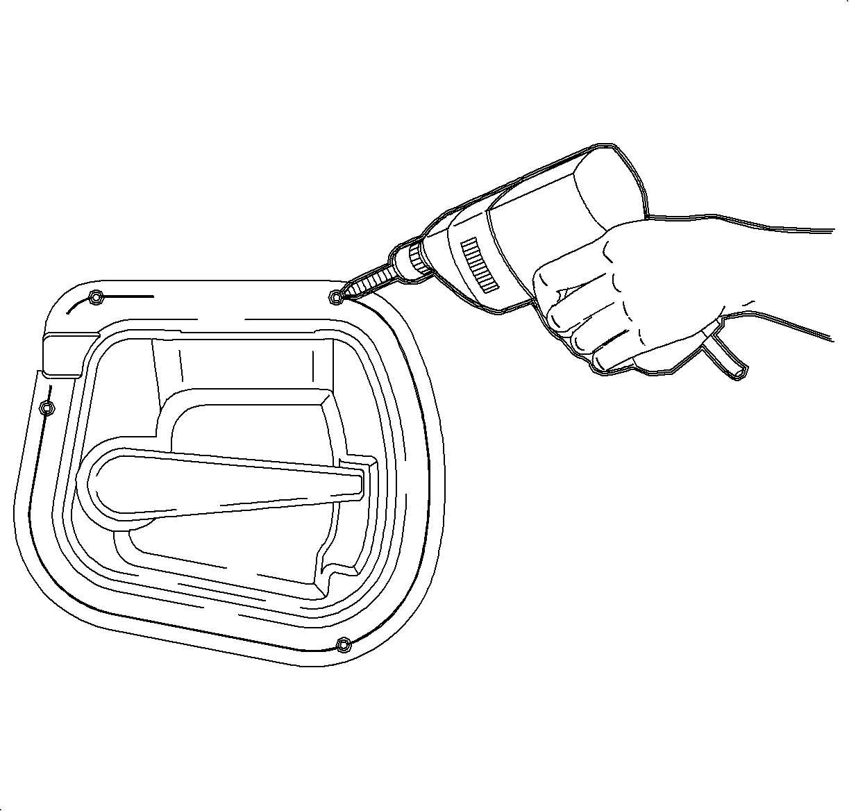
- Cut out center of interior release handle template and place over interior release handle.
- Mark hole location(s) on release handle as shown on template.
- Drill 3mm (1/8) holes at marks on handle.
- Reconnect vehicle lock cylinder release cable end fitting into lower slot of new trap-resistant latch, and clip cable conduit to latch housing.
- Insert release handle cable end fitting into upper slot of new trap-resistant latch, and clip cable conduit to latch housing.
- Route release handle cable through same hole in decklid as lock cylinder release cable.
- Install trap-resistant latch to decklid with original bolts.
- Connect cable end fitting to release handle lever on backside of release handle.
- Connect cable conduit to release handle housing.
- If not already connected, connect release handle wiring harness (included in kit) to release handle.
- Align handle to decklid sheet metal as shown.
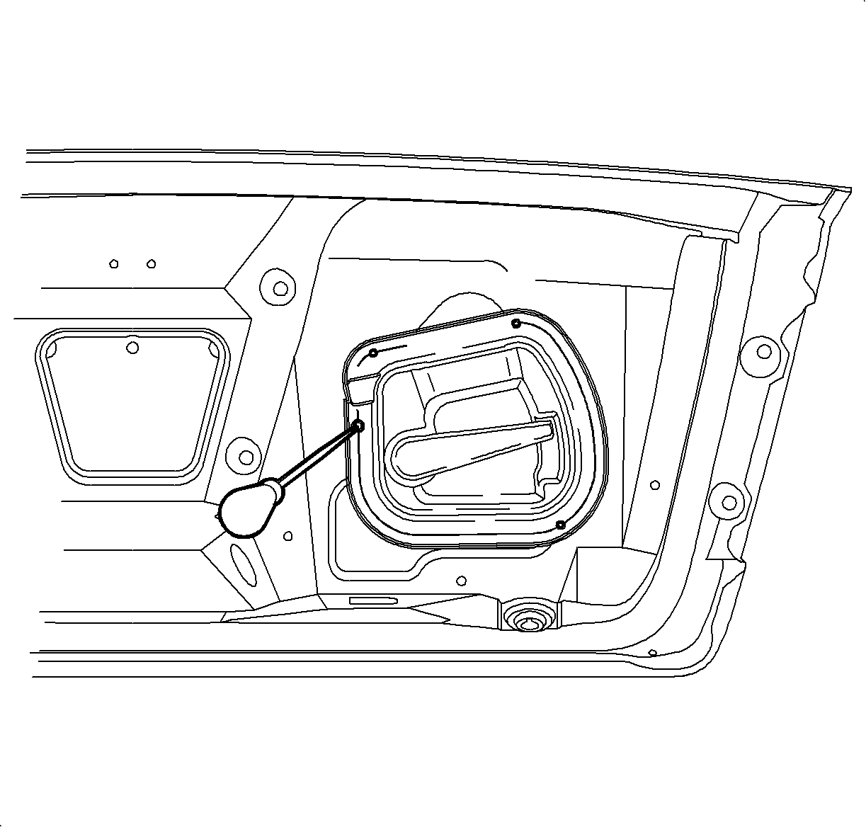
- Using the release handle as a template, mark one hole location on decklid sheet metal.
- Center-punch and drill one 3mm (1/8 in.) hole at mark on decklid.
- Install release handle with one release handle-to-decklid fastener (P/N 11515005 included in kit).
- Using interior release handle as a template, align release handle to decklid.
- Drill 3mm (1/8) holes at remaining attachment locations and install remaining release handle-to-decklid fasteners (P/N 11515005 included in kit).
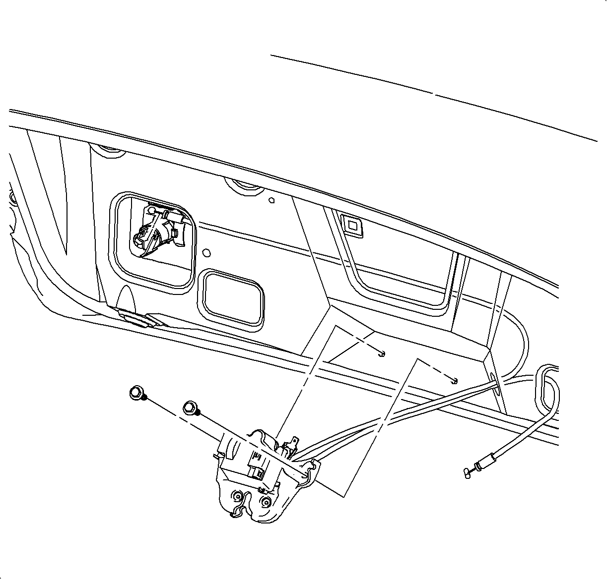
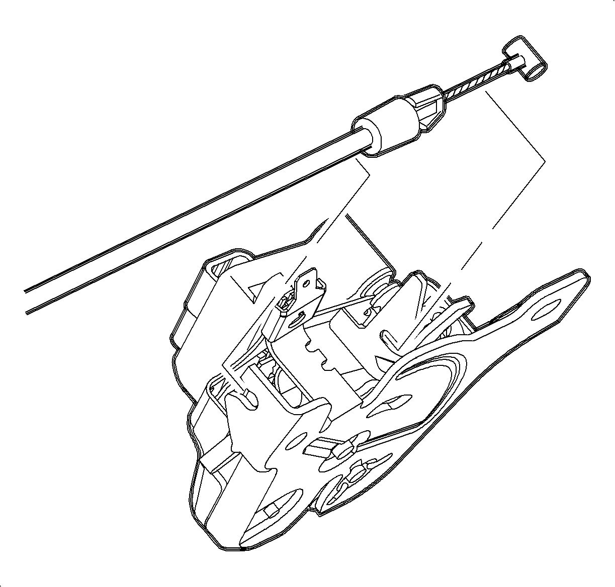
Important: Vehicles equipped with or with the remote keyless entry. (RKE) feature use the same trap-resistant latch that is included in the kit. This latch will function properly on all vehicles.
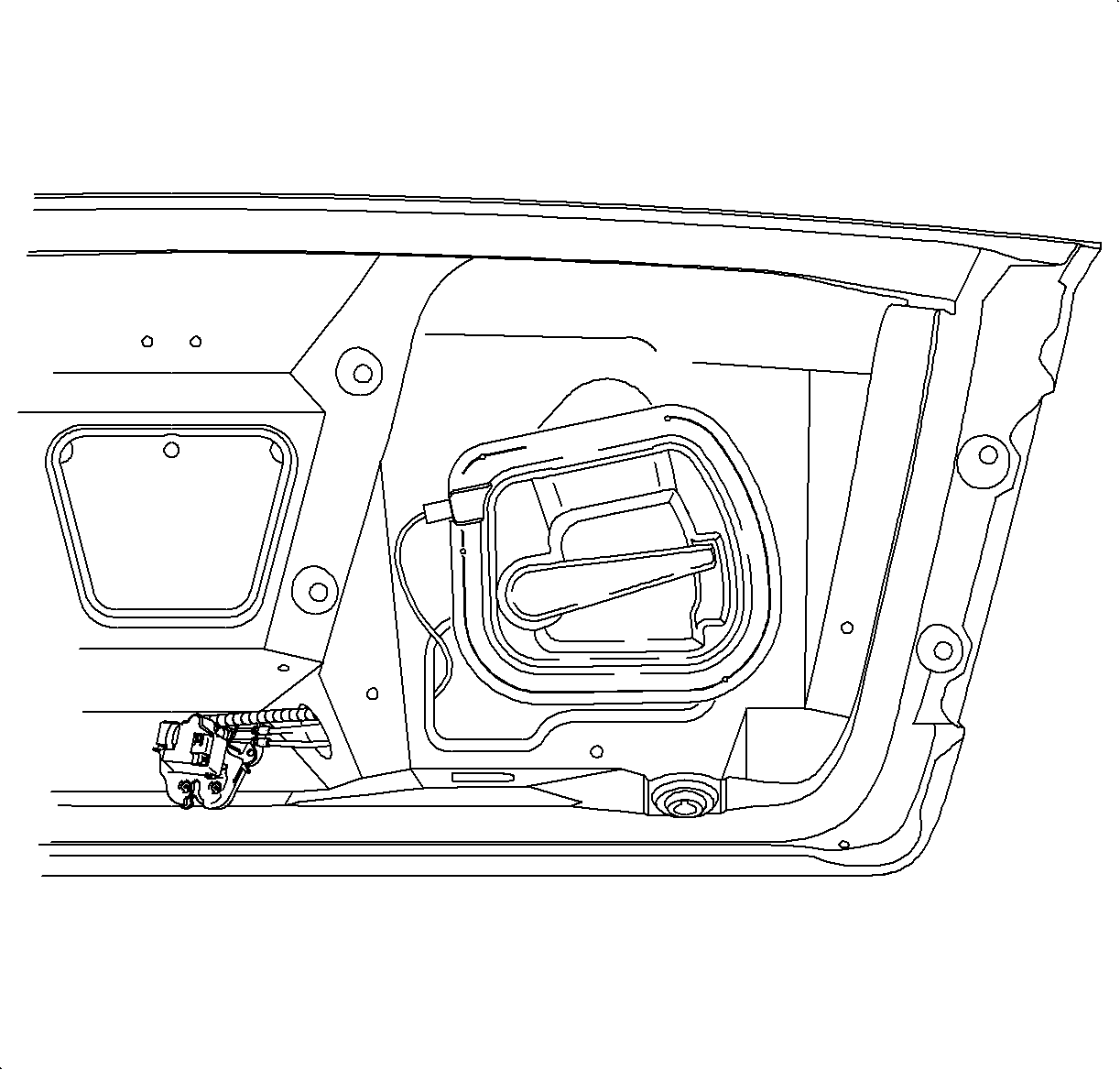

Tighten
Tighten the bolts to 10 N·m (89 lb in).

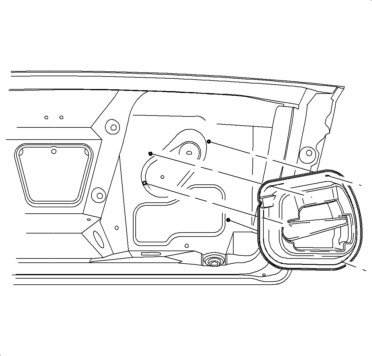
Important: Due to stiffness of cable conduit, it may be necessary to pre-bend cable conduit prior to handle installation.
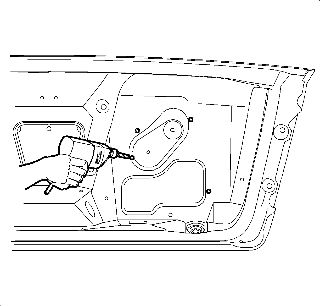
Notice: If drill bit is allowed to drill into sheet metal at a depth greater that 6.5 mm (1/4 in), outer surface of exterior panel may be penetrated.
Tighten
Tighten the fasteners to 2.6 N·m (23 lb in).


Tighten
Tighten the fasteners to 2.6 N·m (23 lb in).
Trap-Resistant Latch and Interior Release Handle Electrical Installation
- Remove left carpet retainer (sill plate) by gently pulling at attaching clip locations from front to rear along retainer.
- Remove storage compartment from console.
- Remove ashtray and auxiliary power outlet from rear side of center console.
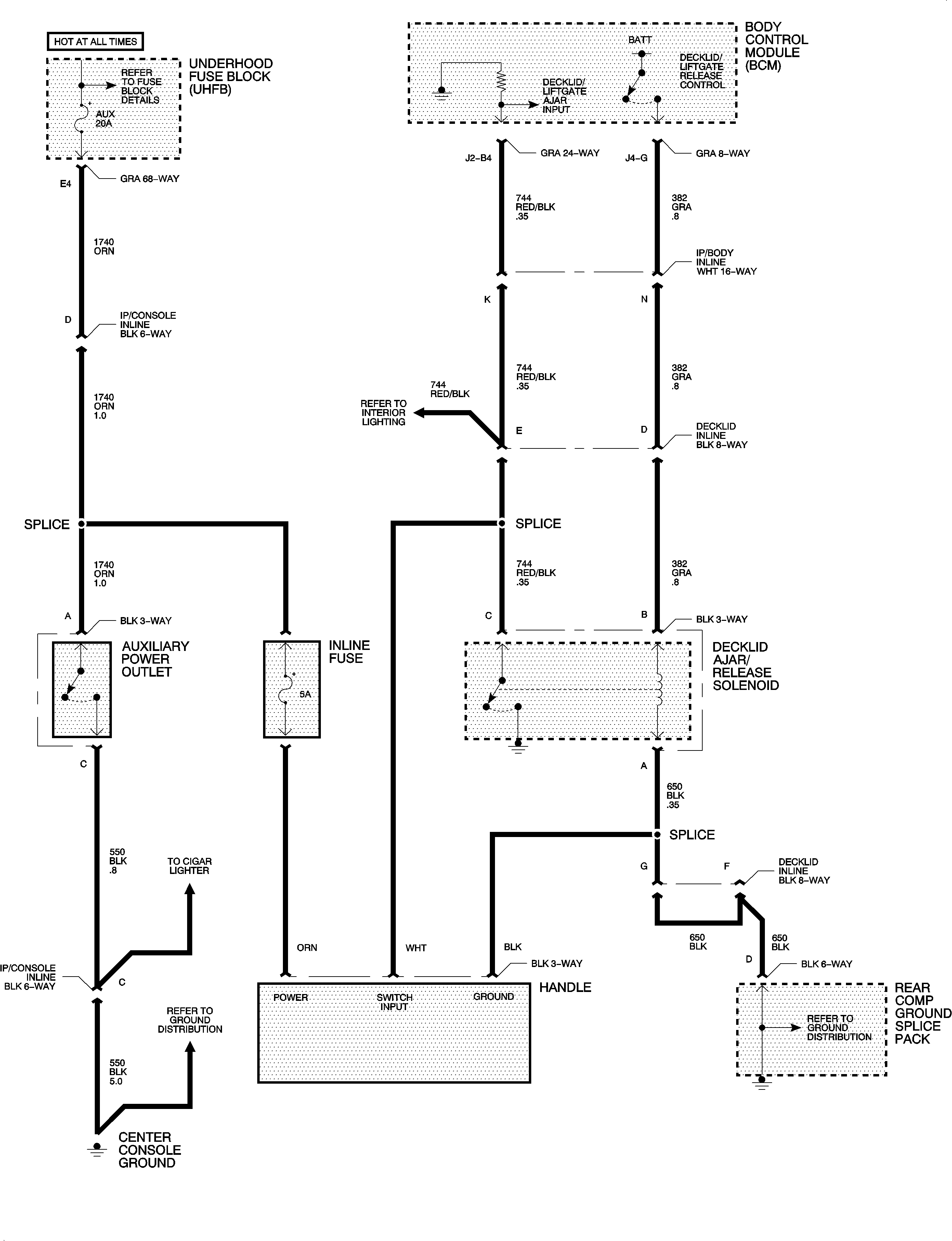
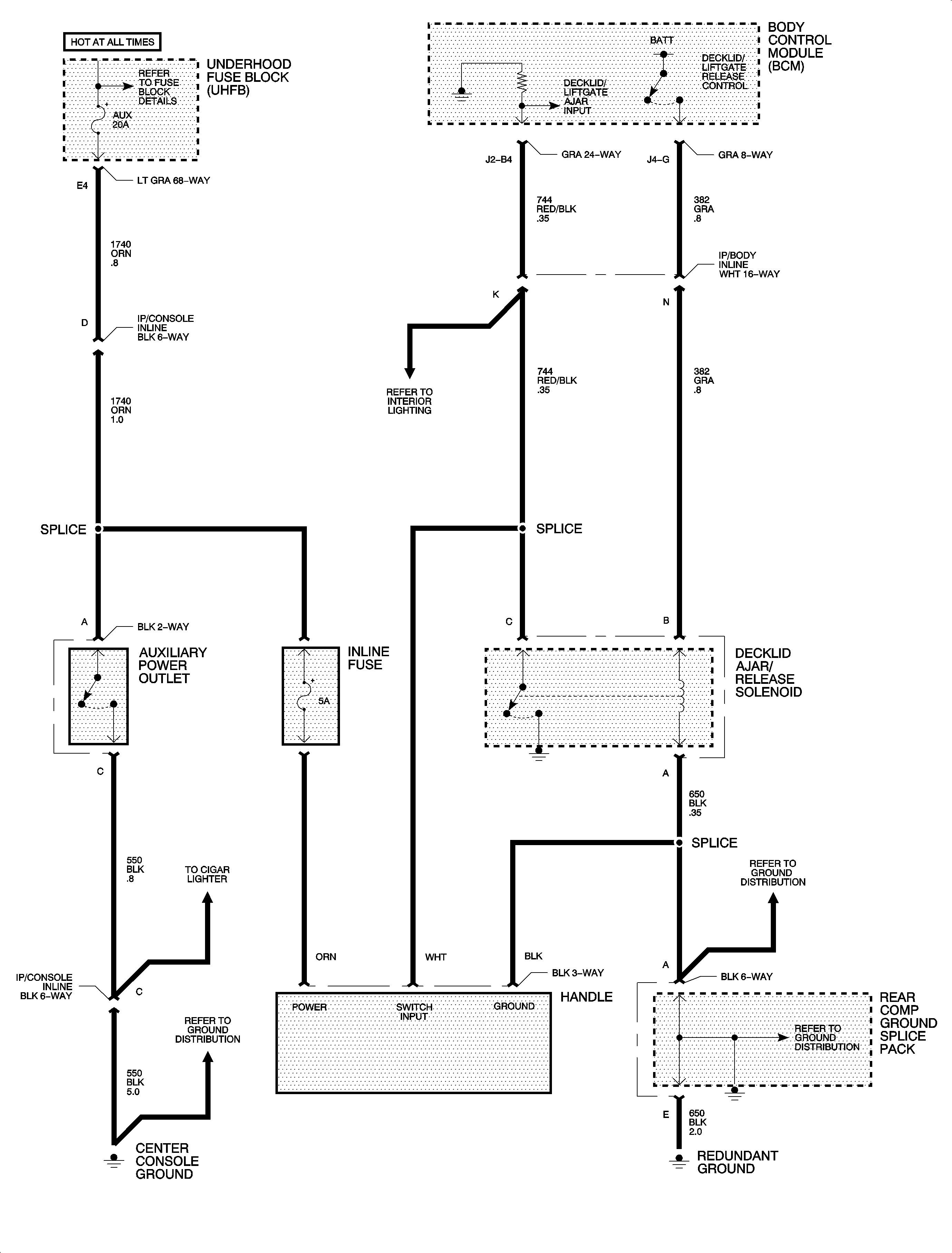
- Locate the ORN power feed wire (ckt 1740 for the auxiliary power outlet.
- Remove left rear seat bolster.
- Remove rear compartment left side carpet. Right side shown, left side similar.
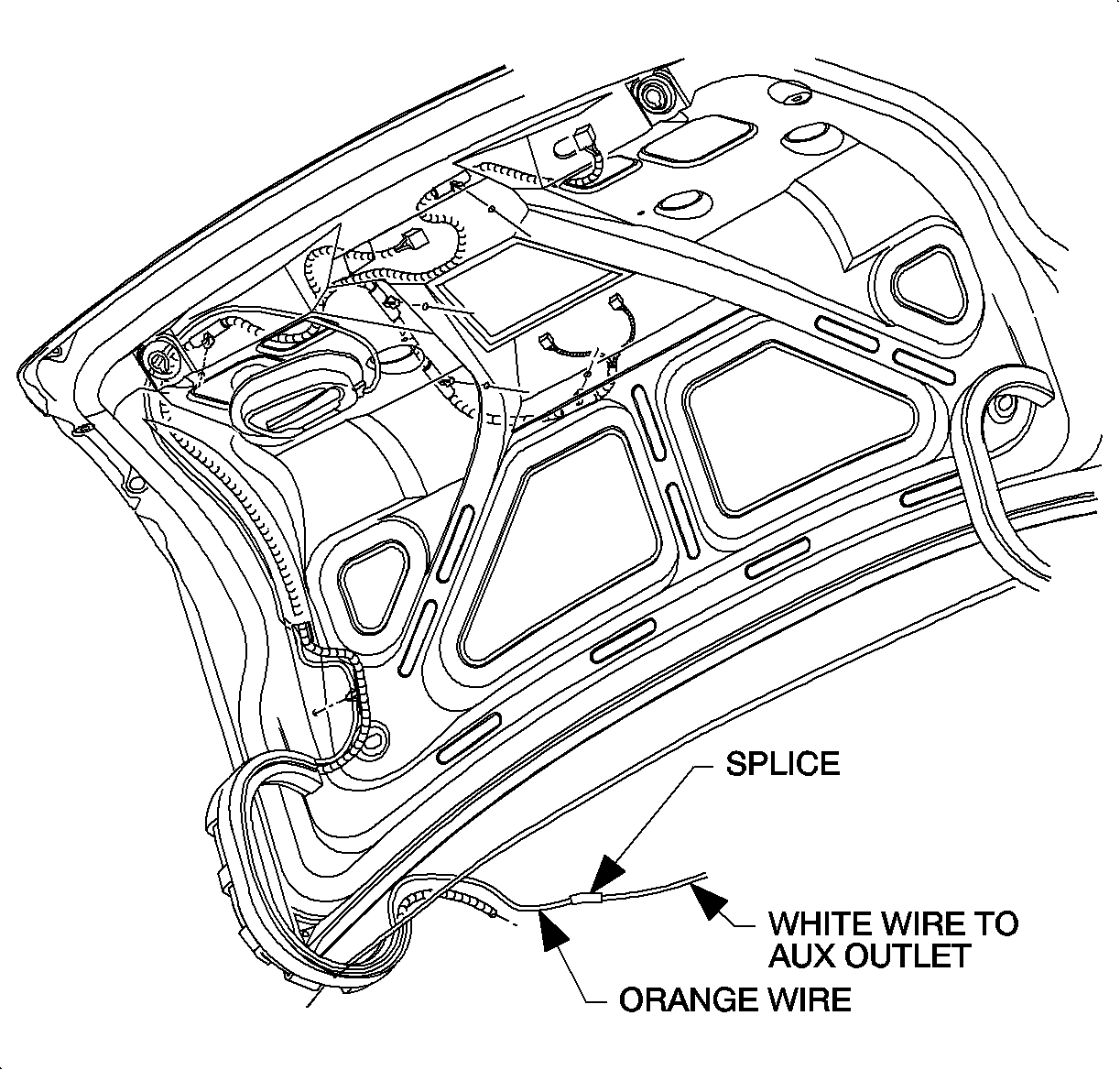
- Route handle ORN wire through decklid along existing vehicle harness and out of hole in decklid.
- Splice blunt cut end of WHT extension wire supplied in kit to handle ORN wire using a crimp and seal splice sleeve. (This acts as an extension wire of the handle ORN wire so it can route up to the console area.)
- Remove decklid wiring harness retainer from left decklid hinge.
- Insert handle ORN wire (with WHT extension wire attached) into decklid wiring harness retainer and install retainer back onto decklid hinge.
- Route WHT extension wire toward front of vehicle through routing hole in rear compartment an tape to existing vehicle harness.
- Continue routing WHT extension wire along left side of vehicle and existing body harness under driver seat and up to console area.
- Splice 5A fuse holder to WHT extension wire using crimp and seal sleeves. This fuse is to protect the new circuit feeding the interior trunk release handle.
- Using a crimp and seal splice sleeve, splice WHT extension wire to ORN auxiliary power outlet wire (ckt 1740).
- Neatly bundle and tape wiring and fuse holder at console area to prevent wire chafes and rattles.
- Install ashtray and auxiliary power outlet.
- Install storage compartment in console.
- Install left rear seat belt bolster.
- Install left side carpet retainer (sill plate).
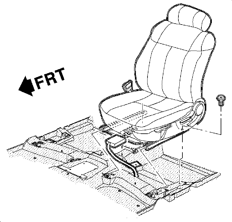
- Apply Loctite 242 Threadlocker, or equivalent to front seat attachment bolts.
- Install left front seat.
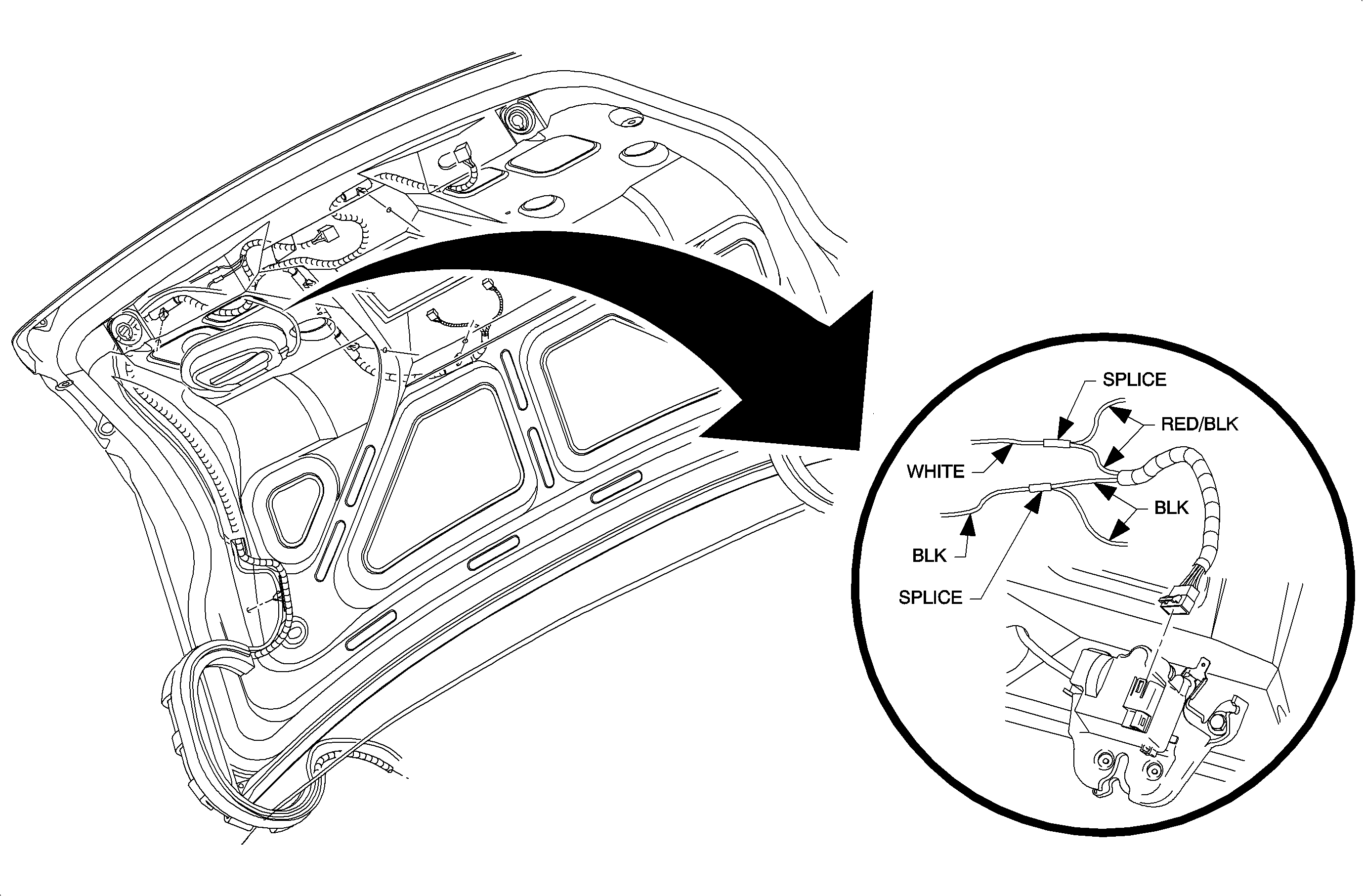
- Route BLK and WHT handle wires over to decklid latch area.
- Remove conduit on existing decklid wiring harness.
- Splice handle WHT wire to decklid latch harness RED/BLK wire using splice sleeve supplied with kit.
- Splice handle BLK wire to decklid latch harness BLK wire using splice sleeve supplied with kit.
- Install conduit onto decklid harness and BLK and WHT handle wires.
- Connect decklid harness to latch assembly.
- Tape all splices and conduit ends with electrical tape to prevent rattles and wire chaffing.
- Bundle and tape any excess WHT extension wire to existing vehicles harness.
- Install rear compartment side carpet.
- Connect negative battery cable.
Notice: Apply electrical tape to all wires to prevent damage due to sharp metal edges.
Remove left front seat attachment bolts and remove seat.
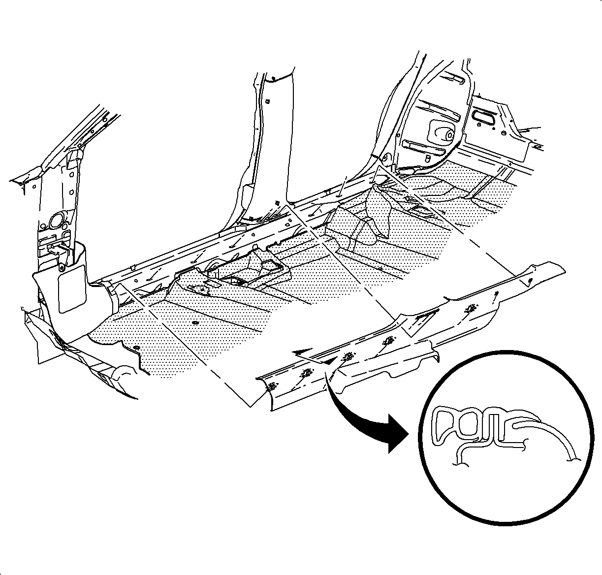
Right side shown, left side similar.
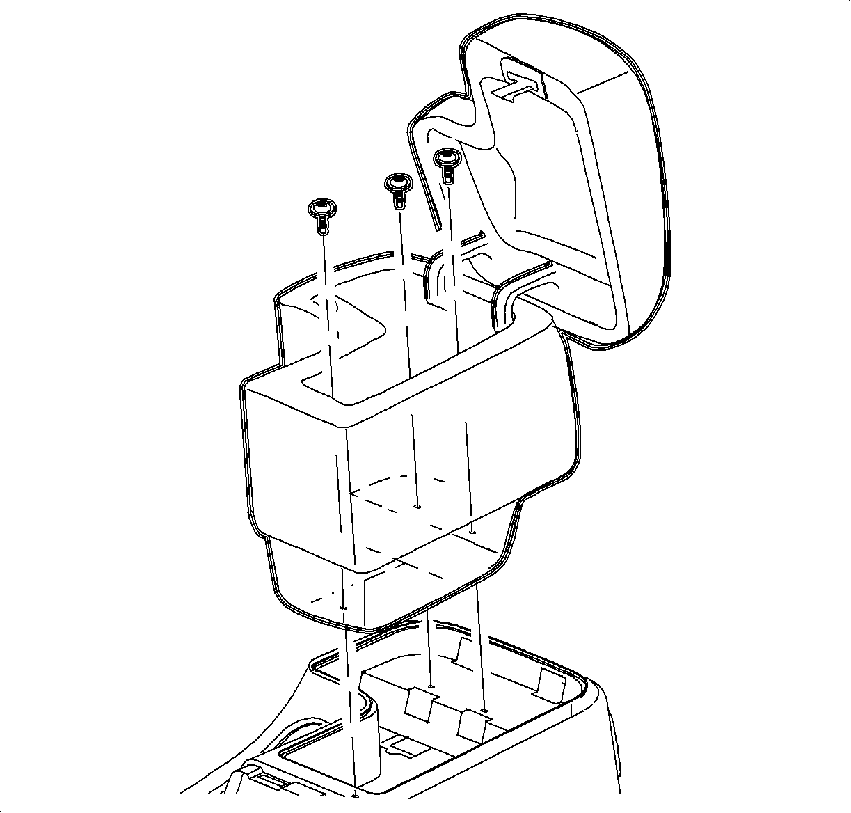
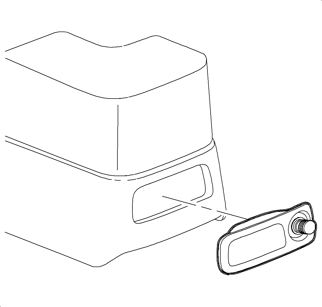
Important: The main power feed (ORN wire with WHT extension) for the truck interior release handle will be connected to the same wire as the auxiliary power outlet located in console.
The WHT extension wire supplied in kit will be spliced to the handle ORN wire to extend it and route up to the console area. The WHT extension wire will then be spliced to the ORN wire (ckt 1740) at auxiliary power outlet.
Notice: If equipped with leather seats, move rear seat cushion forward before removing rear seat bolster to prevent damage to leather. If seat is not leather, moving rear seat cushion is not necessary.
| • | Reach down into the outer corner of rear seat cushion to expose bolster retainer tab. |
| • | Bend rear seat bolster retainer tab upward. |
| • | Starting at bottom, pull forward to disengage bolster from retainer tab, then pull upward to disengage upper attachment. |
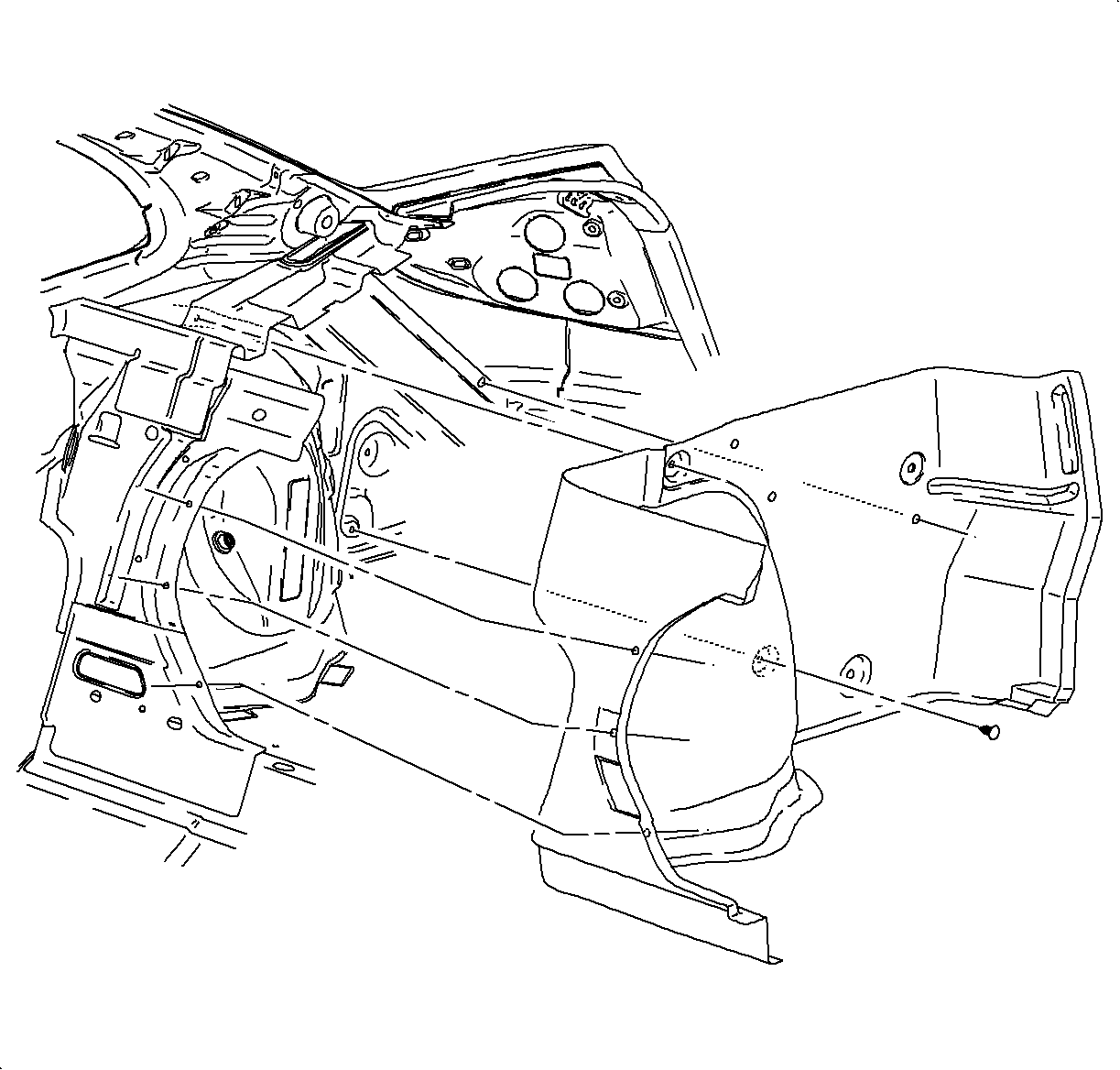
| • | Flip rear compartment floor carpet away from left side of vehicle. |
| • | Remove side carpet push pin retainers. |
| • | Remove rear compartment left side carpet. |
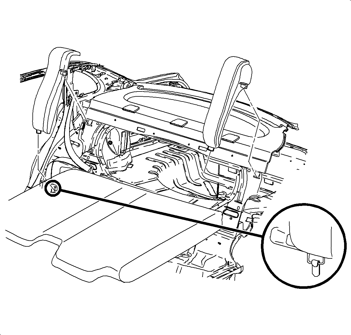
Caution: Make sure that rear seat shoulder belt is not caught behind bolster when installing.
Important: If leather rear seat cushion was moved, reposition or install seat cushion after installing rear seat bolster.
| • | Position rear seat bolster onto upper bolster attachment. |
| • | Push down on bolster to engage upper attachment. |
| • | Position bolster over lower retainer tab and bend lower retainer tab. |

Right side shown, left side similar.
| • | Position carpet retainer to vehicle. |
| • | Starting at rear of vehicle, slide carpet retainer under rear seat cushion. |
| • | Position carpet retainer over remaining attaching clip locations. |
| • | Gently pushing on attaching clips to install carpet retainer. |
| • | Install weatherstrip over carpet retainer using a flat blade tool. |

Tighten
Tighten the bolts to 25 N·m (19 lb in).
Important: After cutting decklid latch harness it will be necessary to splice three wires (two existing vehicle wires and one new handle wire) into each crimp and seal splice sleeve.
| • | Position rear compartment side carpet to vehicle. |
| • | Install push pin retainers that attach side carpet to vehicle. |
| • | Position rear compartment floor carpet back into place. |
Tighten
Tighten the cable to 17 N·m (13 lb ft).
System Functional Check
| • | Ensure new decklid latch is enabled only after two cycles of latch reset lever when decklid has been opened by the following methods: |
| - | Opened with key |
| - | Opened with vehicle interior lever |
| - | Opened with remote keyless entry (RKE) transmitter (if equipped) |
| • | Fold down rear seat backs and check the following: |
| - | Verify trunk interior release handle functions with decklid closed. |
| - | Ensure interior release handle LEDs illuminate and stay illuminated when decklid is closed and are not illuminated when decklid is open. |
Customer Demonstration and Owner's Handbook Insert
Supply customer with owner's handbook insert and use the insert to demonstrate function of Trap-Resistant Trunk Kit.
21019768 | Wiring - Fuse Holder and Connectors |
21019769 | Kit Asm - Decklid Latch |
Parts Description | Quantity | Model Usage |
|---|---|---|
Interior Release Handle | 1 | All |
Interior Release Handle Cable | 1 | All |
Interior Release Handle Fasteners | 4 | All |
Interior Release Handle Template | 1 | All |
Interior Release Handle Wiring Harness | 1 | All |
Trap-Resistant Latch Assembly | 1 | All |
Instruction Sheet | 1 | All |
Owner's Handbook Insert | 1 | All |
CLAIM INFORMATION
Customer Payment for Parts: Saturn will subsidize the cost of the parts by selling the kits at a reduced price. The Retailer will collect for the price of the Trap-Resistant Trunk Kit from the customer. Submit a claim using Labor Operations Code Z4024 without any labor hours, and enter the Manufacturer's Suggested Retail Price (MSRP) of the kit using case type "CP".
Reimbursement for Labor: The Retailer will be reimbursed for installation labor through the submission of a claim using the applicable case type of "VW" or "VP". Submit the claim using Labor Operation Code Z4024 for 1.4 hours.
Due to the nature of the installation, the procedure is not intended for the "do-it-yourselfer." It is in the customer's best interest to have the kit installed by an authorized Saturn Retail Facility. Therefore, Retailers should discourage over-the counter sales since the MSRP includes the installation.
All claims submitted must be supported by s signed Customer Service Order.
