SMU for Powertrain and Engine Service Manuals Regarding Evaporative Emission Flowcharts and EVAP Pressure/Purge Diagnostic Cart Test Procedure

| Subject: | Service Manual Update for Powertrain and Engine Service Manuals Regarding Evaporative Emission Flowcharts and EVAP Pressure/Purge Diagnostic Cart Test Procedure |
| Models: | 1998 - 2002 Saturn S-Series vehicles |
| 2000 - 2002 Saturn L-Series vehicles |
| 2002 Saturn VUE vehicles |
Purpose
The purpose of this bulletin is to update P0440, P0442, and P0455 evaporative emission flowcharts and EVAP Pressure/Purge Diagnostic Cart Test Procedure to reflect the use of new special tool J41750-A, Evaporative Emissions System Tester, which replaces J41750. Update the flowcharts and EVAP Pressure/Purge Diagnostic Cart Test Procedure in the following service manuals:
| • | All 1998/1999 Powertrain and 2000 - 2002 S-Series Engine Service Manuals. |
| • | All 2000, 2001, and 2002 L-Series (L61) and (L81) Engine Service Manuals. |
| • | All 2002 VUE Powertrain Electrical Diagnostic Service Manuals. |
Please obtain all service manuals indicated above at your location and make the necessary updates to each manual. Replace the service manual pages indicated in the tables with a copy of new DTC flowcharts or procedure page in this bulletin as indicated below.
- Using a marker or pen, cross out the items on the service manual (SM) pages indicated in the tables listed in this bulletin.
- On each item crossed out, write the following:
- Make copies of appropriate bulletin page and insert into service manuals as indicated in the tables.
"Refer to Technical Information Bulletin 01-T-02"
1998/1999 S-Series Powertrain Service Manuals | ||
|---|---|---|
Flowchart/Procedure To Be Replaced | SM Page | Replace With Bulletin Page |
EVAP Pressure/Purge Diagnostic Cart Test Procedure | 193 | 8 |
DTC P0440 | 195 | 4 |
DTC P0442 | 197 | 5 |
2000 - 2002 S-Series Engine Service Manuals | ||
Flowchart/Procedure To Be Replaced | SM Page | Replace With Bulletin Page |
DTC P0440 | 235 | 4 |
DTC P0442 | 237 | 5 |
EVAP Pressure/Purge Diagnostic Cart Test Procedure | 343 | 8 |
200 L-Series (L61) Engine Service Manuals | ||
|---|---|---|
Flowchart/Procedure To Be Replaced | SM Page | Replace With Bulletin Page |
DTC P0440 | 207 | 6 |
DTC P0442 | 209 | 7 |
EVAP Pressure/Purge Diagnostic Cart Test Procedure | 322 | 8 |
2001 L-Series (L61) Engine Service Manuals | ||
Flowchart/Procedure To Be Replaced | SM Page | Replace With Bulletin Page |
DTC P0440 | 207 | 6 |
DTC P0442 | 209 | 7 |
EVAP Pressure/Purge Diagnostic Cart Test Procedure | 328 | 8 |
2002 L-Series (L61) Engine Service Manuals | ||
Flowchart/Procedure To Be Replaced | SM Page | Replace With Bulletin Page |
DTC P0440 | 225 | 6 |
DTC P0442 | 229 | 7 |
EVAP Pressure/Purge Diagnostic Cart Test Procedure | 340 | 8 |
New Flowchart To Be Replaced | Location To Insert New Flowchart |
|---|---|
DTC P0442 | Insert bulletin page 7 between 300 and 301. |
DTC P0455 | Insert bulletin page 6 between 322 and 323. |
2001 L-Series (L81) Engine Service Manuals | |
New Flowchart To Be Replaced | Location To Insert New Flowchart |
DTC P0442 | Insert bulletin page 7 between 306 and 307. |
DTC P0455 | Insert bulletin page 6 between 326 and 327. |
2002 L-Series (L81) Engine Service Manuals | ||
|---|---|---|
Flowchart/Procedure To Be Replaced | SM Page | Replace With Bulletin Page |
DTC P0442 | 323 | 7 |
DTC P0455 | 350 | 6 |
EVAP Pressure/Purge Diagnostic Cart Test Procedure | 455 | 8 |
2002 VUE Powertrain Electrical Diagnostic Service Manuals | ||
|---|---|---|
Flowchart/Procedure To Be Replaced | SM Page | Replace With Bulletin Page |
DTC P0440 (L61) | 145 | 4 |
DTC P0442 (L61) | 149 | 5 |
EVAP Pressure/Purge Diagnostic Cart Test Procedure | 294 | 8 |
DTC P0440 (L81) | 574 | 4 |
DTC P0442 (L81) | 579 | 5 |
EVAP Pressure/Purge Diagnostic Cart Test Procedure | 739 | 8 |
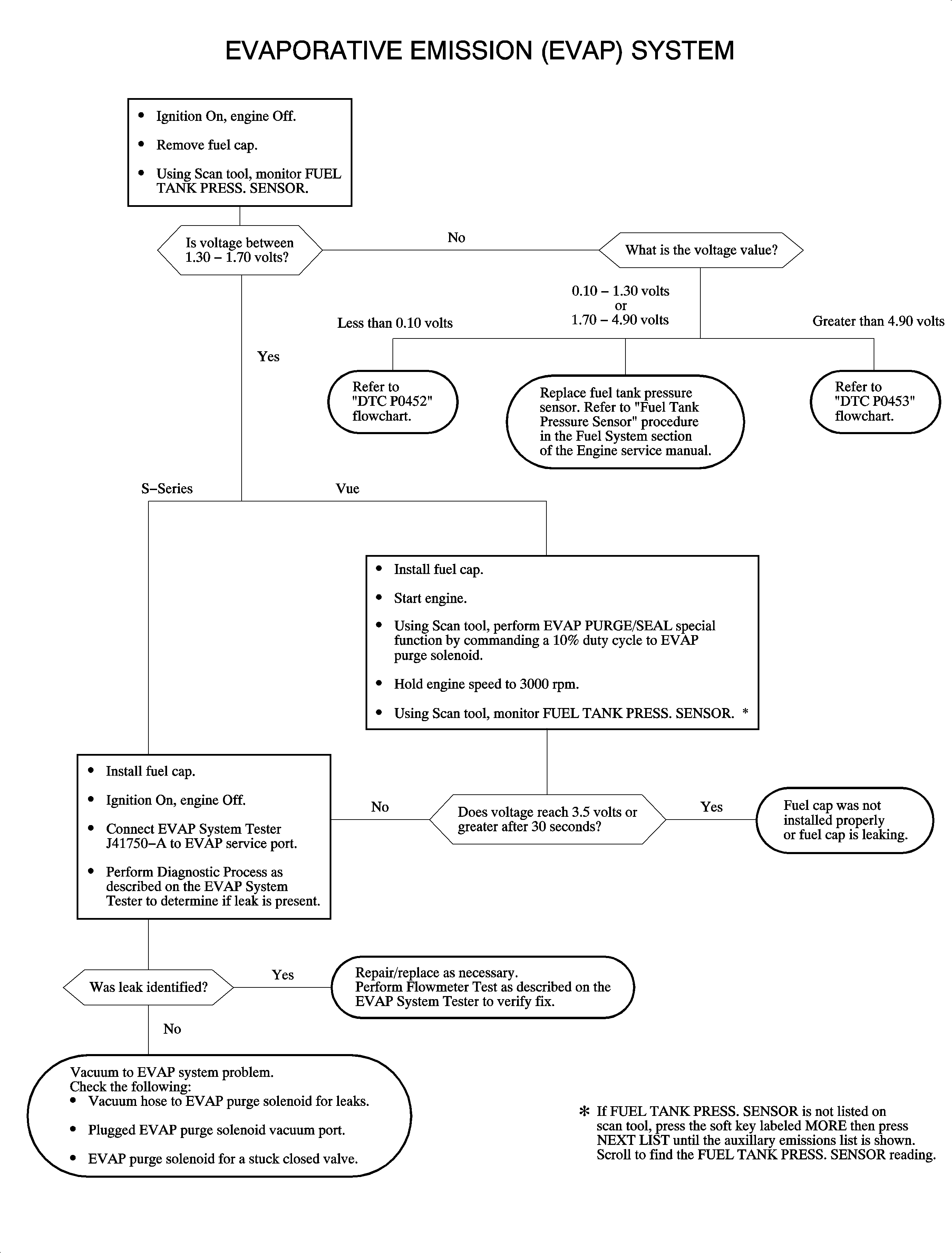
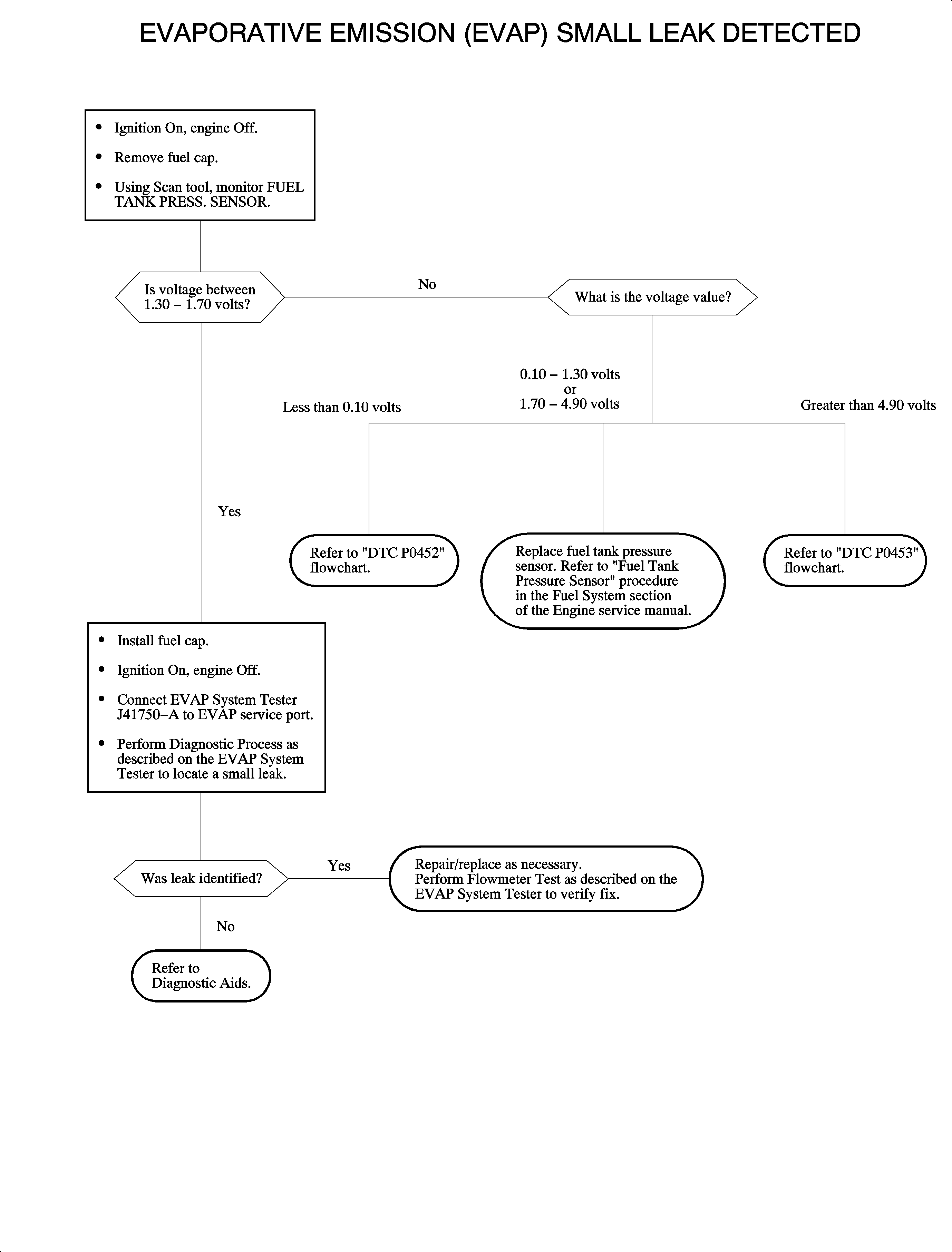
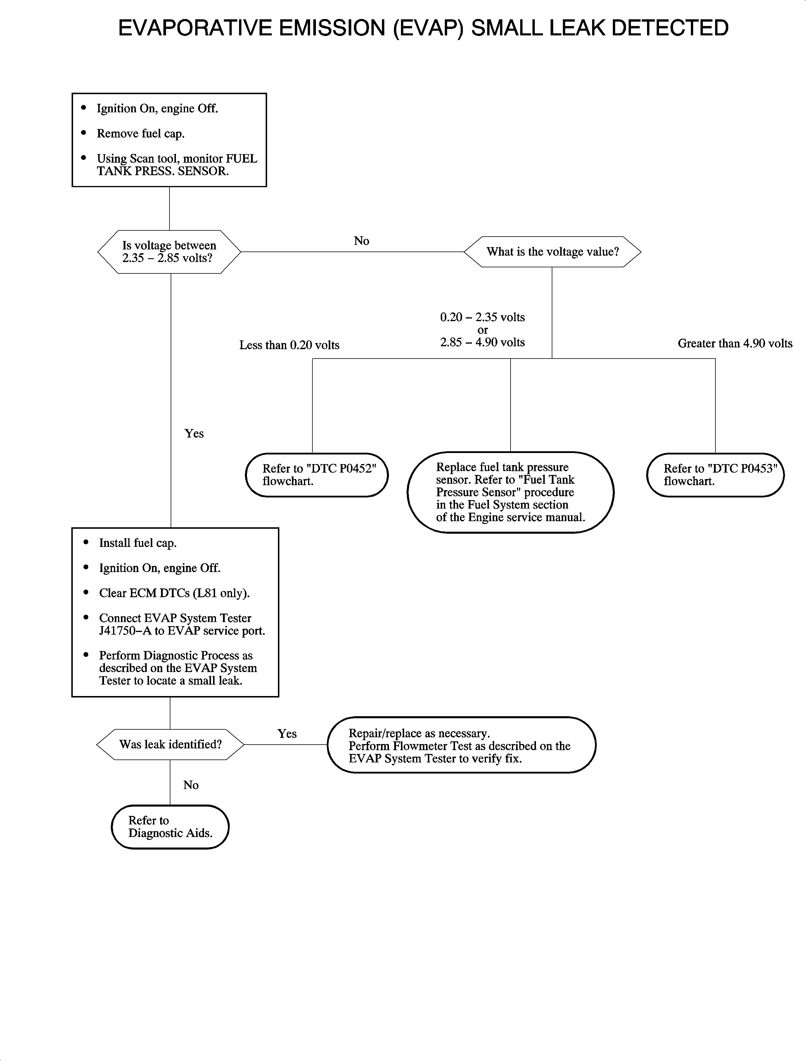
Service manual update page for DTC P0440 flowchart. Refer to Technical Information Bulletin 01-T-02, January 2002.

Service manual update page for DTC P0442 flowchart. Refer to Technical Information Bulletin 01-T-02, January 2002.

Service manual update page for DTC P0440 and P0455 flowchart. Refer to Technical Information Bulletin 01-T-02, January 2002.

Service manual update page for DTC P0442 flowchart. Refer to Technical Information Bulletin 01-T-02, January 2002.

Service manual update for EVAP Pressure/Purge Diagnostic Cart Test Procedure. Refer to Technical Information Bulletin 01-T-02, December 2001.
EVAPORATIVE EMISSIONS SYSTEM LEAK TEST
Diagnostic Process
ENSURE THAT VEHICLE UNDERBODY TEMPERATURE IS SIMILAR TO AMBIENT TEMPERATURE, AND ALLOW SURROUNDING AIR TO STABILIZE BEFORE STARTING DIAGNOSTIC PROCEDURE.
- Ignition ON, engine OFF. Seal EVAP system using scan tool.
- Connect Evaporative Emission System Tester (EEST) red battery clip to positive (+) battery terminal. Connect black battery clip to chassis ground.
- Connect EEST's nitrogen/smoke hose onto EVAP service port. Refer to appropriate service manual for EVAP service port location.
- Turn NITROGEN/SMOKE valve to SMOKE.
- Inject smoke into EVAP system.
- Verify smoke has filled EVAP system by removing gas cap. Smoke is visible leaving fuel fill pipe when system is full. Reinstall gas cap. Introduce smoke for 60 additional seconds.
- Use a high intensity white light (J41413-SPT) to inspect entire EVAP system for exiting smoke. Induce smoke at 15 second intervals, as needed, until leak source is identified. If leak source is not identified, go to Verification Process.
Verification Process
FLOWMETER TEST
Models | 1998-1999 MY | 2000 MY | 2001 MY | 2002 MY |
S-Series | .040 in | .040 in | .020 in | .020 in |
L-Series | N/A | .040 in | .040 in | .020 in |
VUE | N/A | N/A | N/A | .040 in |
- Turn NITROGEN/SMOKE valve to NITROGEN.
- Disconnect nitrogen/smoke hose from EVAP service port.
- Connect hose to correct test orifice on bottom-front of EEST. Refer to the above chart:
- Use remote switch to activate EEST.
- Align red flag on flowmeter with floating indicator. Use remote switch to deactivate EEST.
- Remove hose from test orifice; reinstall onto EVAP service port.
- Ignition ON, engine OFF. Seal EVAP system using a scan tool.
- Activate nitrogen flow and fill the system. Watch floating indicator until it stabilizes and stops dropping.
- Compare flowmeter's stable floating indicator position to red flag. If indicator floats:
Important: Larger volume fuel tanks, and/or those with lower fuel levels, may require several minutes for floating indicator to stabilize.
| • | ABOVE red flag - UNACCEPTABLE (FAIL-return to service information). |
| • | BELOW red flag - ACCEPTABLE (PASS-test completed). |
SERVICE BAY TEST
Disconnect nitrogen/smoke hose from vehicle. Install service port cap. Perform EVAP Service Bay Test using a scan tool.
| • | If vehicle passes Service Bay Test, testing is complete. |
| • | If vehicle does not pass, return to service information. |
