For 1990-2009 cars only
Tools Required
J 39400-A Halogen Leak Detector
Removal Procedure
- Recover the refrigerant. Refer to Refrigerant Recovery and Recharging .
- Remove injector sight shield.
- Remove right engine mount strut. Refer to Engine Mount Strut Replacement - Right Side
- Remove underhood electrical center. Refer to Underhood Electrical Center or Junction Block Replacement
- Remove underhood electrical center bracket.
- Reposition wiring harness as required.
- Remove front bumper upper facia support. Refer to Front Bumper Fascia Upper Support Replacement
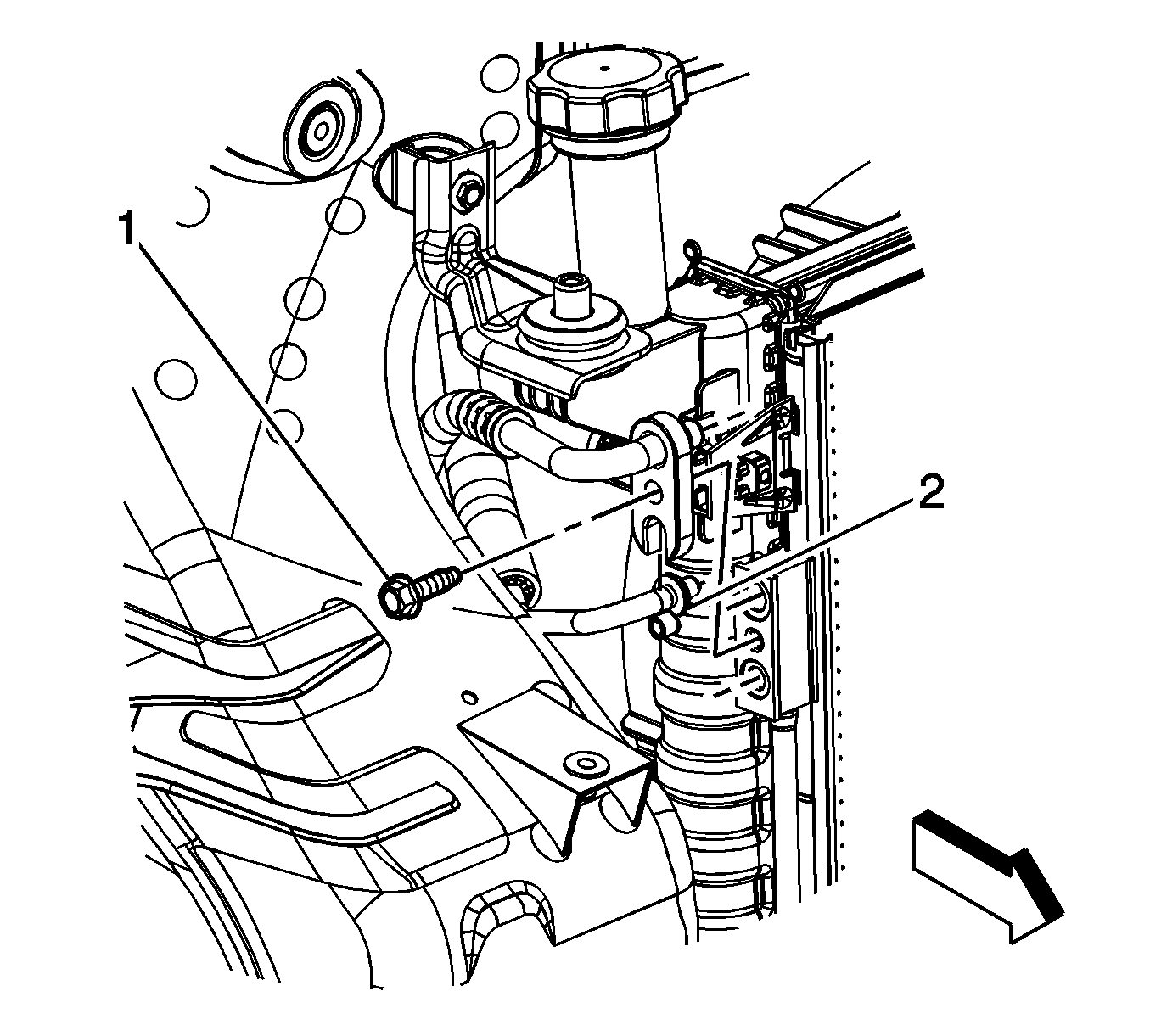
- Remove the liquid line bolt from the A/C condenser (1).
- Disconnect the liquid line from the A/C condenser (2).
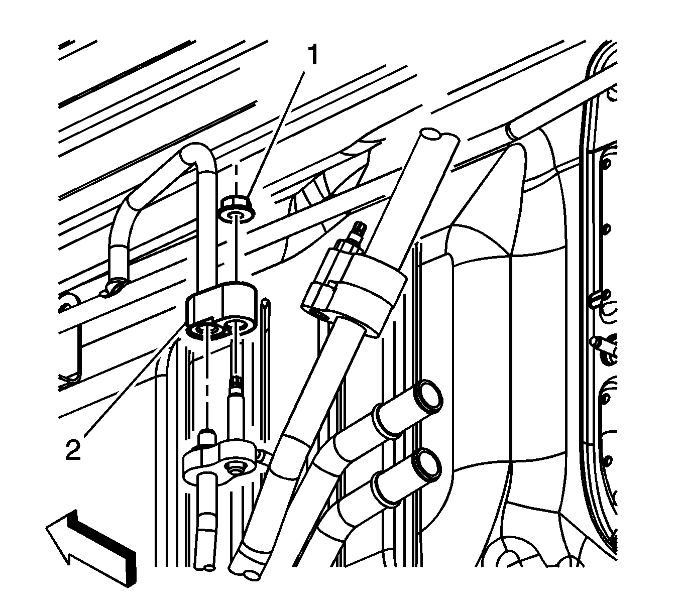
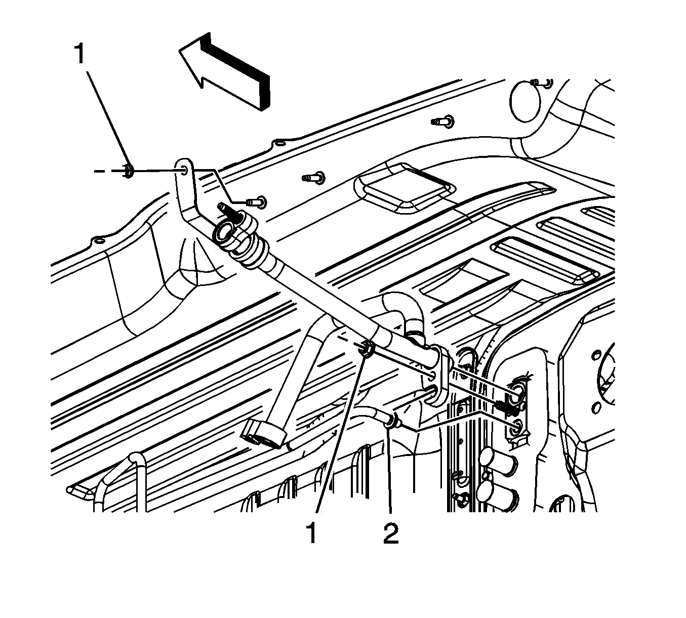
- Remove the liquid line to auxiliary tube nut (1).
- Remove TXV tube retainer nut (1).
- Disconnect the liquid line (2) and evaporator hose/tube from the TXV at plenum panel.
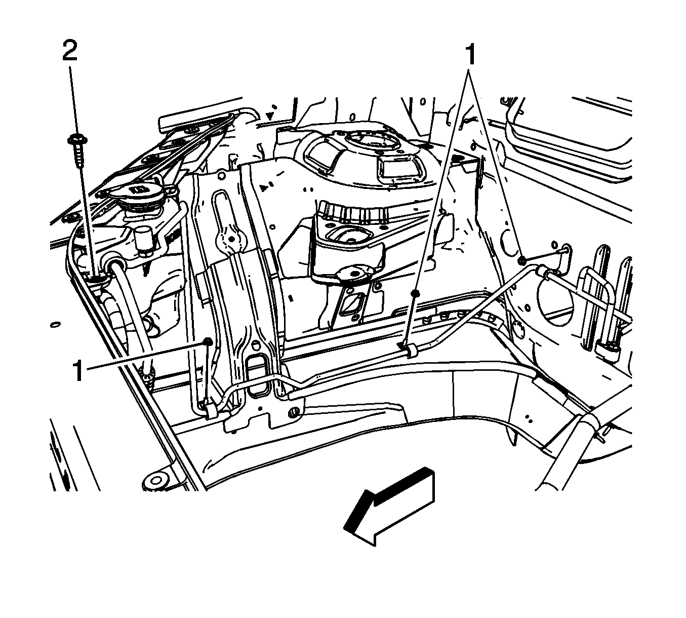
- Remove the attaching liquid line clamp nuts along right inner frame rail and plenum panel (1).
- Remove the liquid line bracket bolt at right side of upper tie bar support (2).
- Remove the liquid line.
- Remove and discard the discharge line sealing washer.


Installation Procedure
- Install new sealing washers to the liquid line. Refer to Sealing Washer Replacement .
- Connect the liquid line (2) and evaporator hose/tube to the TXV at plenum panel.
- Install the liquid line to TXV nut (1).
- Connect the liquid line to the auxiliary evaporator tube.
- Install the liquid line nut (1).
- Install the liquid line to the condenser (2).
- Install the liquid line nut (1).
- Install liquid line bracket bolt to upper tie bar support (2).
- Install the liquid line bracket nuts along frame rail and plenum panel (1).
- Install underhood electrical center bracket.
- Install underhood electrical center. Refer to Underhood Electrical Center or Junction Block Replacement
- Install front bumper upper facia support. Refer to Front Bumper Fascia Upper Support Replacement
- Install right engine mount strut. Refer to Engine Mount Strut Replacement - Right Side
- Install injector sight shield.
- Evacuate and recharge the refrigerant system. Refer to Refrigerant Recovery and Recharging .
- Leak test the fittings of the component using J 39400-A .

Notice: Refer to Fastener Notice in the Preface section.
Tighten
Tighten the bolt to 9 N·m (80 lb in).

Tighten
Tighten the bolt to 9 N·m (80 lb in).

Tighten
Tighten the bolt to 9 N·m (80 lb in).

Tighten
Tighten the bolt to 9 N·m (80 lb in).
Tighten
Tighten the bolt to 4 N·m (35 lb in).
