Ambient Air Temperature Sensor Display in Instrument Panel Cluster (IPC) Inaccurate or Reads Too High (Reposition Ambient Air Temperature Sensor and Reprogram HVAC Control Module)

| Subject: | Ambient Air Temperature Sensor Display In Instrument Panel Cluster (IPC) Inaccurate Or Reads Too High (Reposition Ambient Air Temperature Sensor And Reprogram HVAC Control Module) |
| Models: | 2007-2008 GMC Acadia |
| 2007-2008 Saturn OUTLOOK |
Condition
Some customers may comment that the ambient temperature display is inaccurate or reads too high.
Correction
Technicians are to relocate the ambient air temperature sensor to a new location and reprogram the Heating Ventilation And Air Conditioning (HVAC) Control Module using the following procedure:
- Open the hood.
- Remove the front compartment sight shield. Refer to the Front Compartment Sight Shields Replacement procedure in SI.
- Disconnect the wiring harness to the ambient air temperature sensor. Remove the ambient air temperature sensor. Refer to the Ambient Air Temperature Sensor Replacement procedure in SI.
- Remove both front tire and wheel assemblies. Refer to the Tire and Wheel Removal and Installation procedure in SI.
- Remove both front wheelhouse liners. Refer to the Front Wheelhouse Liner Replacement (Front) procedure in SI.
- Disconnect the wiring harness to both front fog lights.
- Remove the front bumper fascia. Refer to the Front Bumper Fascia Replacement procedure in SI.
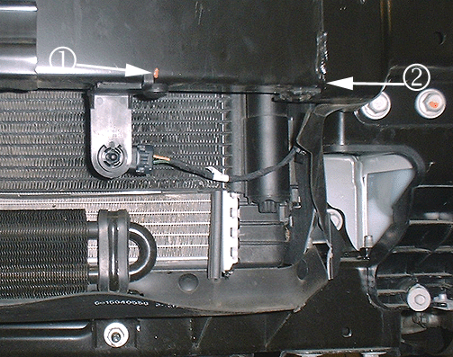
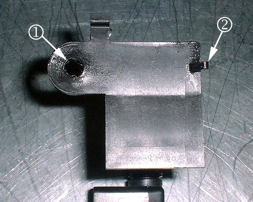
- Hold the new ambient air temperature sensor in position on the front bumper beam as shown in the illustration above. Measure 145 mm (5¾ in) from the edge of the bumper beam bracket (callout 2 above) to the locating pin on the sensor bracket (callout 1 above). Mark the front bumper beam next to the locating pin on the ambient air temperature sensor bracket with a paint pen as shown at callout 1.
- Hold the ambient air temperature sensor on the front bumper bar at the previously marked position and use a center punch to mark the location for the guide pin hole (callout 2 in the illustration above). Drill a 6.5 mm (¼ in) hole in the front bumper beam for the guide pin.
- Insert the sensor bracket guide pin into the hole. Hold the new ambient air temperature sensor in position and use a center punch to mark the hole location (at callout 1 above) for the sensor retaining Push Pin, P/N 11589290. Drill a 6.5 mm (¼ in) hole for the push pin.
- Apply Synthetic Lubricant with Teflon, P/N 12371287 (in Canada, 10953437), or equivalent, to the holes in the front bumper beam for rust prevention.
- Apply a piece of two-sided tape to the top of the ambient air temperature sensor bracket. This will help retain the new ambient air temperature sensor.
- Install the new ambient air temperature sensor onto the front bumper beam.
- Cut the connector from the end of the wiring harness for the ambient air temperature sensor.
- Splice the Ambient Air Temperature Sensor Jumper Harness, P/N 25925947 onto the wiring harness using two wire splices, P/N 19168446.
- Route the jumper harness down along the left side of the radiator assembly to the new ambient air temperature sensor location. Use wire ties to secure the jumper harness as necessary. Make sure that the jumper harness is secured away from the engine cooling fan. Connect the jumper harness to the ambient air temperature sensor.
- Install the front bumper fascia.
- Install the front wheelhouse liners.
- Install the front tire and wheel assemblies.
- Install the front compartment sight shield.
- Close the hood.
- Reprogram the HVAC Control Module with the latest software available on TIS2WEB. Refer to the HVAC Control Module Programming and Setup procedure in SI for more information.
- Verify proper operation of the ambient air temperature sensor.
Important: Be careful to make the proper selection from the list of available calibrations. Verify the RPO Codes. New calibrations are available for vehicles with or without the ambient air temperature sensor being relocated.
Parts Information
Part Number | Description | Qty |
|---|---|---|
11589290 | Push Pin (Fits 6.5 Hole, 4.5-7.0 Panel Thickness) | 1 |
12371287 (in Canada 10953437) | Synthetic Lubricant with Teflon | 1 |
15880715 | Ambient Air Temperature Sensor With Bracket | 1 |
19168446 | Splice Sleeve (Salmon Colored) | 2 |
25925947 | Forward Lamp Wiring Harness Jumper | 1 |
Warranty Information
For vehicles repaired under warranty, use:
Labor Operation | Description | Labor Time |
|---|---|---|
D9741* | Reposition Ambient Air Temperature Sensor and Reprogram HVAC Control Module | 1.4 hrs |
*This labor operation number is for bulletin use only. This number will not be published in the Labor Time Guide. | ||
