For 1990-2009 cars only
Removal Procedure
Important: In the following service procedures, the left side is shown, the right side is similar.
- Remove the tire and wheel assembly. Refer to Tire and Wheel Removal and Installation .
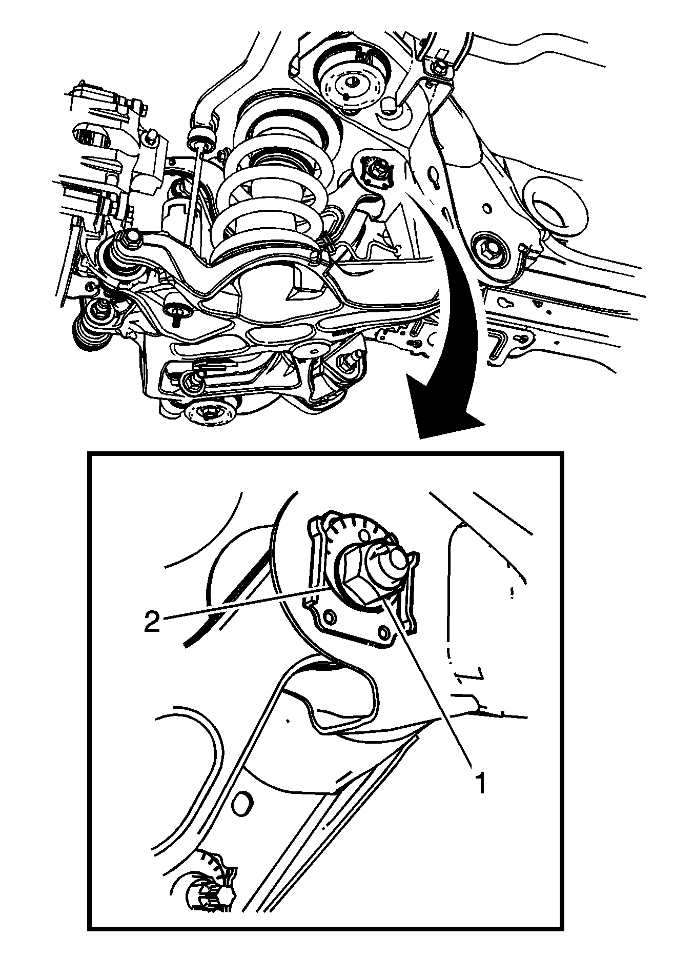
- Scribe a reference mark on the adjuster cam and the bracket to aid in installing the upper control arm.
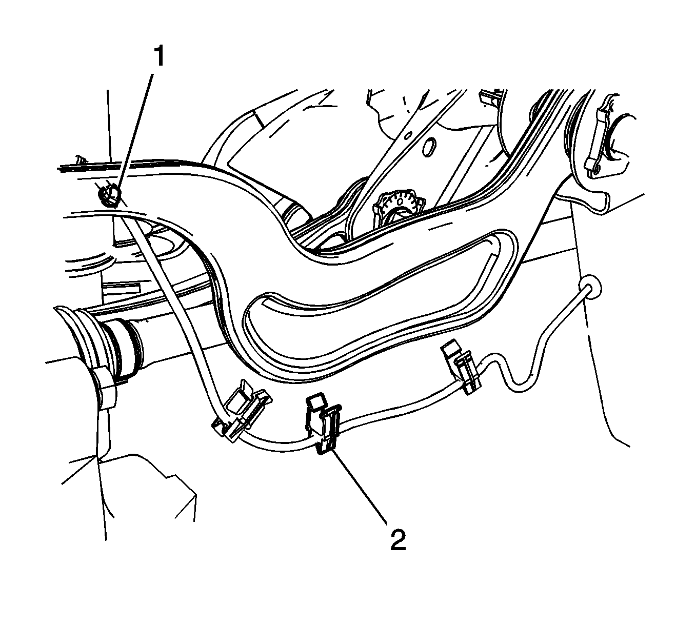
- Remove the speed sensor wiring harness retaining clips (1) and (2) from the upper control arm.
- Position a jack stand under the lower control arm.
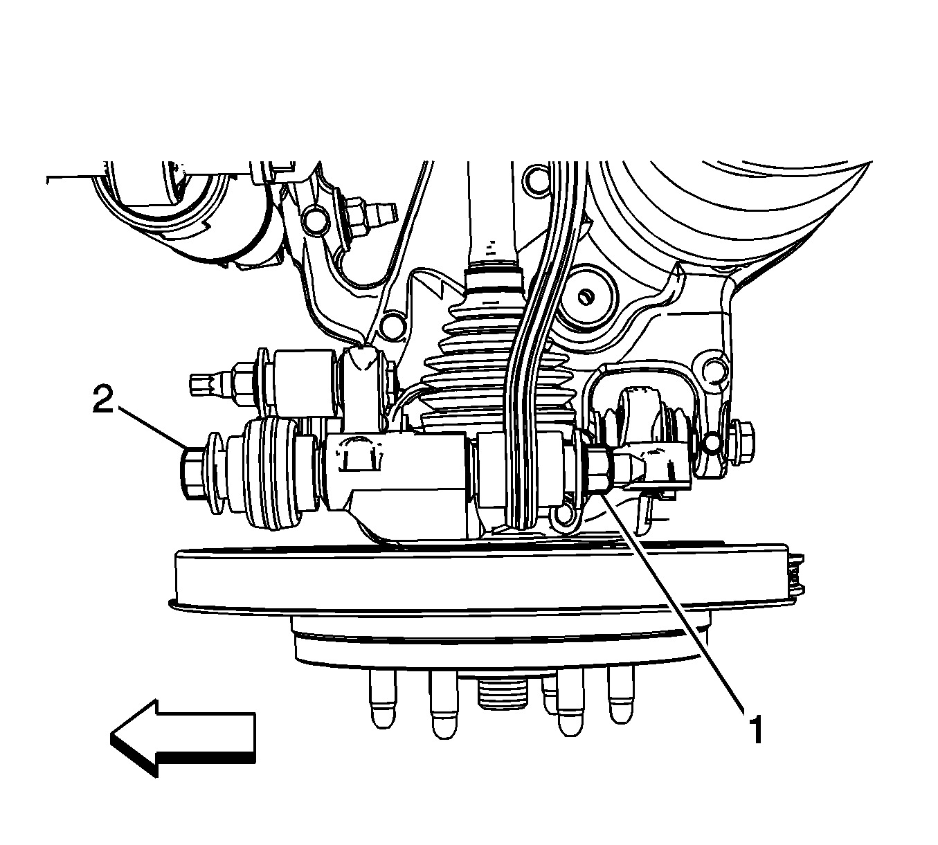
- Remove the upper control arm mounting nut (1) and bolt (2).
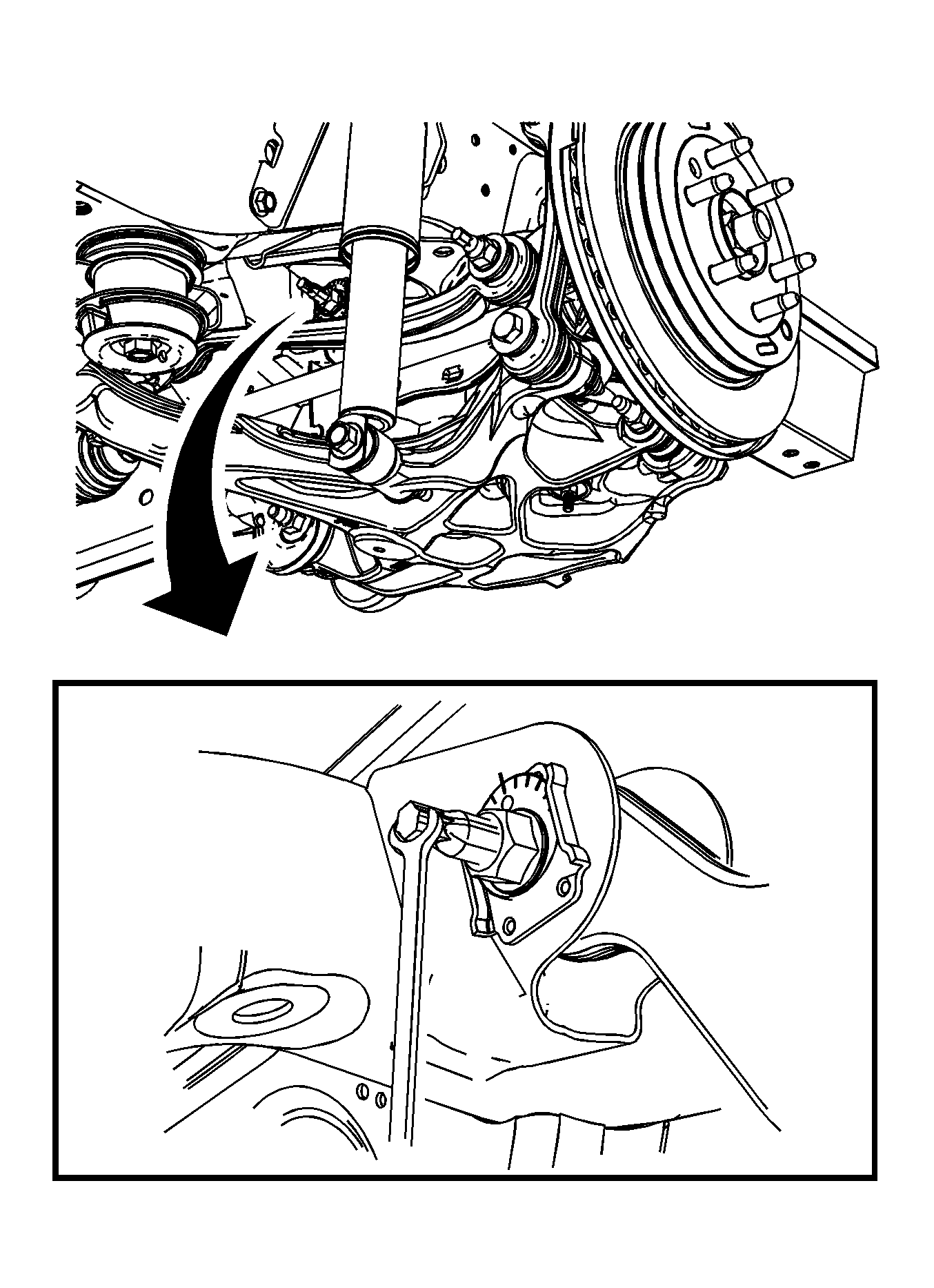
- Use a wrench to hold the adjuster cam bolt.
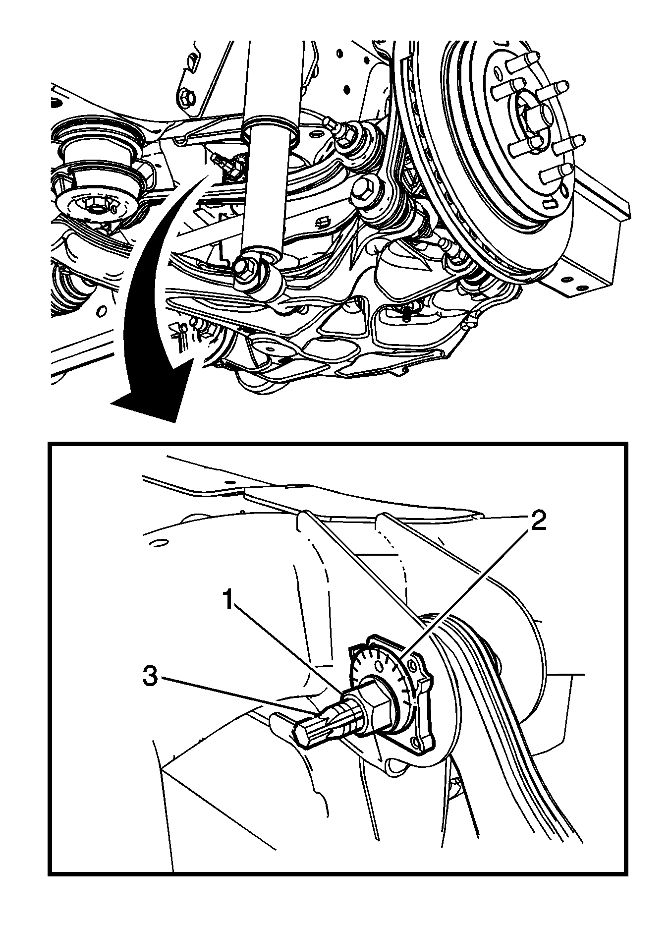
- Remove the rear upper adjuster cam bolt (1).
- Remove the rear upper adjuster cam (2).
- Remove front the adjuster cam nut (1).
- Remove the adjuster cam (2).
- Remove the adjuster cam bolt (3).
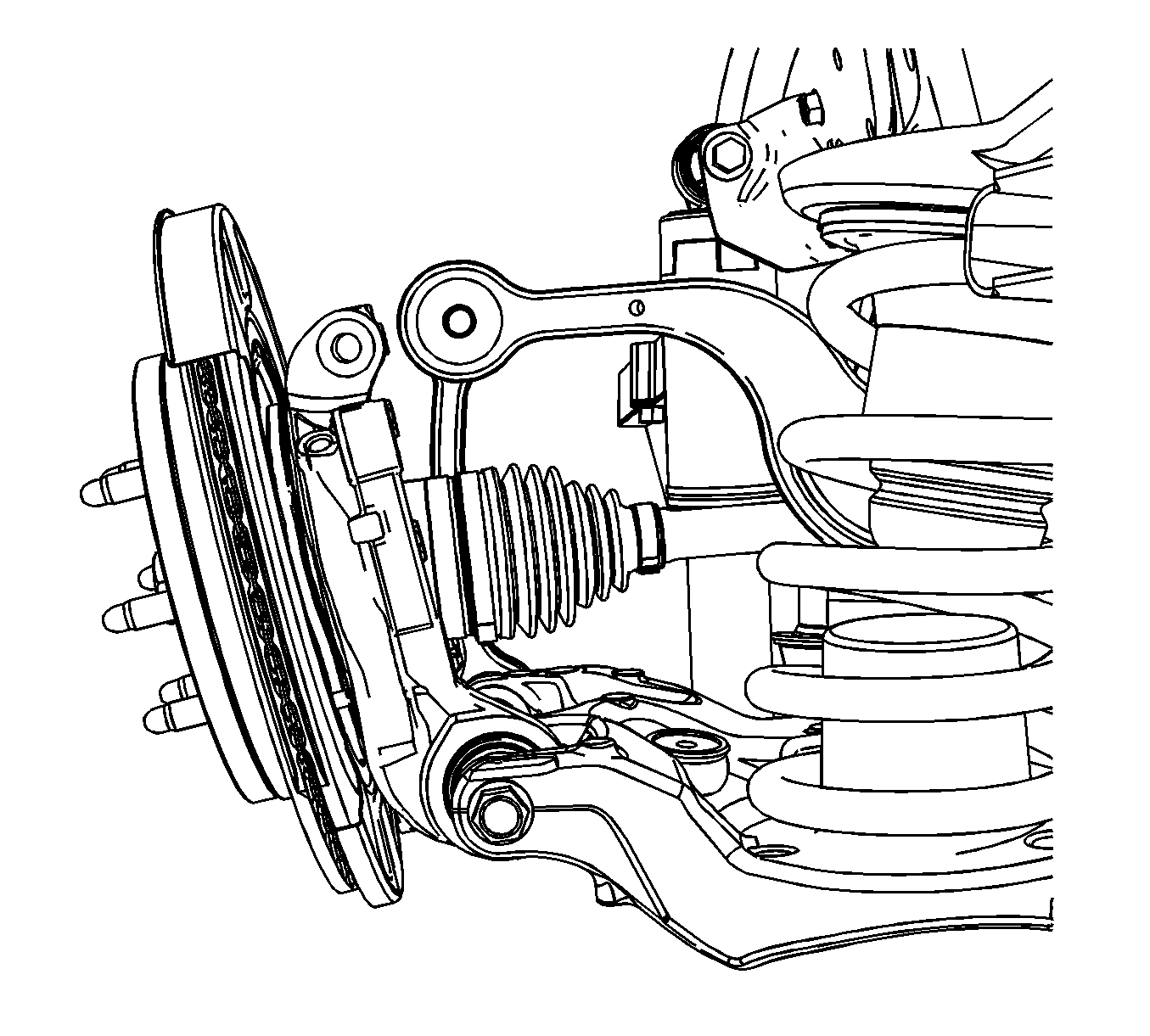
- Rotate the rear knuckle down to gain removal clearance for the upper control arm.
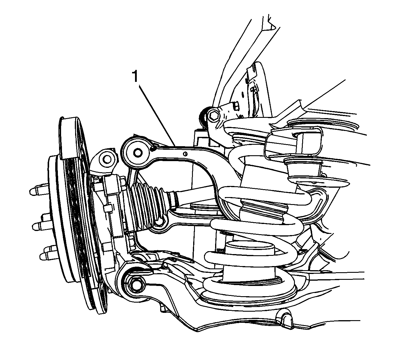
- Remove the upper control arm (1).
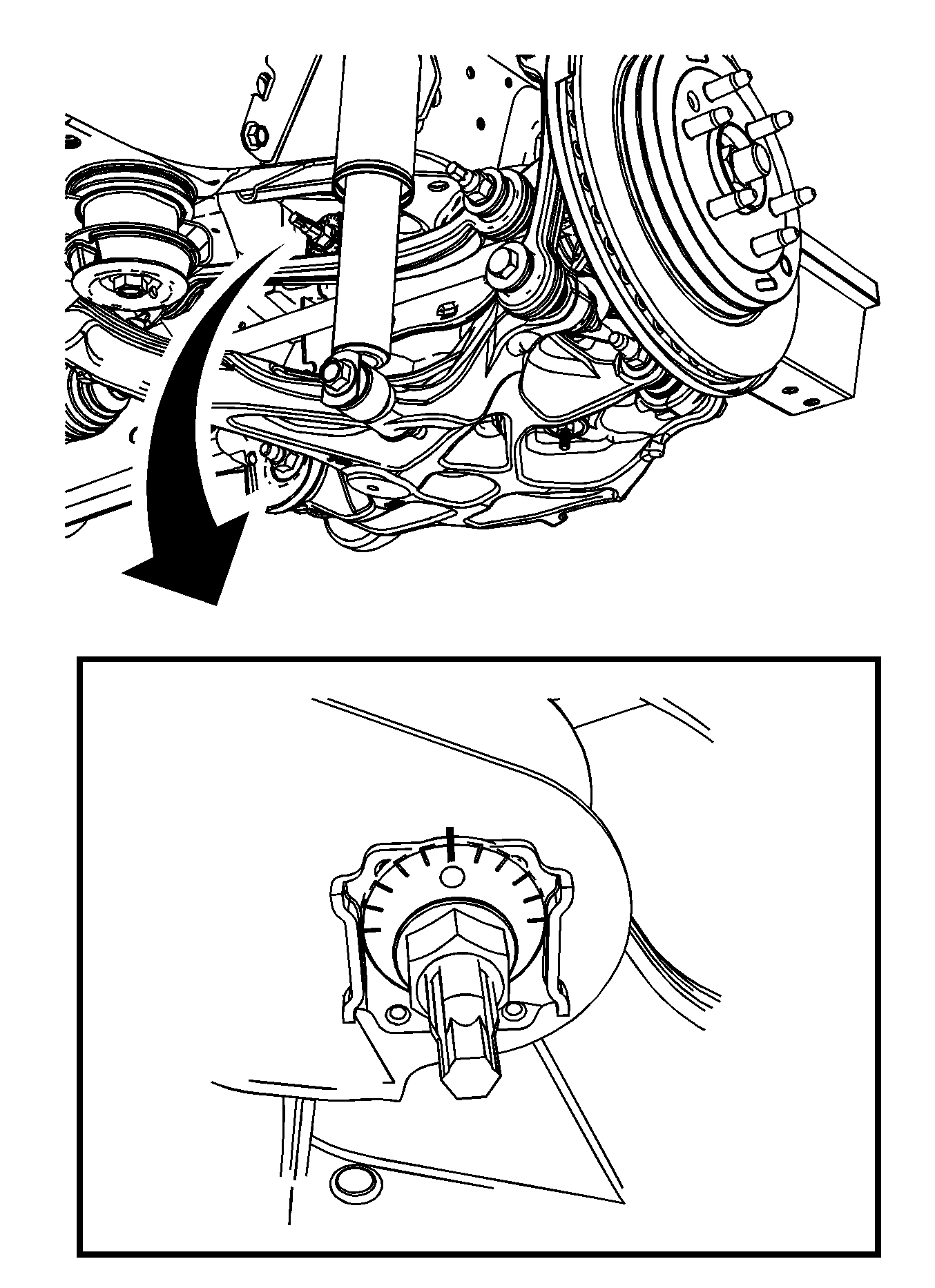
Important: If removing the upper control arm to service scribe a line on the front adjuster cam to aid in the realignment of the control arm.
Installation Procedure
- Install the upper control arm (1) in the mounting bracket.
- Rotate the knuckle assembly back into the proper position.
- Position the front adjuster cam (2) in the mounting bracket.
- Install the adjuster cam bolt (3).
- Finger tighten the front adjuster cam nut (1).
- Position the rear adjuster cam (2) in the mounting bracket.
- Finger tighten the rear adjuster cam nut (1).
- Install the upper control arm bolt (2) and nut (1).
- Remove the jack stand from under the lower control arm.
- Install the speed sensor wiring harness retaining clips (1) and (2) on the upper control arm.
- Align the reference marks on the adjuster cam and bracket.
- Using a wrench to hold the adjuster cam bolt in place, tighten all the adjuster cam nuts.
- Install the tire and wheel assembly. Refer to Tire and Wheel Removal and Installation .
- Verify wheel alignment. Refer to Wheel Alignment Specifications .


Notice: Refer to Fastener Notice in the Preface section.

Tighten
Tighten the bolt to 100 N·m (74 lb ft) plus 90 degrees.


Tighten
Tighten the nuts to 140 N·m (103 lb ft).
