Removal Procedure
- Raise and support the vehicle. Refer to Lifting and Jacking the Vehicle .
- Remove the rear wheel bearing and hub. Refer to Rear Wheel Bearing and Hub Replacement .
- Remove the park brake backing plate assembly. Refer to Rear Parking Brake Anchor Backing Plate Replacement .
- Remove the rear wheel drive shaft. Refer to Rear Wheel Drive Shaft and Rear Axle Shaft Seal Replacement .
- Position a jack stand under the lower control arm.
- Remove the nut from the bolt from the knuckle to the adjuster link.
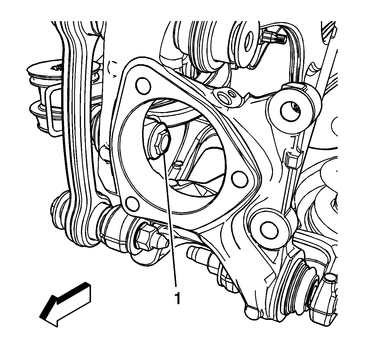
- Remove the bolt (1) from the knuckle to the adjuster link.
- Remove the lower knuckle to lower control arm nut and bolt.
- Remove the bolt and nut from the upper control arm to the knuckle.
- Remove the knuckle from the upper and lower control arms.
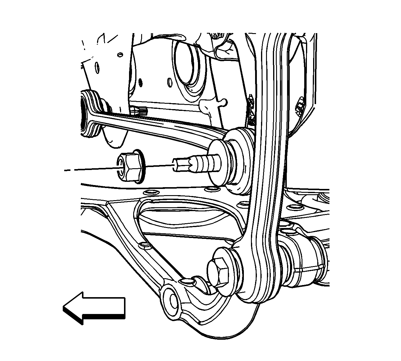
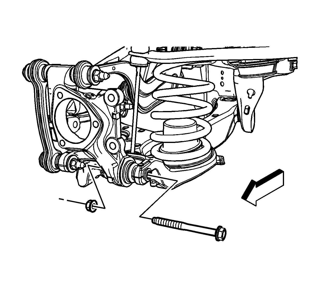
Important: If removing the lower nut and bolt in step 8 or the upper nut and bolt in step 9, to service other suspension components, it is not necessary to remove the knuckle.
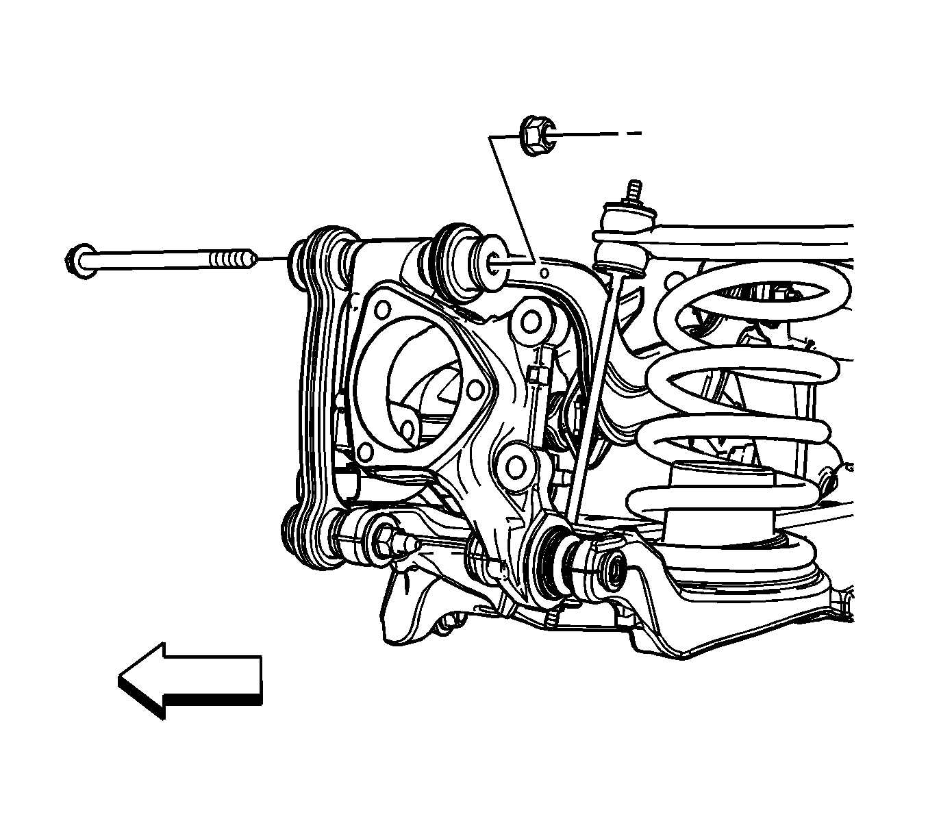
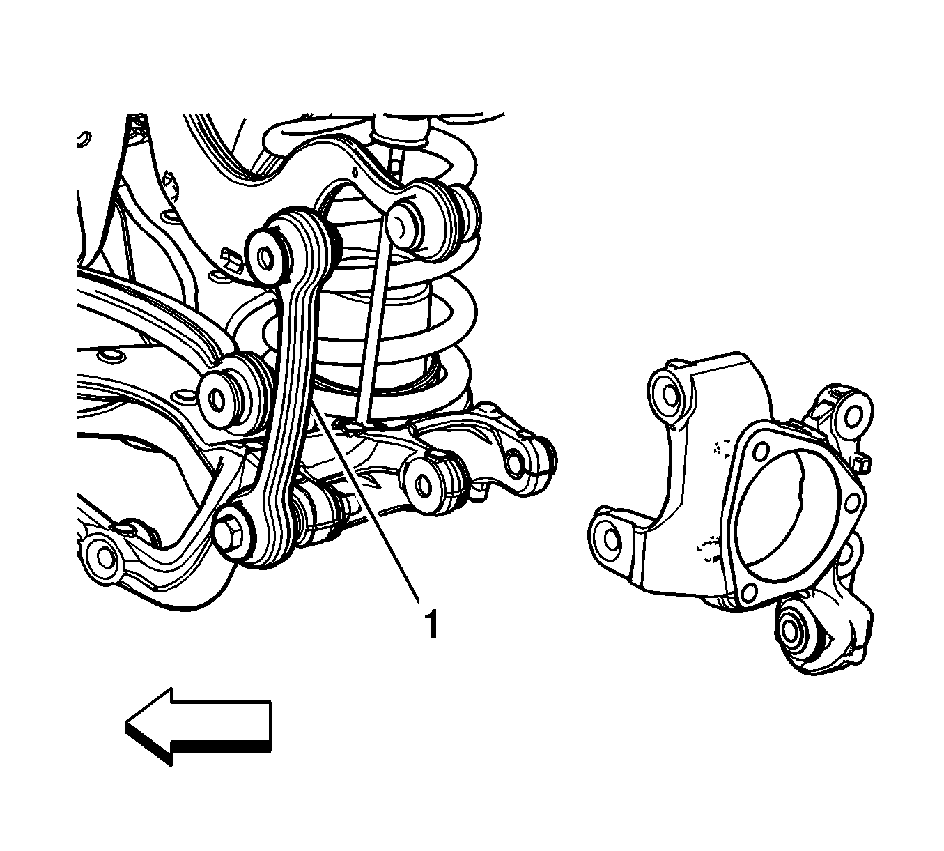
Important: In the following service procedure, it is not necessary to remove the rear suspension link from the lower control arm. The link (1) can remain attached to the lower control arm.
Installation Procedure
Important: In steps 2-5, ensure that all the fasteners are installed loose in order to allow movement in the knuckle to allow for alignment all the mounting holes. After all the fasteners have been installed, then the proper torque specifications can be applied.
- Position the knuckle in the upper and lower control arms.
- Install the bolt (1) from the knuckle to the adjuster link.
- Finger tighten the nut for the bolt from the knuckle to the adjuster link.
- Install the bolt from the upper control arm to the knuckle and finger tighten the nut.
- Install the bolt from the lower control arm to the knuckle and finger tighten .
- Remove the jack stand from under the lower control arm.
- Install the rear wheel drive shaft. Refer to Rear Wheel Drive Shaft and Rear Axle Shaft Seal Replacement .
- Install the park brake backing plate assembly. Refer to Rear Parking Brake Anchor Backing Plate Replacement .
- Install the rear wheel bearing and hub. Refer to Rear Wheel Bearing and Hub Replacement .
- Remove the support and lower the vehicle.
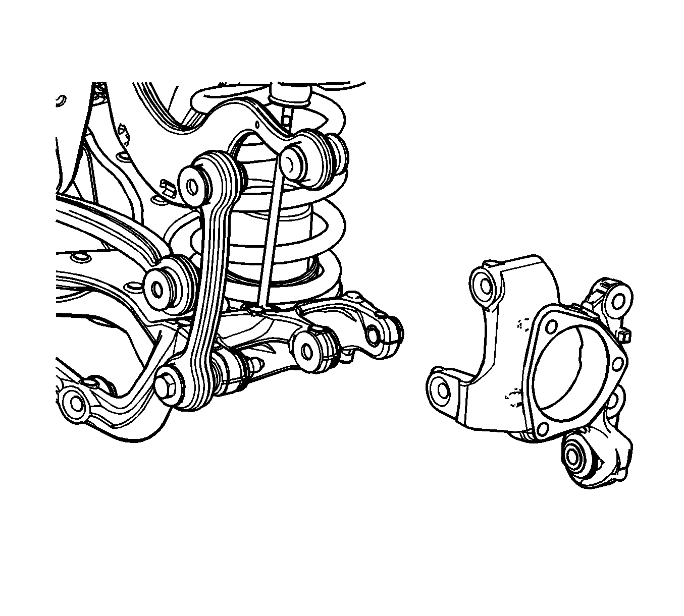

Notice: Refer to Fastener Notice in the Preface section.

Tighten
Tighten the nut to 75 N·m (55 lb ft) plus 60 degrees.

Tighten
Tighten the bolt to 100 N·m (74 lb ft) plus 60 degrees.

Tighten
Tighten the bolt to 100 N·m (74 lb ft) plus 60 degrees.
