Tools Required
J-39580 Engine Support Stand
Removal Procedure
- Install the engine support fixture. Refer to Engine Support Fixture.
- Raise and support the vehicle. Refer to Lifting and Jacking the Vehicle.
- Remove the front tires and wheels. Refer to Tire and Wheel Removal and Installation.
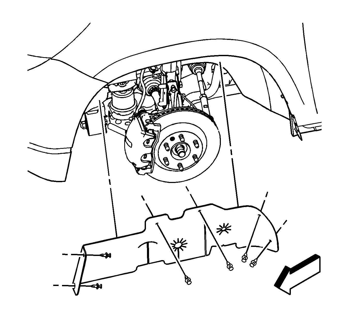
- Remove the left engine splash shield. Refer to Engine Splash Shield Replacement.
- Remove the exhaust flexible pipe. Refer to Exhaust Flexible Pipe Replacement.
- Remove the propeller shaft if the vehicle is equipped with all wheel drive. Refer to Propeller Shaft Replacement.
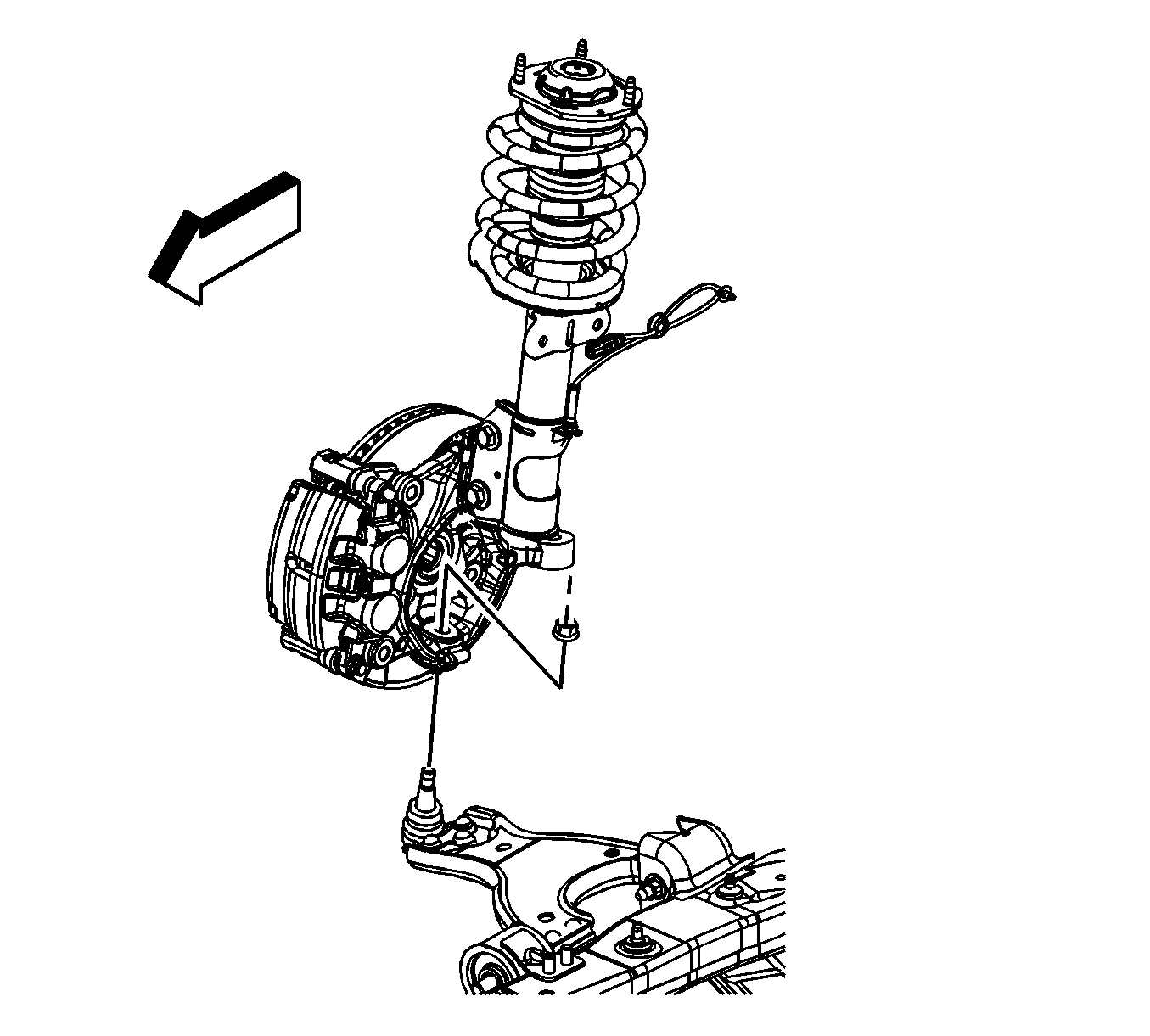
- Remove both lower ball joint retaining nuts. Refer to Lower Control Arm Replacement.
- Remove the lower ball joints from the steering knuckles. Refer to Lower Control Arm Replacement.
- Disconnect the stabilizer shaft links from the stabilizer shaft. Refer to Stabilizer Shaft Link Replacement.
- Remove the power steering gear heat shields. Refer to Steering Gear Heat Shield Replacement.
- Disconnect the intermediate shaft from the steering gear stub shaft. Refer to Intermediate Steering Shaft Replacement.
- Remove the power steering gear bolts. Refer to Steering Gear Replacement.
- Remove the power steering gear from the frame. Refer to Steering Gear Replacement.
- Use mechanics wire secure the power steering gear to the exhaust manifold.
- Remove the power steering cooler inlet pipe from the frame. Refer to Power Steering Cooler Pipe/Hose Replacement.
- Remove and discard the engine and transmission mount lower nuts.
- Lower the vehicle until the frame contacts the J 39580 .
- Remove the underbody rear side rail. Refer to Underbody Rear Side Rail Replacement.
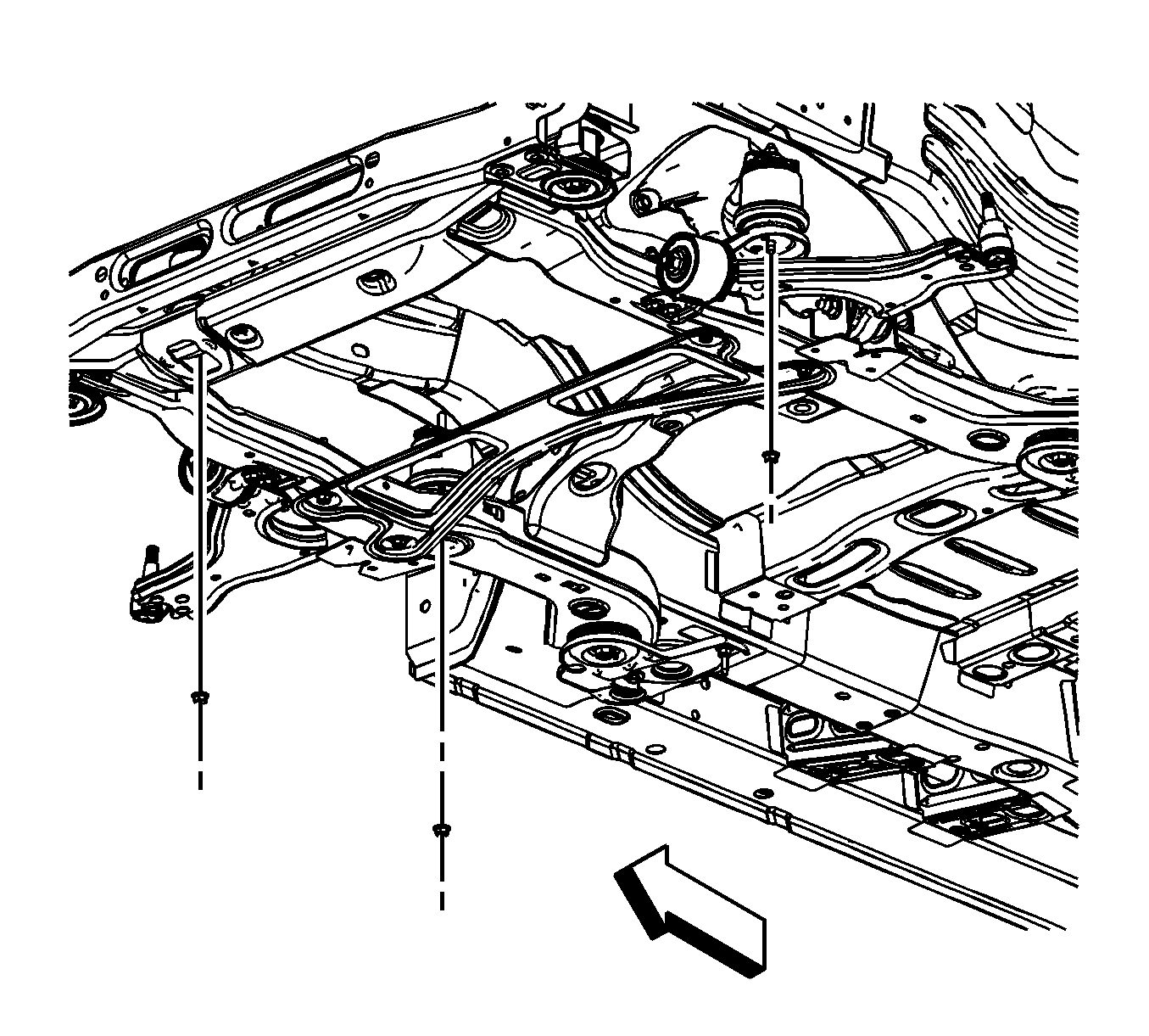
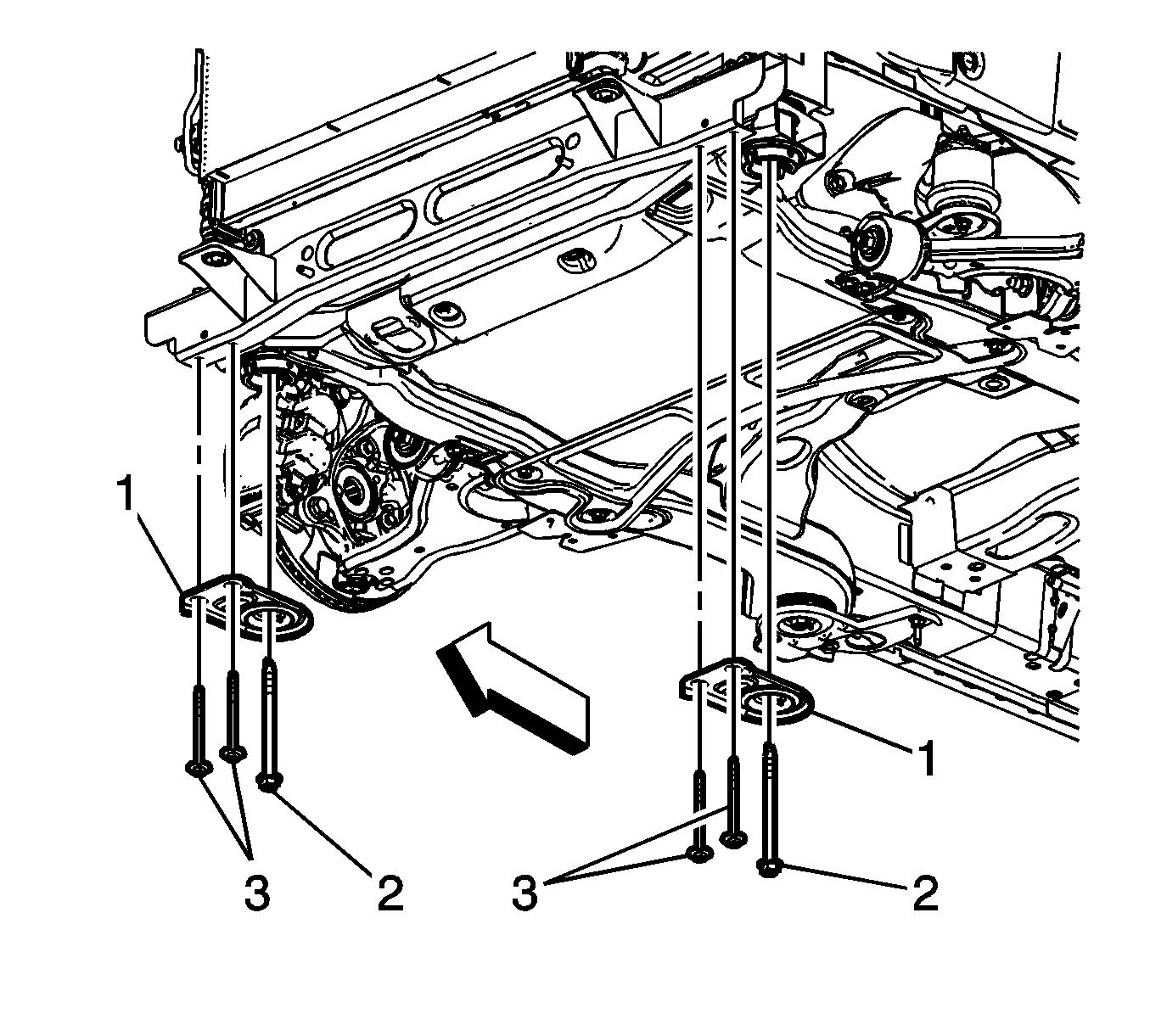
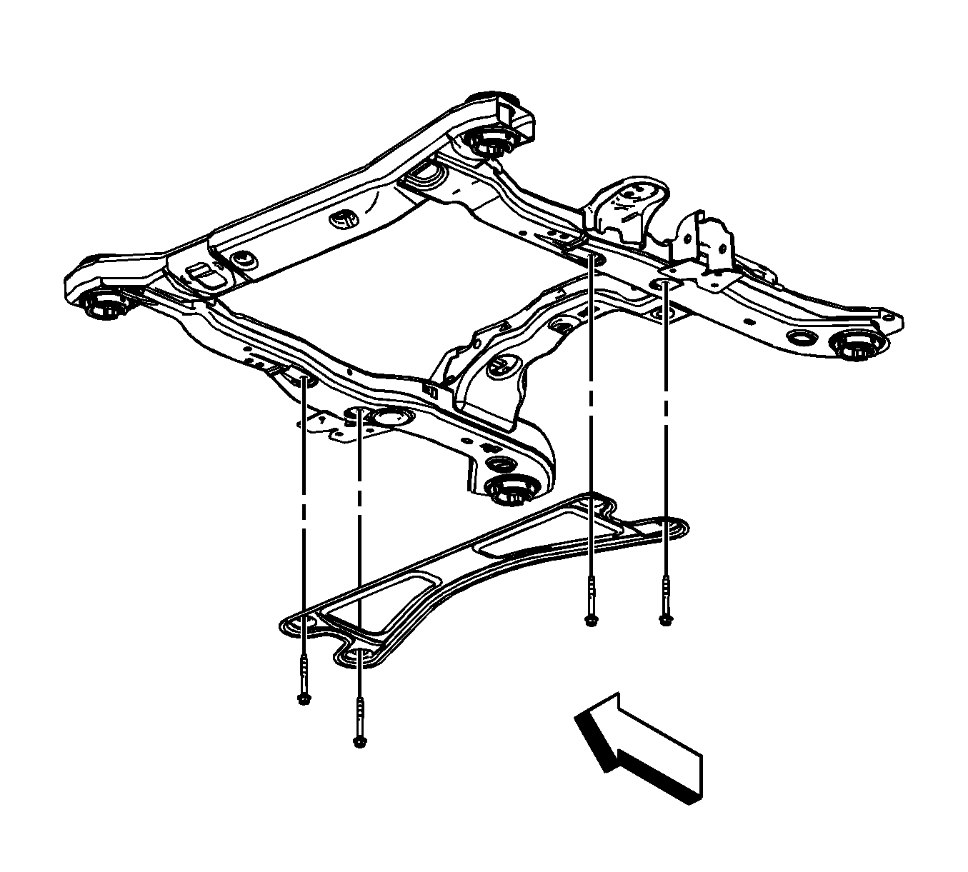
- Remove the front crossmember brace bolts (3).
- Remove the front frame to body bolts (2).
- Remove the front crossmember brace (1).
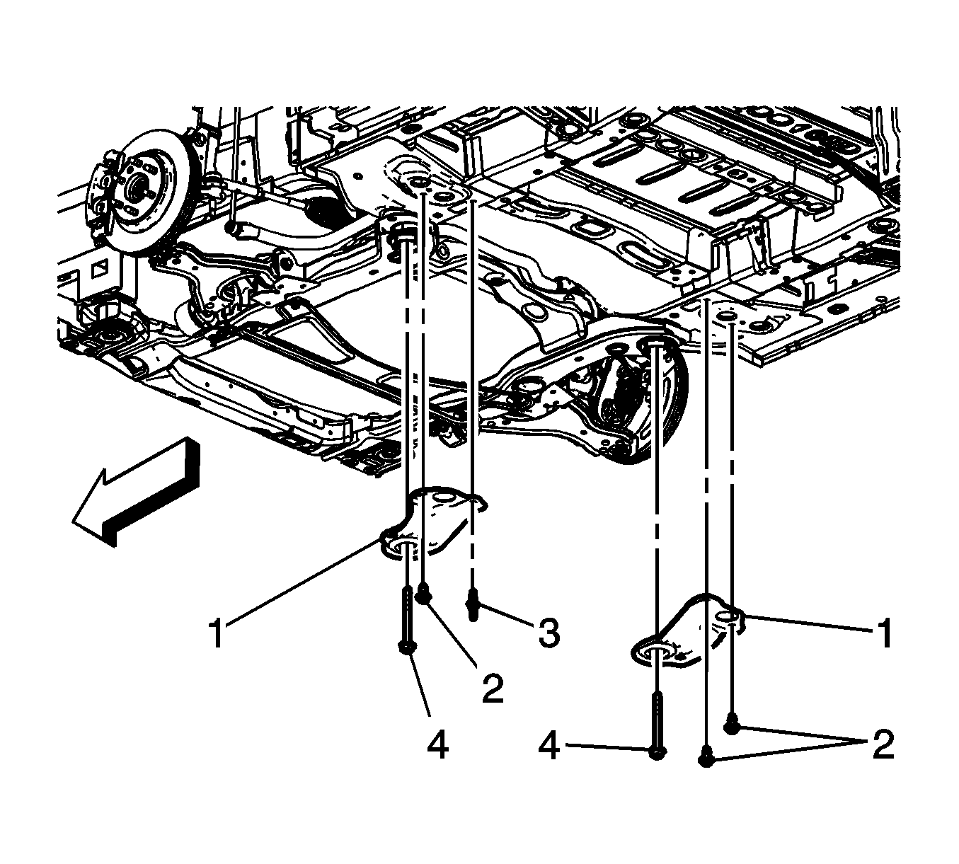
- Remove the reinforcement bolts (2).
- Remove the reinforcement studs (3).
- Remove the frame to body bolts (4).
- Remove the reinforcements (1).
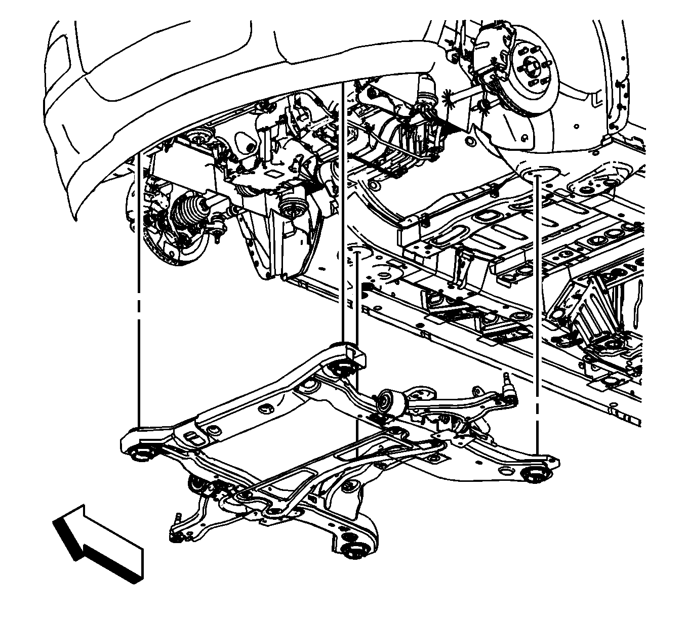
- Raise the vehicle in order to separate the frame from the vehicle.
- Remove the frame brace bolts.
- Remove the frame brace.
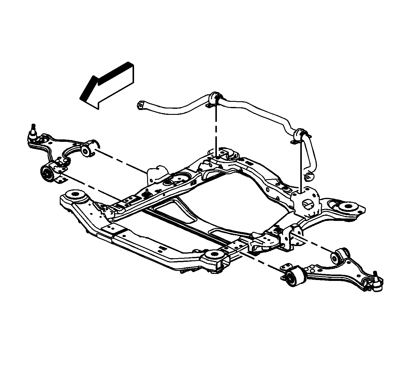
- Remove the stabilizer shaft. Refer to Stabilizer Shaft Insulator Replacement.
- Remove the lower control arms. Refer to Lower Control Arm Replacement.
- Remove the frame insulators from the frame. Refer to Front Frame Cushion or Insulator Replacement and Rear Frame Cushion or Insulator Replacement.
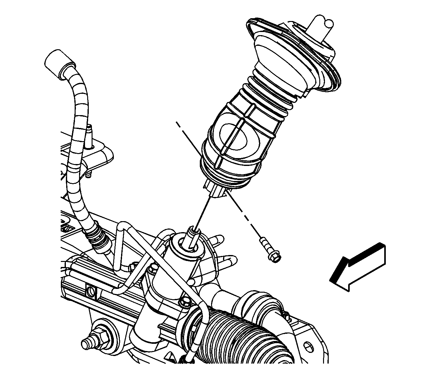
Note: Whenever the steering gear is moved in relation to the body, disconnect the intermediate shaft from the steering gear stub shaft.
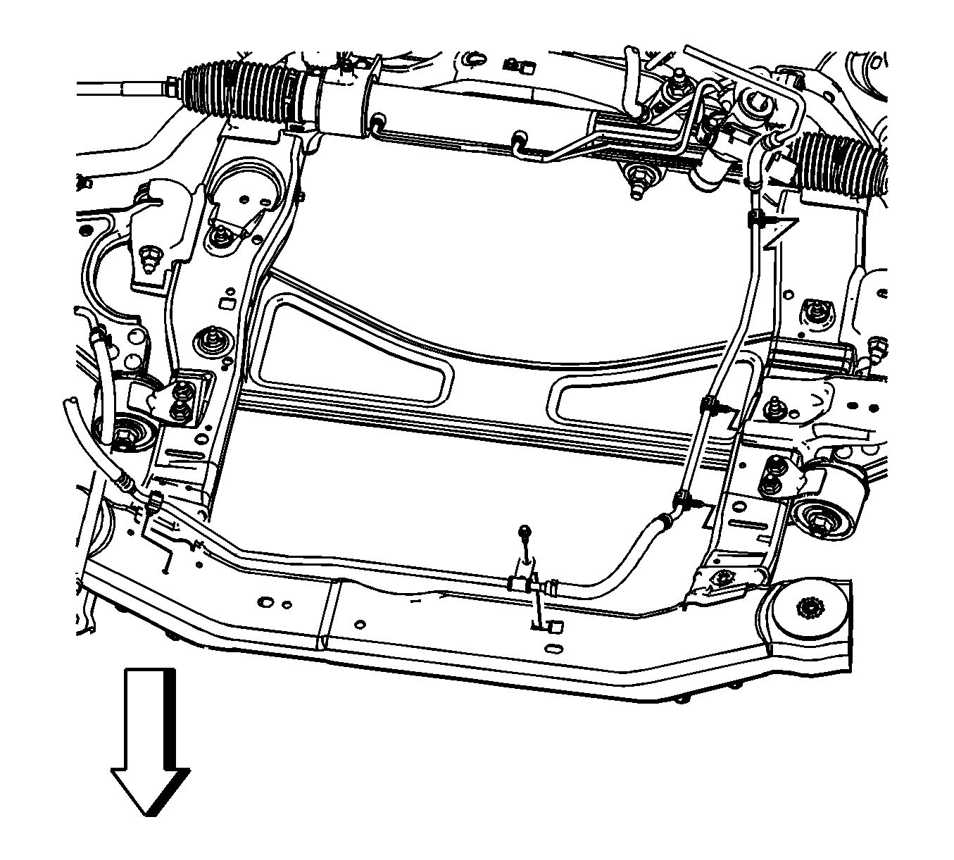
Note: When the frame insulator bolts are removed, always discard the bolts and replace with new bolts.
Installation Procedure
- Install the frame insulators to the frame. Refer to Front Frame Cushion or Insulator Replacement and Rear Frame Cushion or Insulator Replacement.
- Install the lower control arms. Refer to Lower Control Arm Replacement.
- Install the stabilizer shaft. Refer to Stabilizer Shaft Insulator Replacement.
- Install the frame brace.
- Install the frame brace bolts and tighten to 60 N·m (44 lb ft)
- Position the transmission table with the frame under the vehicle.
- Lower the vehicle while aligning the powertrain mounts with the frame until the vehicle is close to the frame.
- Inserting two 19 mm (0.75 in) diameter X 203 mm (8.0 in) long guide pins or drill bits into the frame rear alignment holes in order to align the frame.
- Install the front crossmember brace (1).
- Install the front frame to body bolts (2) and tighten to 110 N·m (81 lb ft) plus 90 degrees.
- Install the front crossmember brace bolts (3) and tighten to 50 N·m (37 lb ft).
- Install the reinforcements (1).
- Install the rear frame to body bolts (4) and tighten to 110 N·m (81 lb ft) plus 90 degrees.
- Install the reinforcement bolts (2) and tighten to 60 N·m (44 lb ft).
- Install the reinforcement studs (3) and tighten to 60 N·m (44 lb ft).
- Remove the alignment pins from the frame.
- Install the underbody rear side rail. Refer to Underbody Rear Side Rail Replacement.
- Apply threadlocker GM P/N 12345382 (Canadian P/N 10953489) to the engine and transmission mount threads.
- Install the engine and transmission mount nuts and tighen to 75 N·m (55 lb ft).
- Install the power steering cooler inlet pipe to the frame. Refer to Power Steering Cooler Pipe/Hose Replacement.
- Install the power steering gear to the frame. Refer to Steering Gear Replacement.
- Install the power steering gear bolts. Refer to Steering Gear Replacement.
- Install the power steering gear heat shield. Refer to Steering Gear Heat Shield Replacement.
- Disconnect the intermediate shaft from the steering gear stub shaft. Refer to Intermediate Steering Shaft Replacement.
- Connect the stabilizer shaft links to the stabilizer shaft. Refer to Stabilizer Shaft Link Replacement.
- Install the lower ball joints to the steering knuckles. Refer to Lower Control Arm Replacement.
- Install both lower ball joint retaining nuts. Refer to Lower Control Arm Replacement.
- Install the propeller shaft if the vehicle is equipped with all wheel drive. Refer to Propeller Shaft Replacement.
- Install the exhaust flexible pipe. Refer to Exhaust Flexible Pipe Replacement.
- Install the left engine splash shield. Refer to Engine Splash Shield Replacement.
- Install the front tires and wheels. Refer to Tire and Wheel Removal and Installation.
- Lower the vehicle.
- Remove the engine support fixture.
- Inspect the front wheel alignment and adjust the toe angle if necessary. Refer to Wheel Alignment Measurement.


Caution: Refer to Fastener Caution in the Preface section.

Note: Ensure that the power steering cooler line does not become trapped by the engine mount during this step.
Note: Ensure that the alignment pins remain installed during the frame installation.

Note: If the frame insulator bolt does not screw in smoothly, run a tap through the frame nut in the body in order to remove foreign material. Ensure the tap does not punch through the underbody.
Do not over tighten the insulator. Over tightening may collapse a spacer or strip a bolt.
Note: The engine and transmission mount nuts must be replaced once removed. When the nut has to be loosened or removed, threadlocker must be used in addition to using a new nut. Allow adhesive on new engine and transmission mount nuts to cure for 24 hours after replacement.


Note: Whenever the steering gear is moved in relation to the body, disconnect the intermediate shaft from the steering gear stub shaft.


