For 1990-2009 cars only
Special Tools
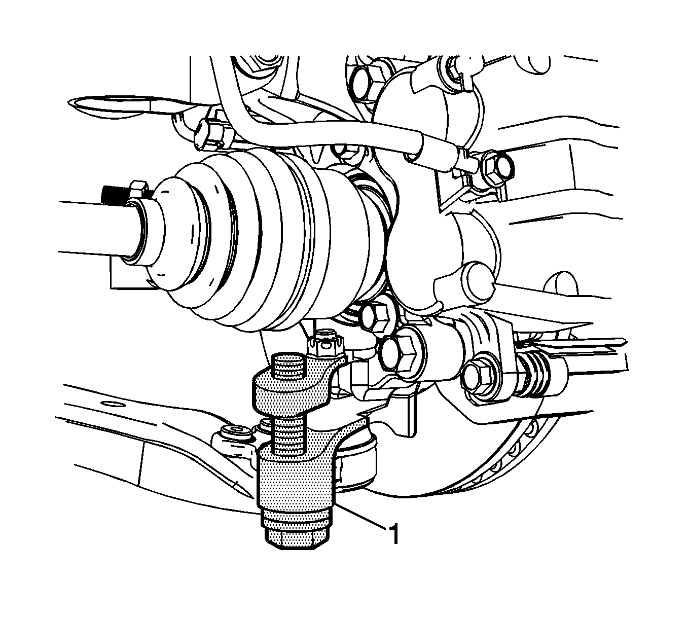
J 42188 Ball Joint Separator
Removal Procedure
- Raise and support the vehicle. Refer to Lifting and Jacking the Vehicle.
- Remove the tire and wheel assembly. Refer to Tire and Wheel Removal and Installation.
- Remove the outer tie rod end from the steering knuckle. Refer to Steering Linkage Outer Tie Rod Replacement.
- Turn the knuckle assembly to left.
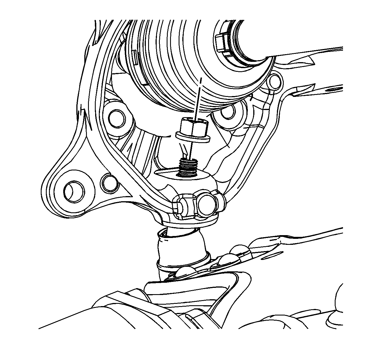
- Using a allen wrench and the proper size wrench, remove the lower ball joint retaining nut.
- Using the J 42188 (1) remove the lower ball joint from the control arm.
- Remove the tool from the lower ball joint.
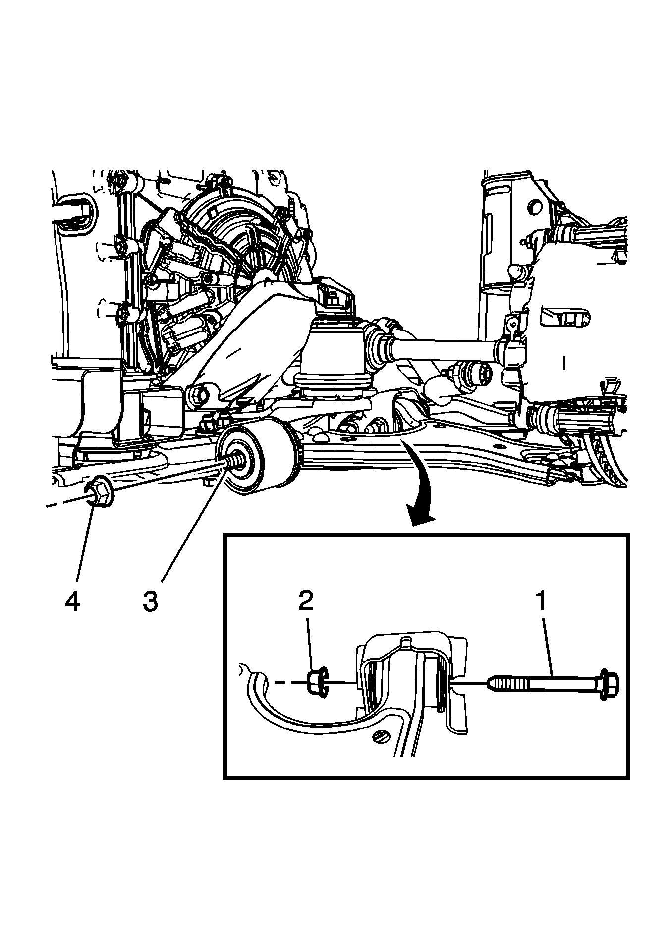
- Remove the front control arm mounting nut (4) from the frame stud (3).
- Remove the rear control arm mounting bolt (1) and nut (2).
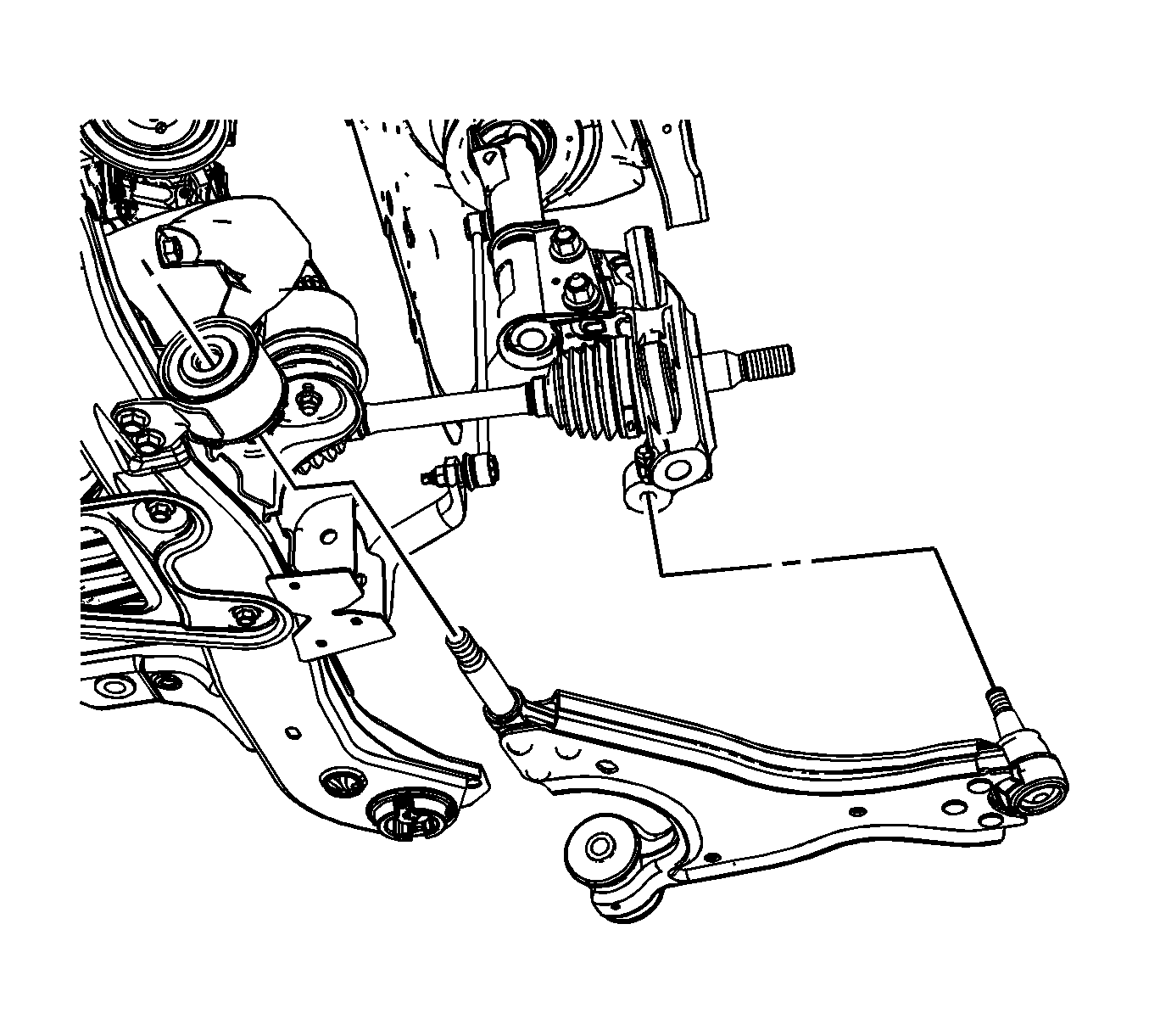
- Remove the lower control arm from the vehicle.


Installation Procedure
- Position the lower control arm in the front bushing and the rear mounting bracket.
- Install and hand tighten the rear lower control arm mounting bolt and nut.
- Install the front lower control arm nut (4) on the mounting stud (3).
- Install the rear lower control arm nut (2) and the bolt (1).
- Install the lower ball joint in the steering knuckle.
- Install the ball joint mounting nut.
- Using an allen wrench with the proper size wrench, tighten the mounting nut.
- Install the outer tie rod end in the steering knuckle. Refer to Steering Linkage Outer Tie Rod Replacement.
- Install the tire and wheel assembly. Refer to Tire and Wheel Removal and Installation.
- Remove the support and lower the vehicle

Notice: Refer to Fastener Notice in the Preface section.

Tighten
Tighten the front lower control arm nut to 150 N·m (111 lb ft).
Tighten
Tighten the rear lower control arm nut to 75 N·m (55 lb ft).

Tighten
Tighten the mounting nut to 40 N·m (30 lb ft) plus 120 degrees.
