GM Service Manual Online
For 1990-2009 cars only
Figure 1:

Module Power, Ground, Serial Data, and MIL
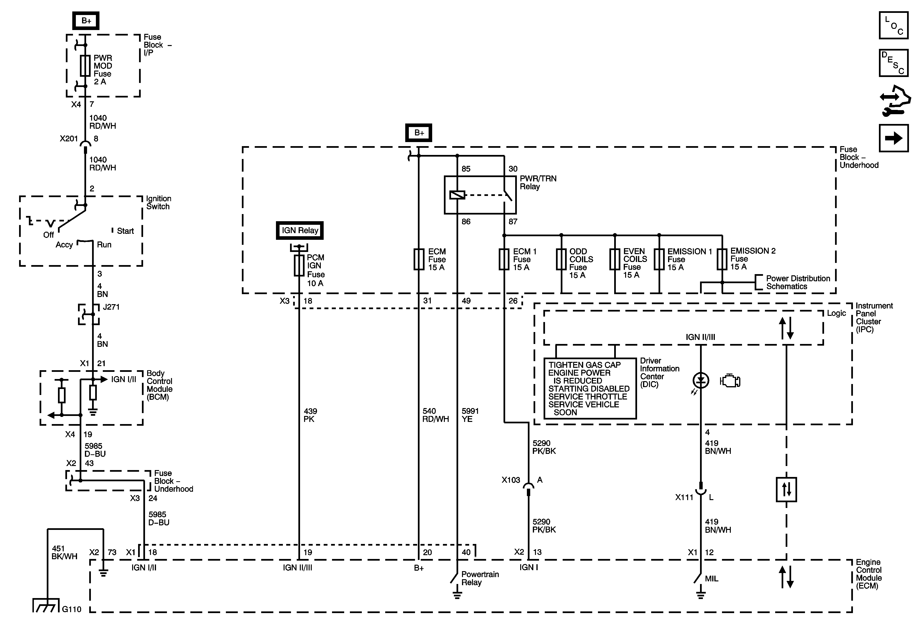

Object Number: 1843885  Size: FS
Master Electrical Component List
Engine Control Module Description
Control Module References
5V1 and Low Reference Bus
AIRBAG, AMP, BATT 1, BCM, CNSTR/VENT, CSTY, DISPLAY, INADV/PWR/LED, INFOTAINMENT, MSM, POWER MOD, and RADIO Fuses
B+ Bus 2 of 2
B+ Bus 2 of 2
EMISSION 1 and EMISSION 2 Fuse
G105 and G110
Data Communication Schematics
Figure 2:

5-Volt Reference 1 and Low Reference Bus
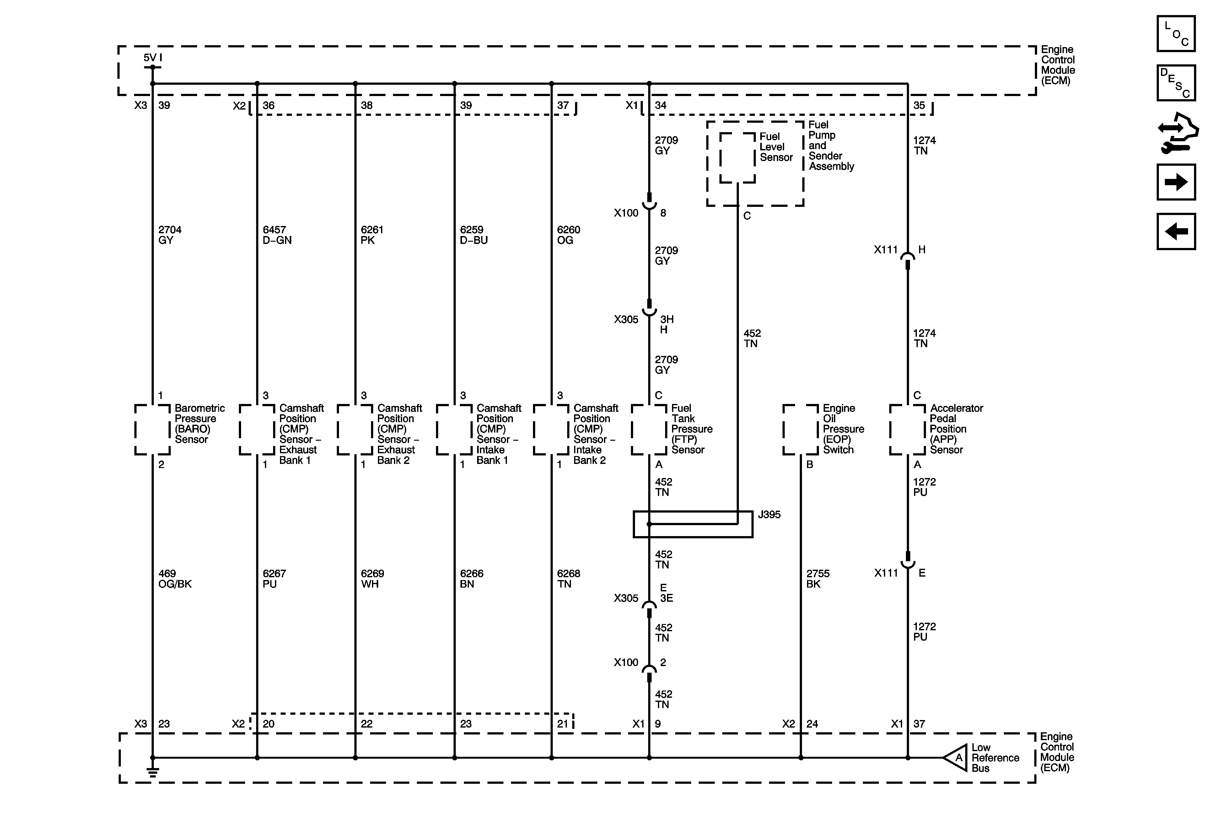

Object Number: 1843886  Size: FS
Master Electrical Component List
Engine Control Module Description
Control Module References
5V2 and Low Reference Bus
Module Power, Ground, Serial Data, and MIL
5V2 and Low Reference Bus
Figure 3:

5-Volt Reference 2 and Low Reference Bus
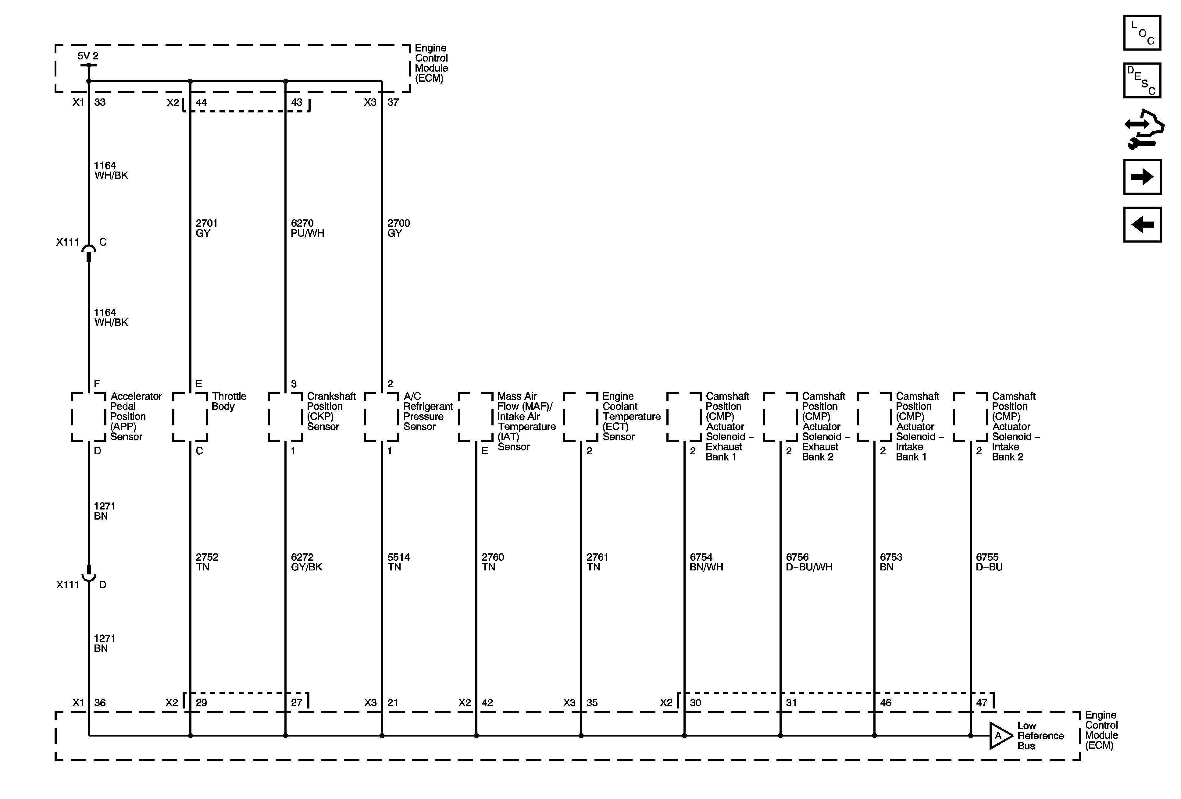

Object Number: 1843887  Size: FS
Master Electrical Component List
Engine Control Module Description
Control Module References
Engine Data Sensors - Pressure, Temperature, and Extended Brake Travel
5V1 and Low Reference Bus
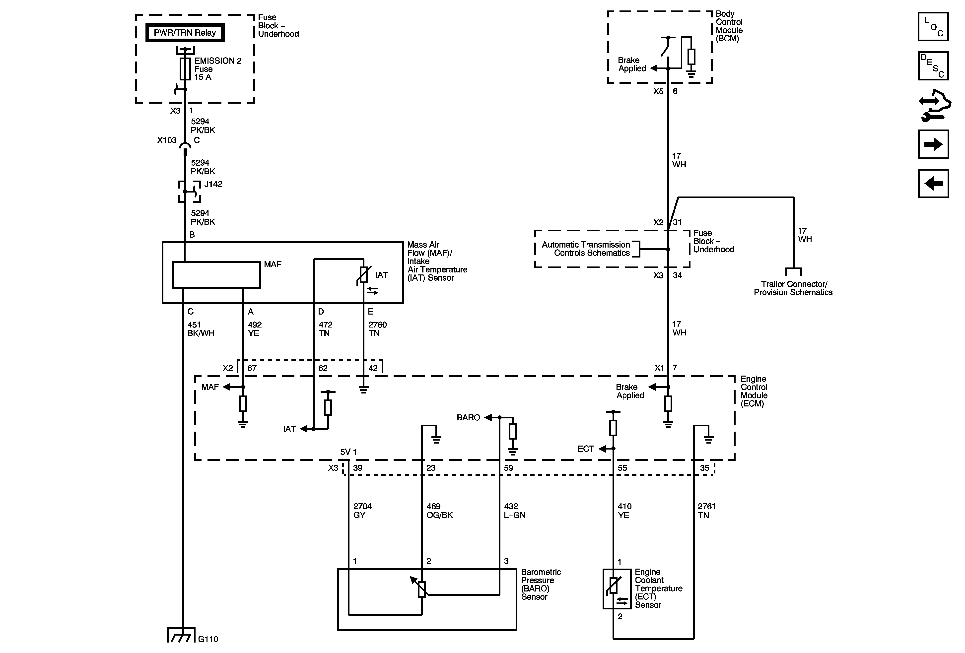
Figure 4:

Engine Data Sensors - Pressure, Temperature, and Extended Brake Travel


Object Number: 1843888  Size: FS
Master Electrical Component List
Engine Control Module Description
Control Module References
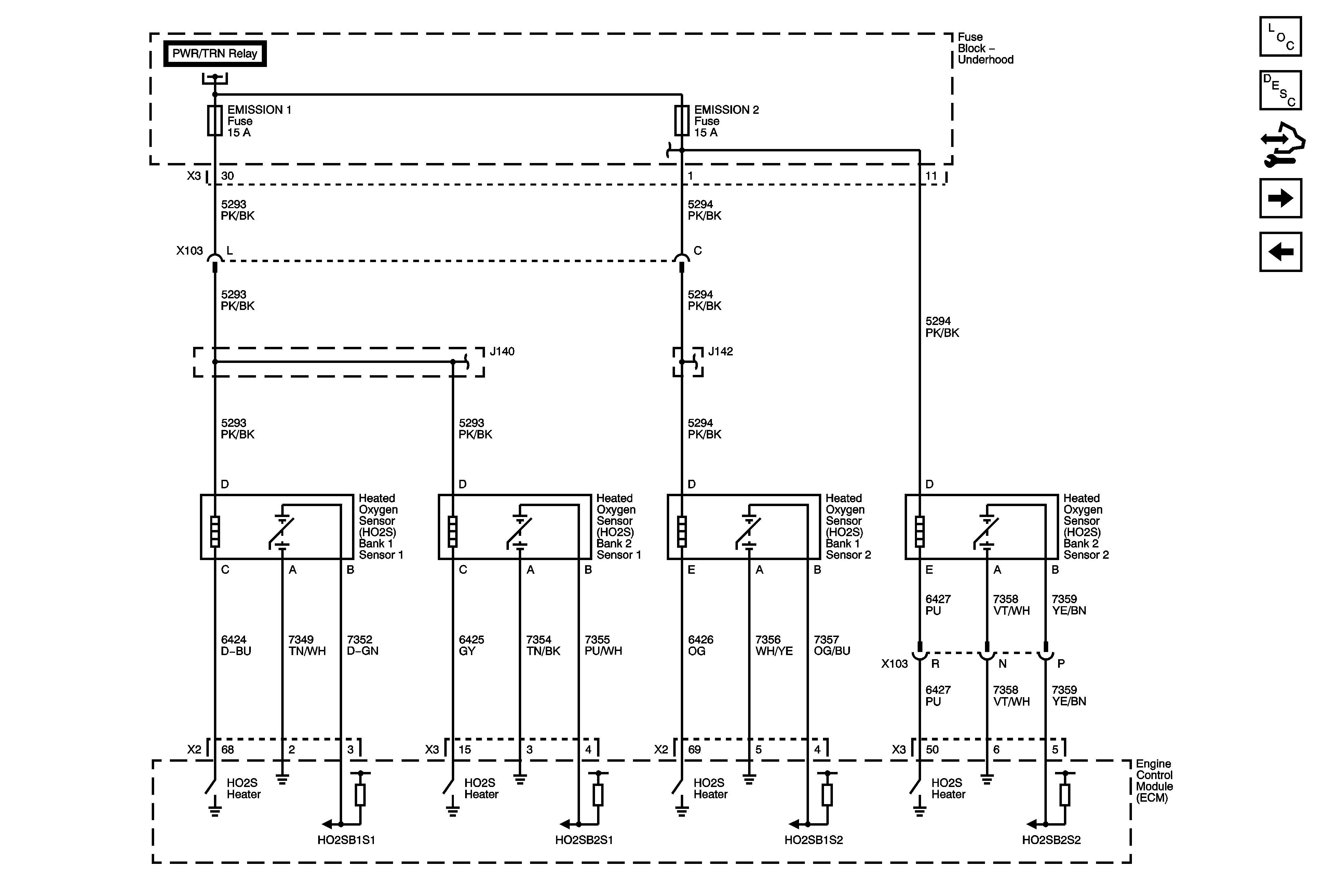
Engine Data Sensors - Oxygen Sensors
5V2 and Low Reference Bus
B+ Bus 2 of 2
Module Power, Ground, Data Communication, MIL and Brake Applied Signal
Blunt Cuts - V92
G105 and G110
Figure 5:

Engine Data Sensors - Oxygen Sensors


Object Number: 1843889  Size: FS
Master Electrical Component List
Engine Control Module Description
Control Module References
Engine Data Sensors - Throttle Actuator Controls
Engine Data Sensors - Pressure, Temperature, and Extended Brake Travel
B+ Bus 2 of 2
B+ Bus 2 of 2
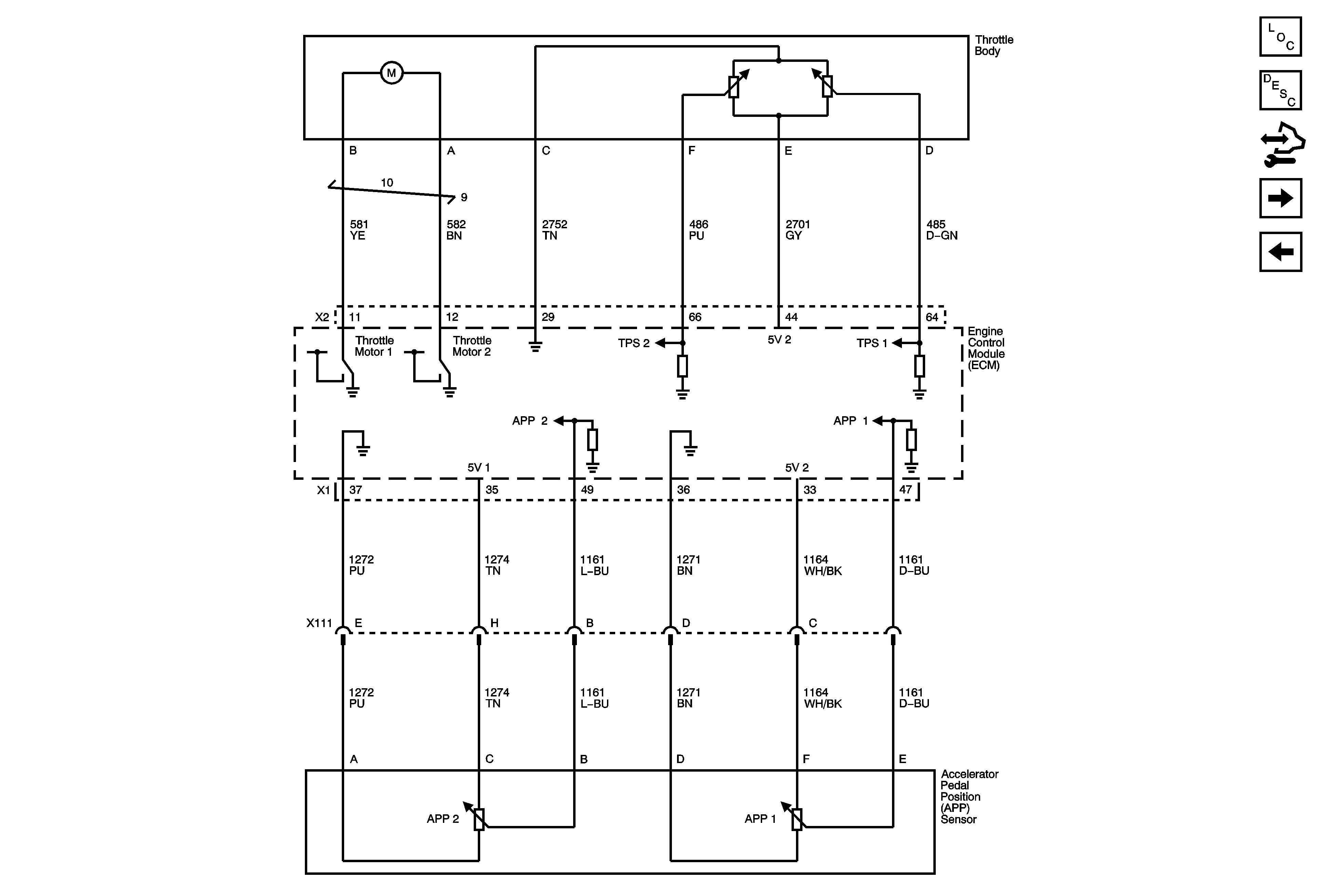
Figure 6:

Engine Data Sensors - Throttle Actuator Controls


Object Number: 1843890  Size: FS
Master Electrical Component List
Engine Control Module Description
Control Module References
Ignition Controls - Bank 1 Ignition System
Engine Data Sensors - Oxygen Sensors
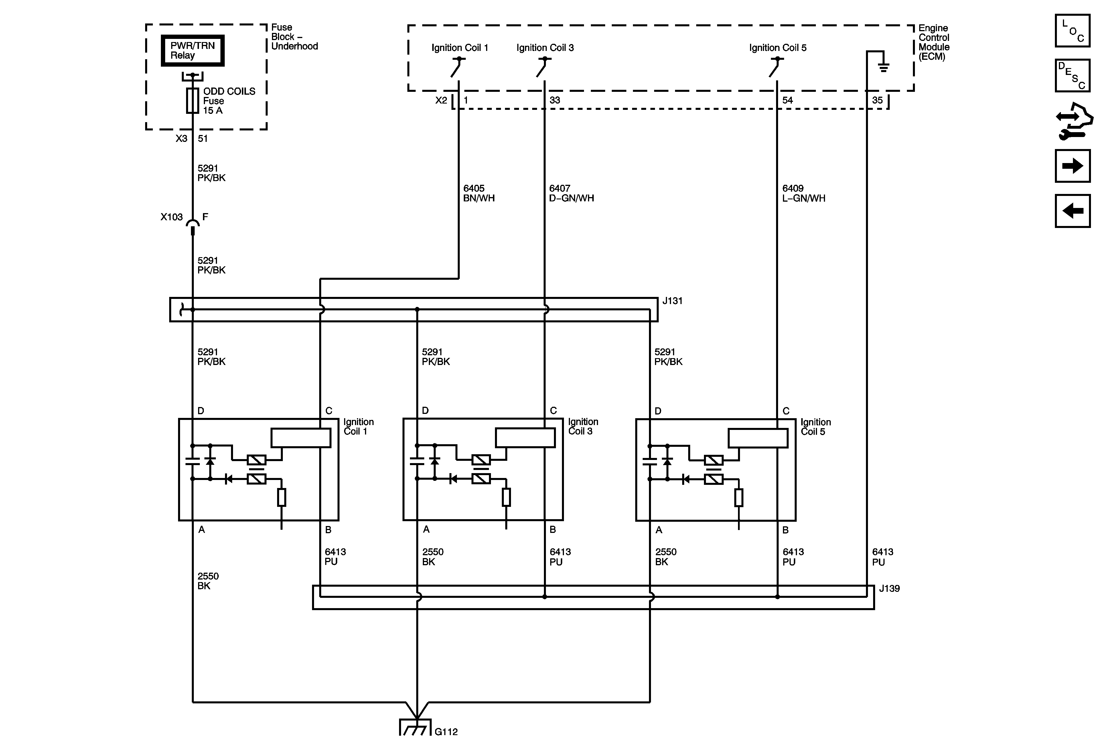
Figure 7:

Ignition Controls - Bank 1 Ignition System


Object Number: 1843891  Size: FS
Master Electrical Component List
Engine Control Module Description
Control Module References
Ignition Controls - Bank 2 Ignition System
Engine Data Sensors - Throttle Actuator Controls
B+ Bus 2 of 2
G112, G114, and G115
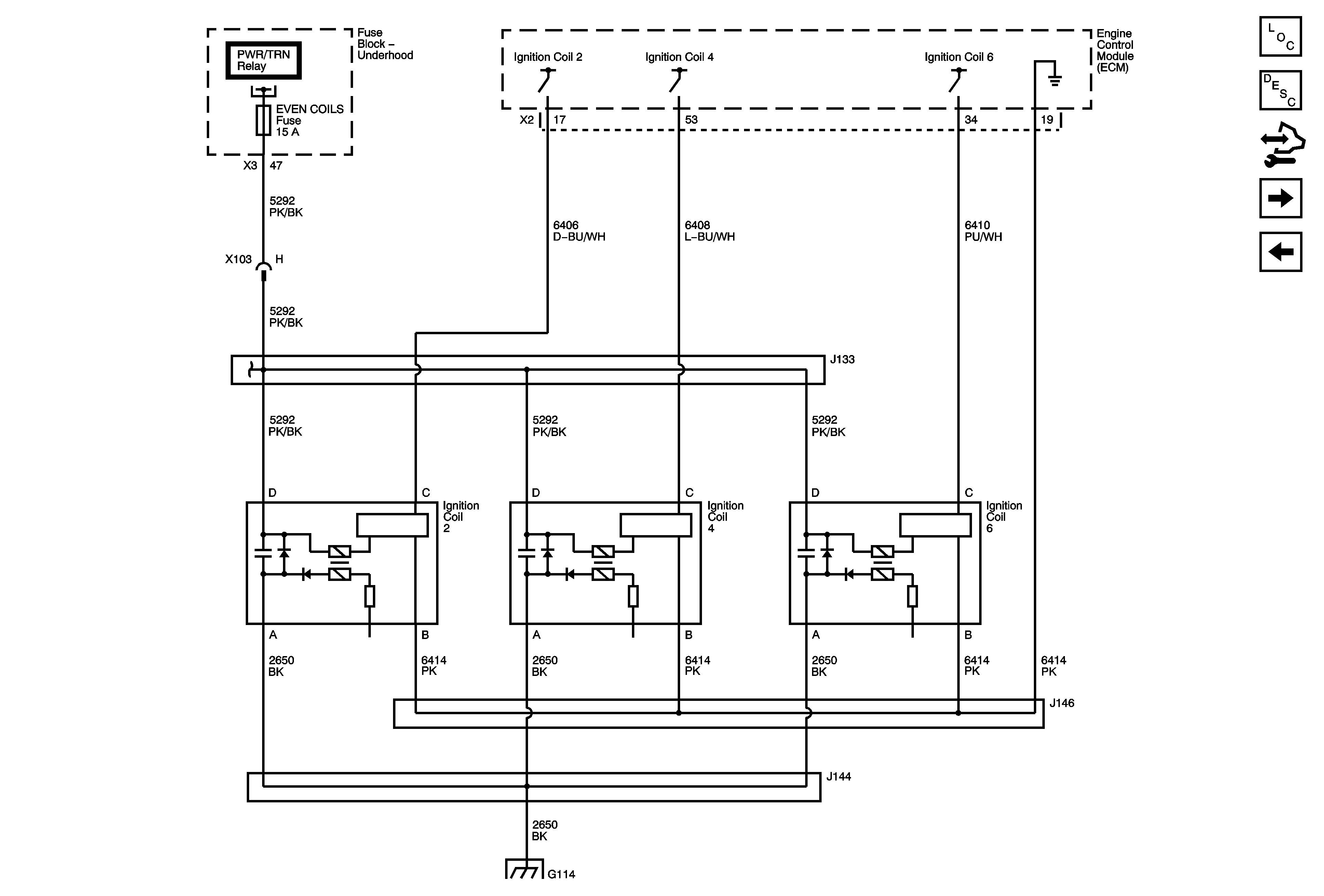
Figure 8:

Ignition Controls - Bank 2 Ignition System


Object Number: 1843892  Size: FS
Master Electrical Component List
Engine Control Module Description
Control Module References
Ignition Controls - CKP and KS Sensors
Ignition Controls - Bank 1 Ignition System
B+ Bus 2 of 2
G112, G114, and G115
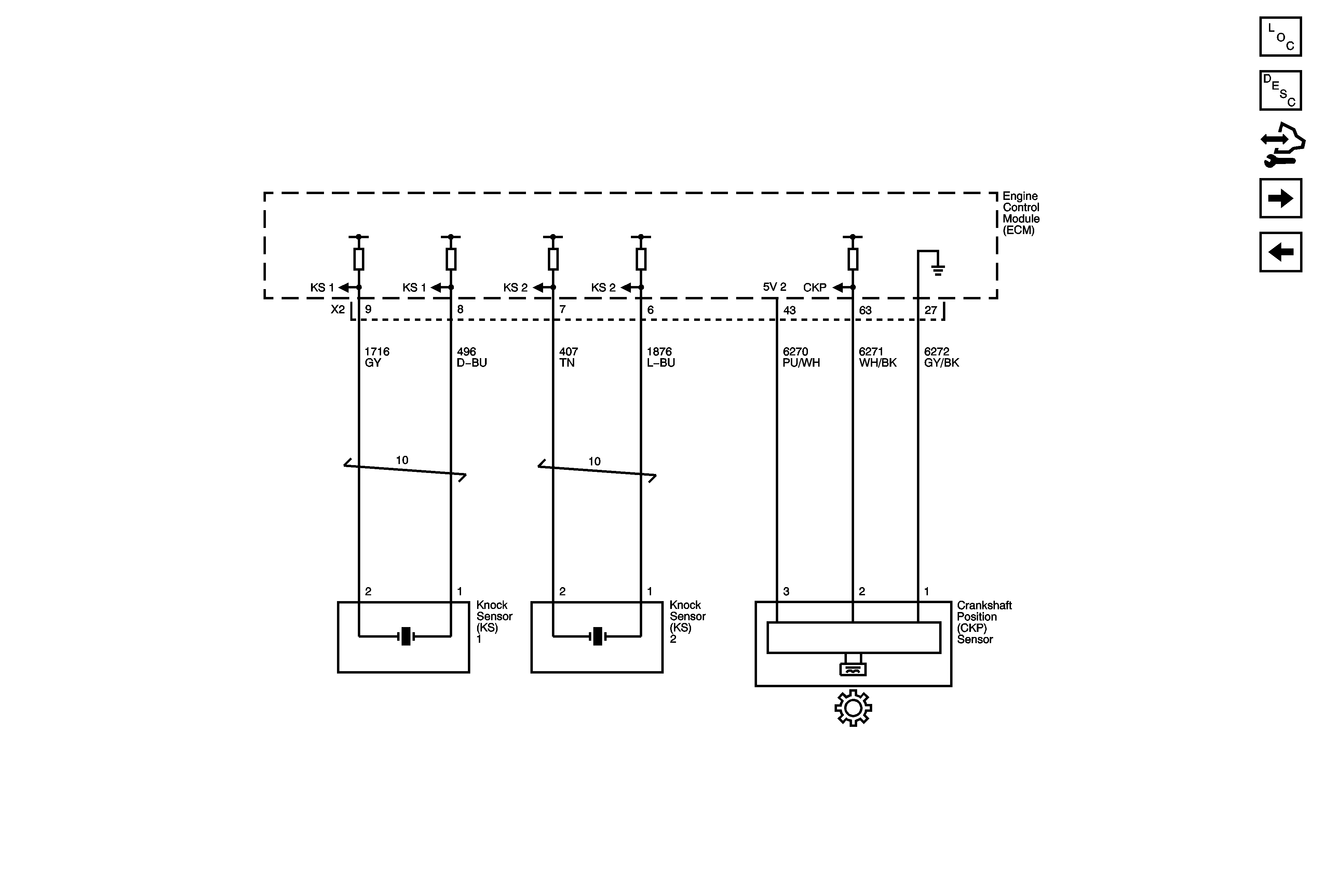
Figure 9:

Ignition Controls - CKP and KS Sensors


Object Number: 1843893  Size: FS
Master Electrical Component List
Engine Control Module Description
Control Module References
Ignition Controls - CMP Sensors and Actuator Solenoids
Ignition Controls - Bank 2 Ignition System
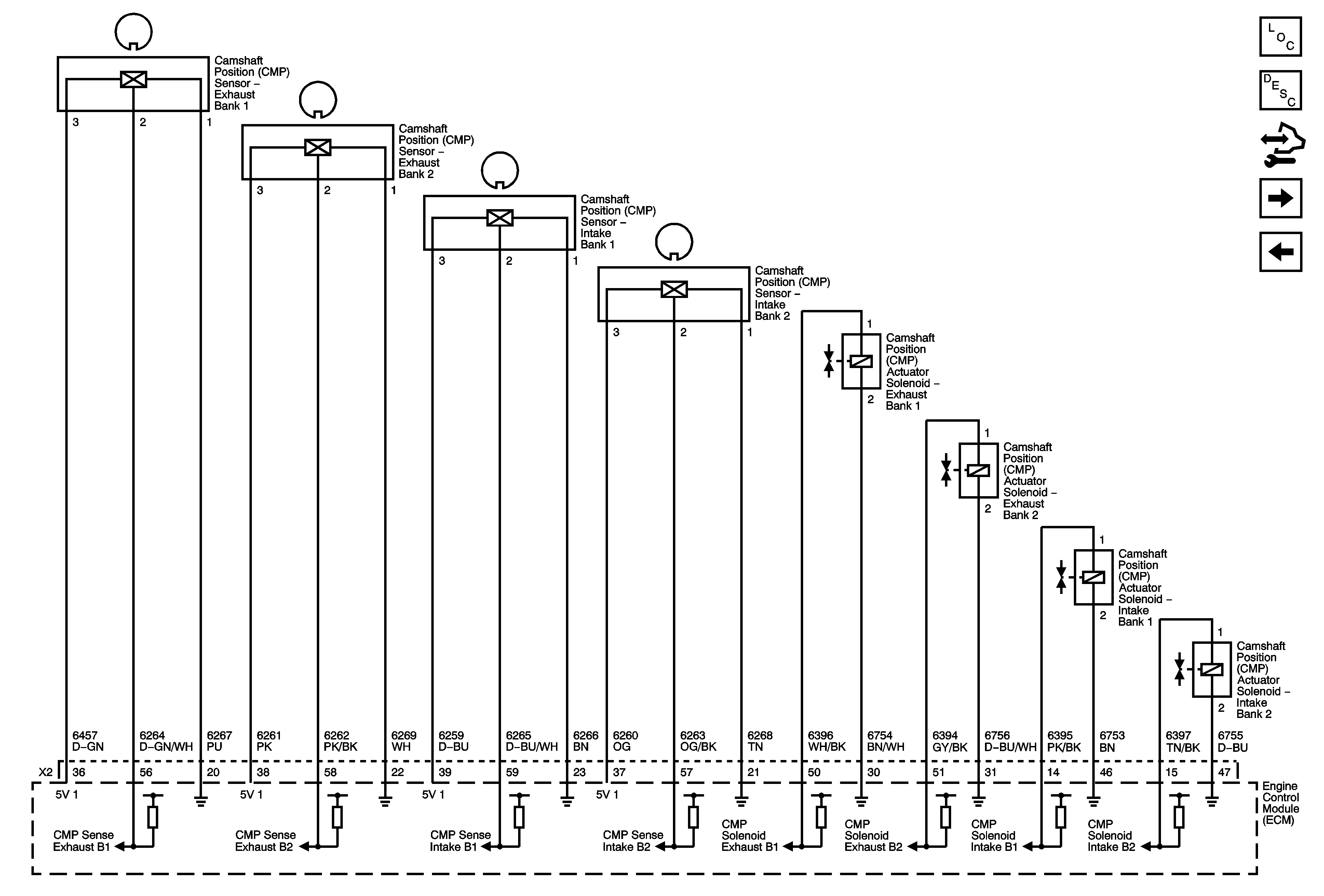
Figure 10:

Ignition Controls - CMP Sensors and Actuator Solenoids


Object Number: 1843894  Size: FS
Master Electrical Component List
Camshaft Actuator System Description
Control Module References
Fuel Controls - Fuel Pump and Fuel Injectors
Ignition Controls - CKP and KS Sensors
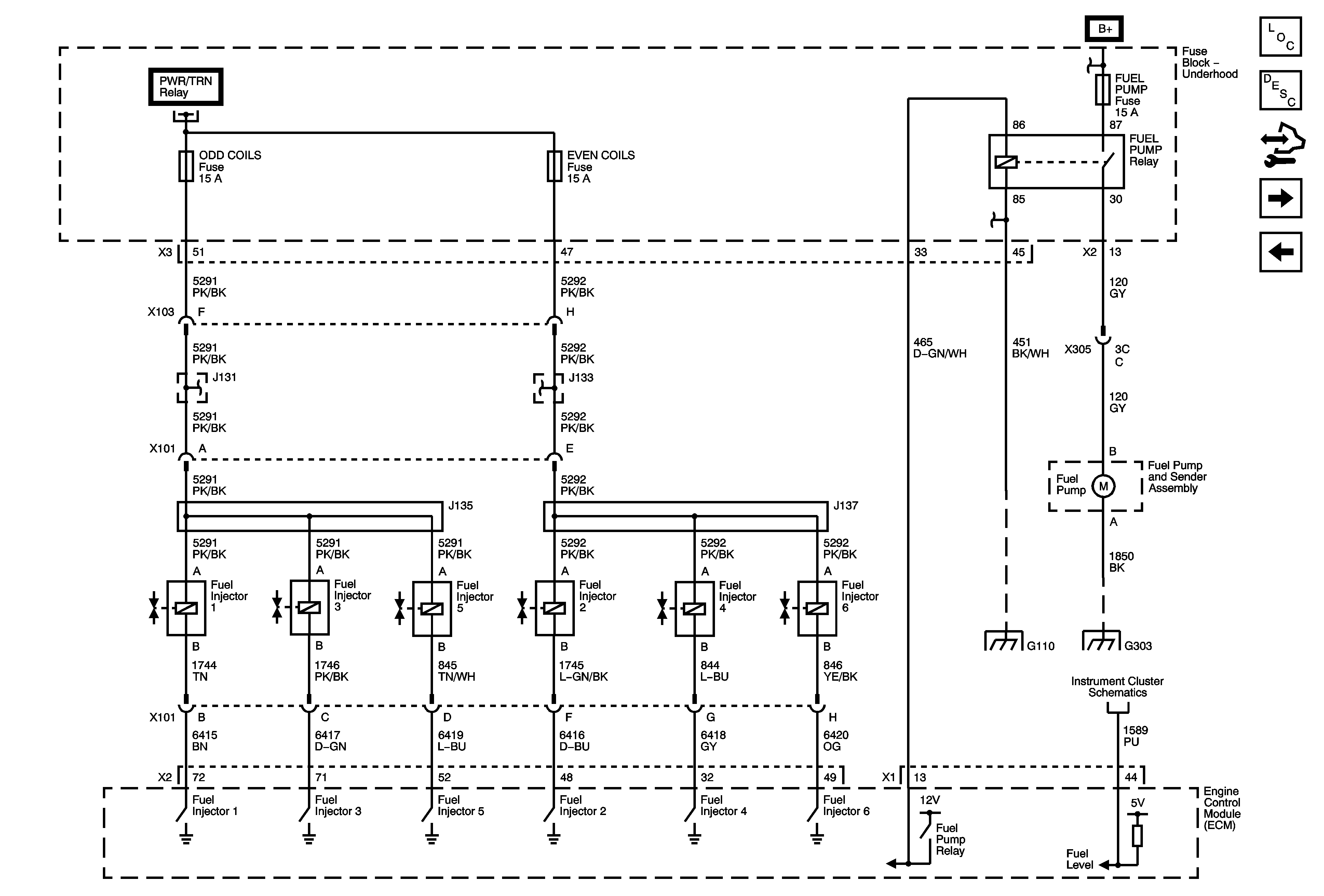
Figure 11:

Fuel Controls - Fuel Pump and Fuel Injectors


Object Number: 1843895  Size: FS
Master Electrical Component List
Fuel System Description
Control Module References
Fuel Controls - EVAP Controls and Manifold Tuning
Ignition Controls - CMP Sensors and Actuator Solenoids
B+ Bus 2 of 2
B+ Bus 2 of 2
B+ Bus 1 of 2
G105 and G110
Gages, Ground, and Power
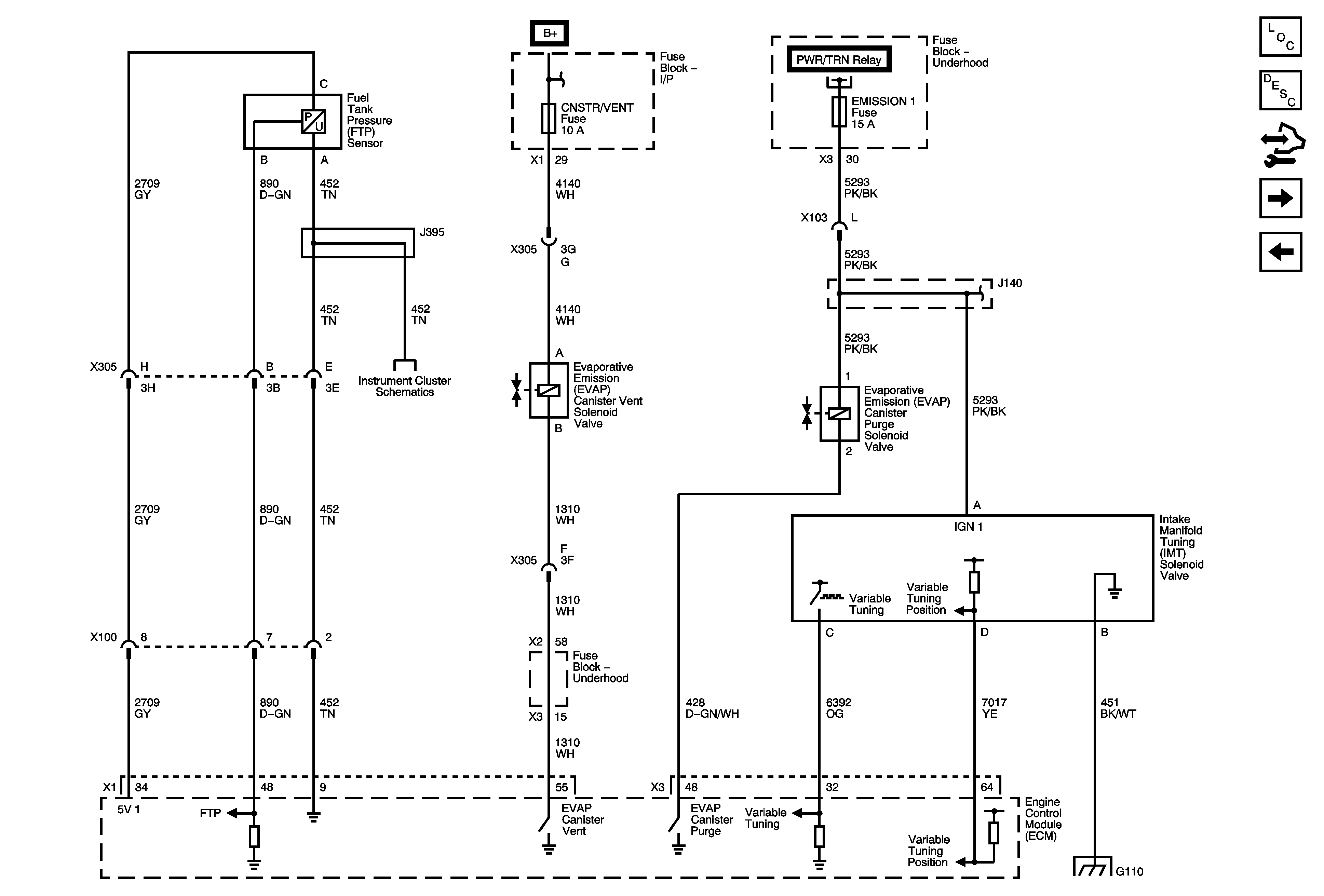
Figure 12:

Fuel Controls - EVAP Controls and Manifold Tuning


Object Number: 1843896  Size: FS
Master Electrical Component List
Evaporative Emission Control System Description
Control Module References
Subsystem References
Fuel Controls - Fuel Pump and Fuel Injectors
AIRBAG, AMP, BATT 1, BCM, CNSTR/VENT, CSTY, DISPLAY, INADV/PWR/LED, INFOTAINMENT, MSM, POWER MOD, and RADIO Fuses
B+ Bus 2 of 2
Gages, Ground, and Power
G105 and G110
Figure 13:

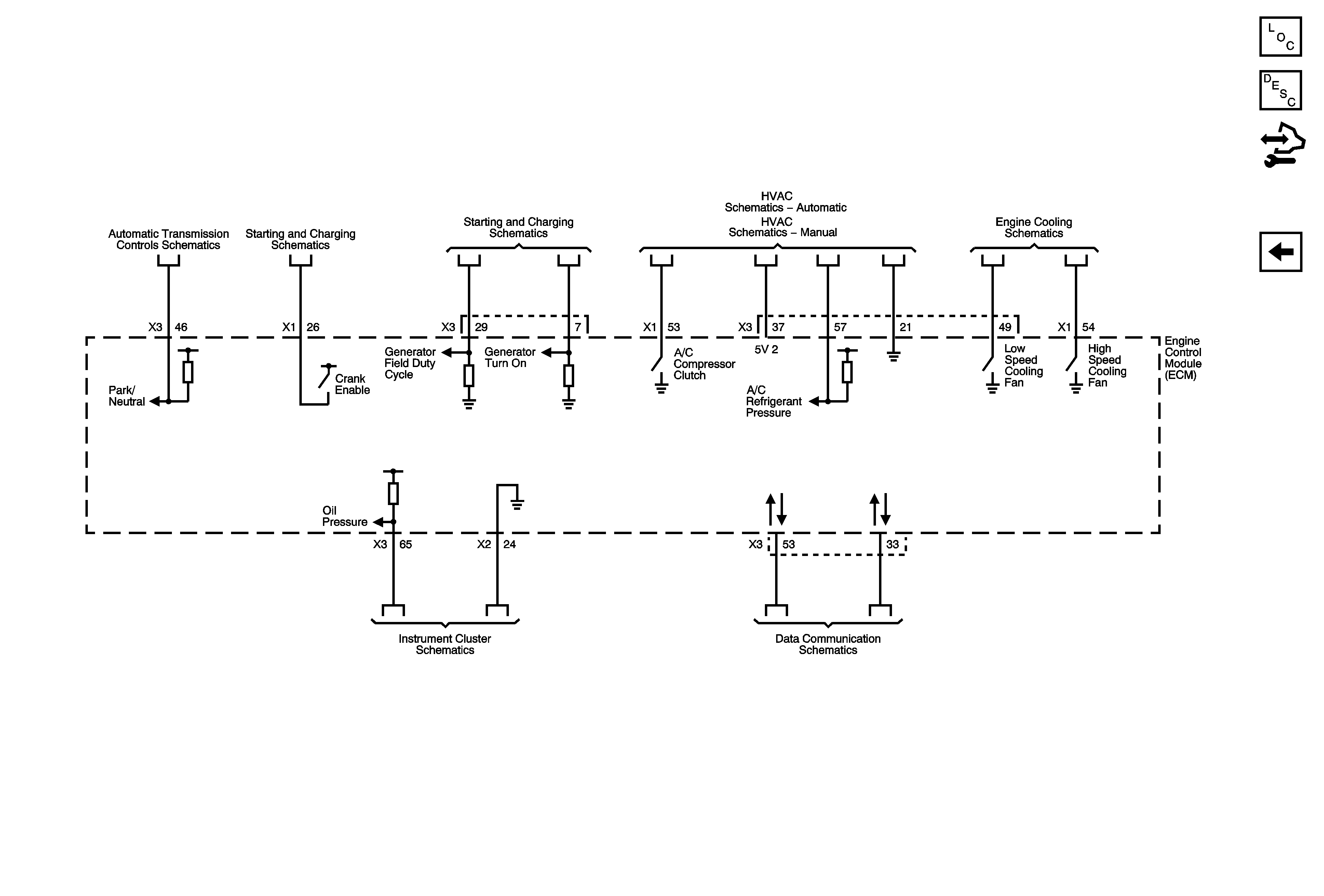
Subsystem References


Object Number: 1843897  Size: FS
Master Electrical Component List
Engine Control Module Description
Control Module References
Fuel Controls - Fuel Pump and Fuel Injectors
IMS and Tap Up/Tap Down
Starting
Charging
Compressor Controls
Compressor Controls
Engine Cooling
Indicators and Lighting
Data Communication Schematics