| Table 1: | Fluid Seal Ring Installation |
| Table 2: | 2-6 Clutch Piston Installation |
| Table 3: | Low and Reverse Clutch Piston Installation |
| Table 4: | 2-6 and Low-Reverse Piston Function Inspection |
| Table 5: | Input Speed Sensor Installation |
Fluid Seal Ring Installation
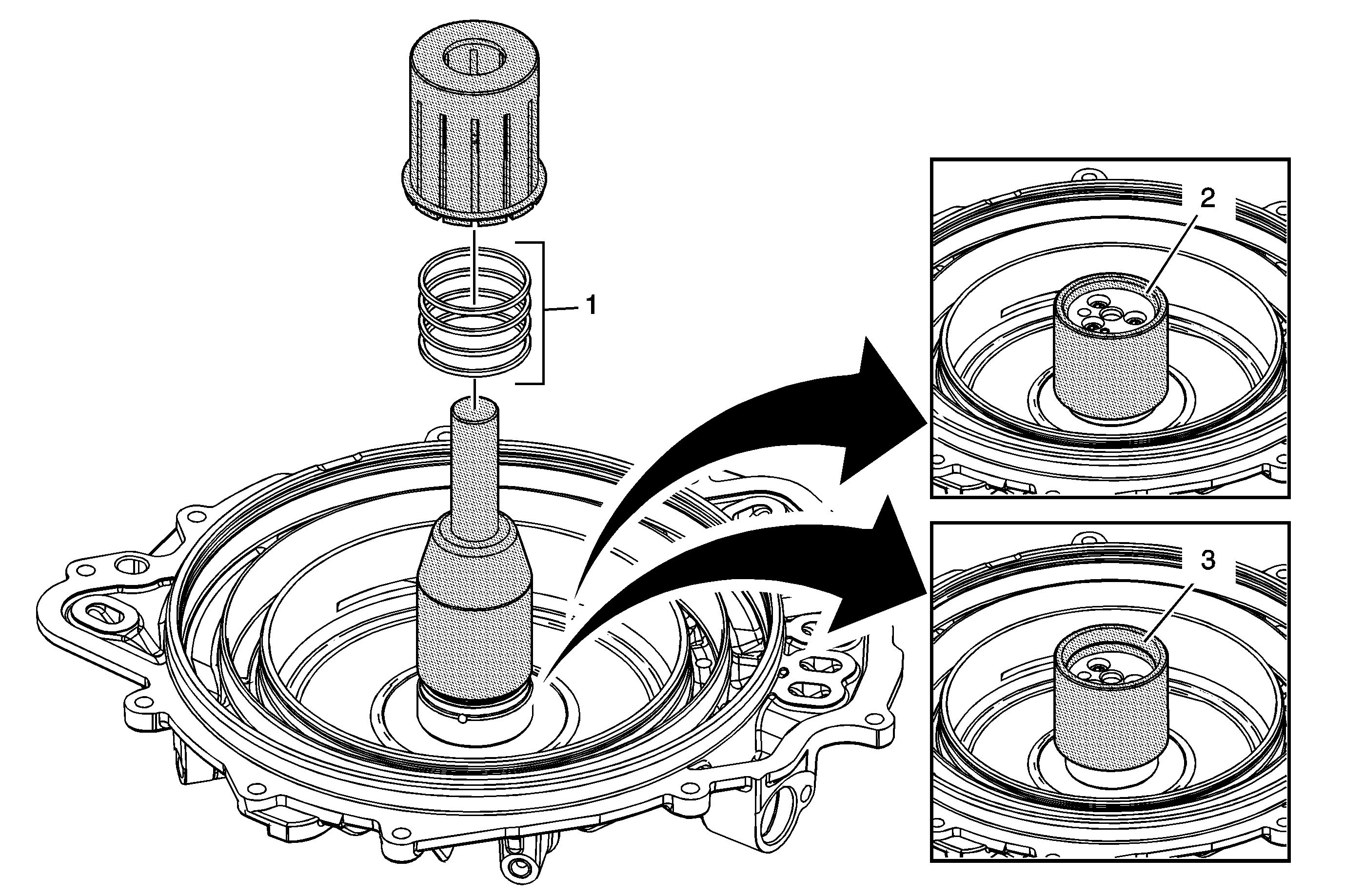
Callout | Component Name |
|---|---|
1 | 3-5 Reverse and 4-5-6 Clutch Fluid Seal Ring Procedure
Special ToolJ-46620 Seal Installer |
2 | Small Chamfer Up Notice: Do not force J 46620-1 down over the seals as this will roll and damage the seals. The large chamfer is designed to fit over the over stretched seal. Use a hand to help shrink the seal if J 46620-1 is difficult to install over the seal rings. ProcedureInstall J 46620-1 which is part of J-46620 with the large chamfer end down over the fluid seal rings and leave J 46620-1 which is part of J-46620 on the seals for at least 60 seconds. |
3 | Large Chamfer Up Procedure
|
2-6 Clutch Piston Installation
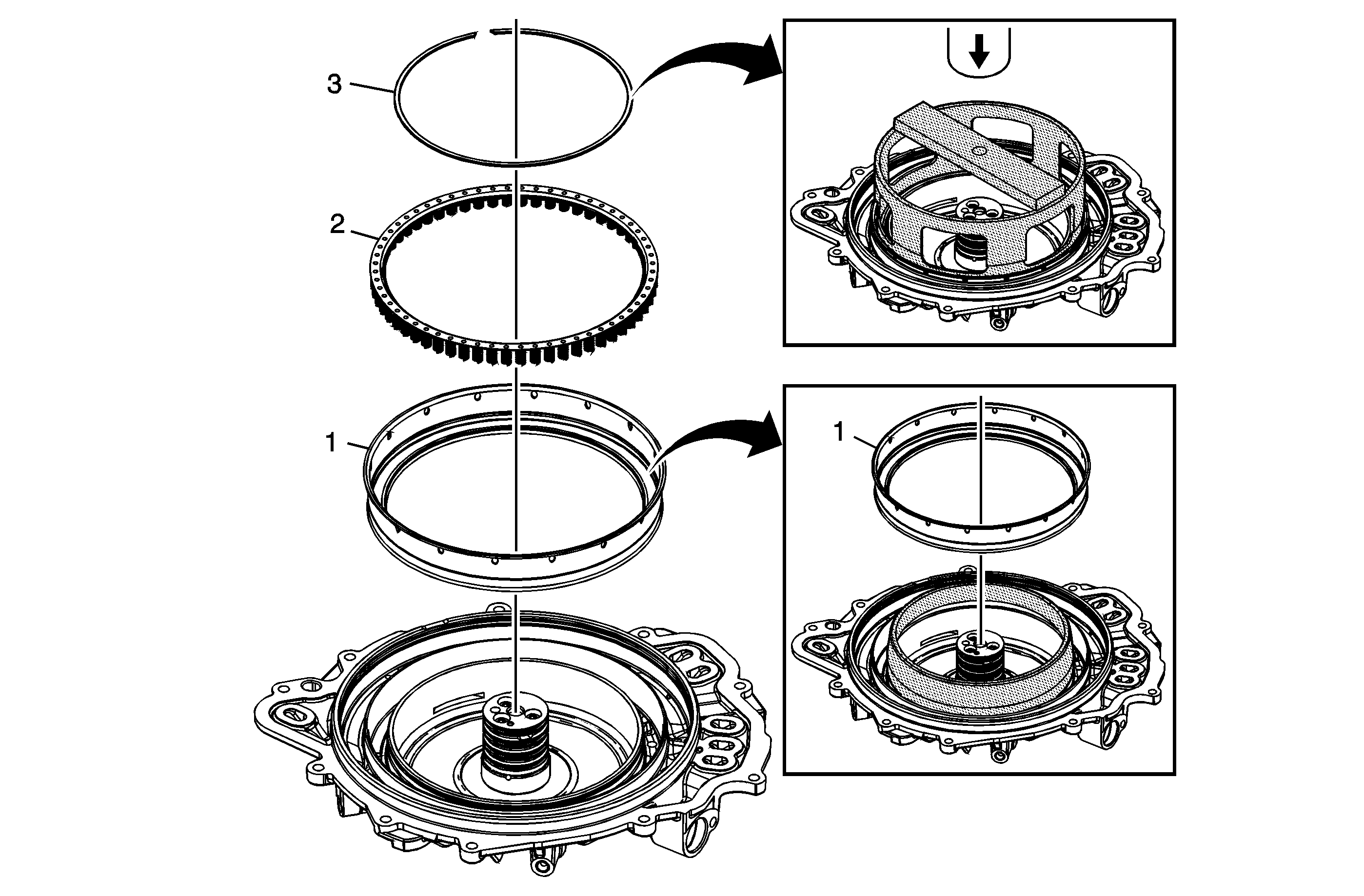
Callout | Component Name |
|---|---|
1 | 2-6 Clutch Piston ProcedureJ-46621 prevents the piston seal lip from damage over the retaining ring groove during installation. Apply a thin coat of ATF to the O.D. of J-46621 to ease the installation of the piston. Special ToolJ-46621 Seal Protector |
2 | 2-6 Clutch Spring Assembly |
3 | 2-6 Clutch Spring Assembly Procedure
Special ToolJ-46632 Spring Compressor |
Low and Reverse Clutch Piston Installation
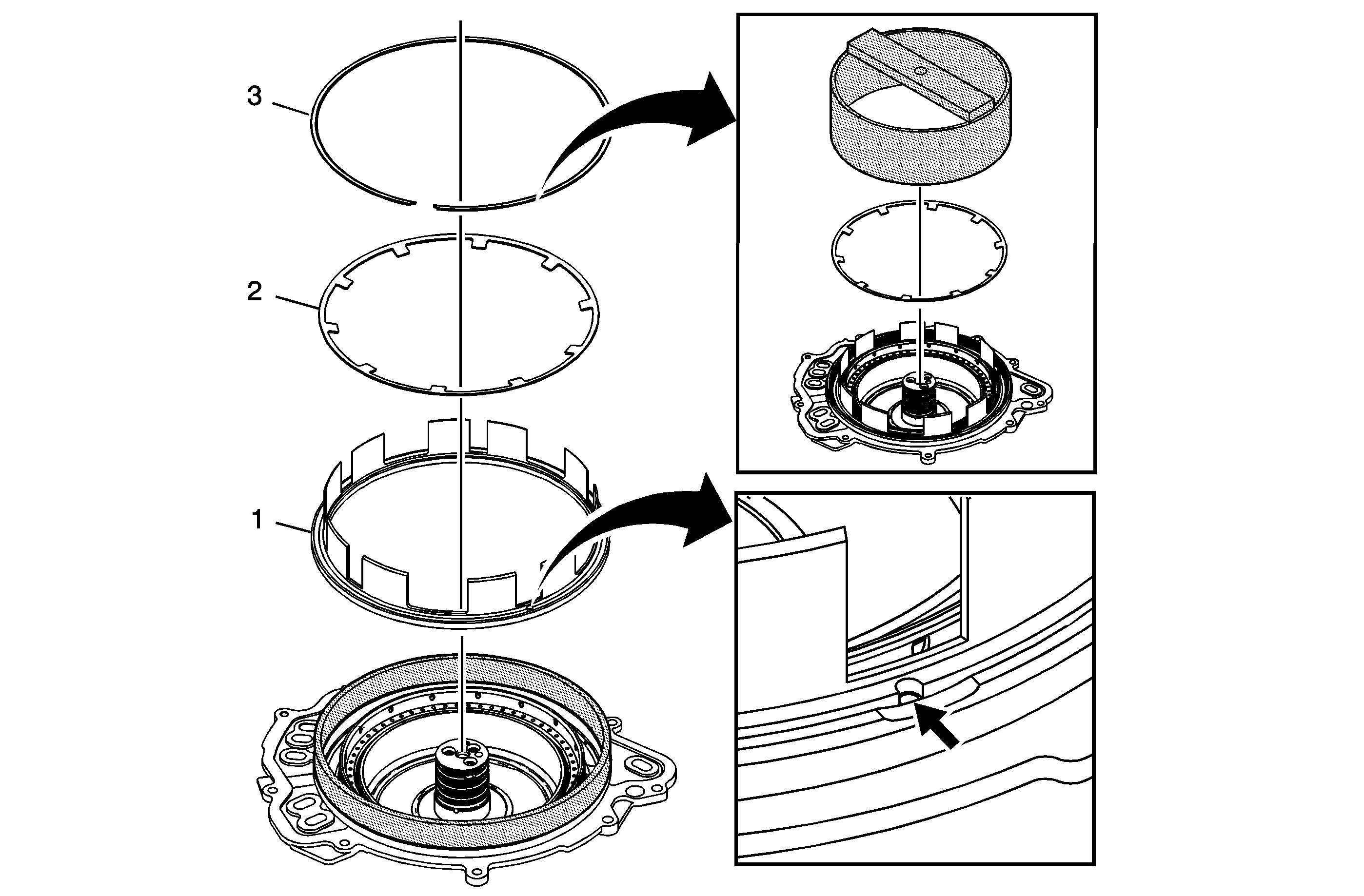
Callout | Component Name |
|---|---|
1 | Low and Reverse Clutch Piston Assembly Procedure
Special ToolJ-46628-1 Piston Seal Protector |
2 | Low and Reverse Clutch Spring |
3 | Low and Reverse Clutch Spring Retaining Ring Tip Special ToolJ-46628-2 Spring Compressor |
2-6 and Low-Reverse Piston Function Inspection
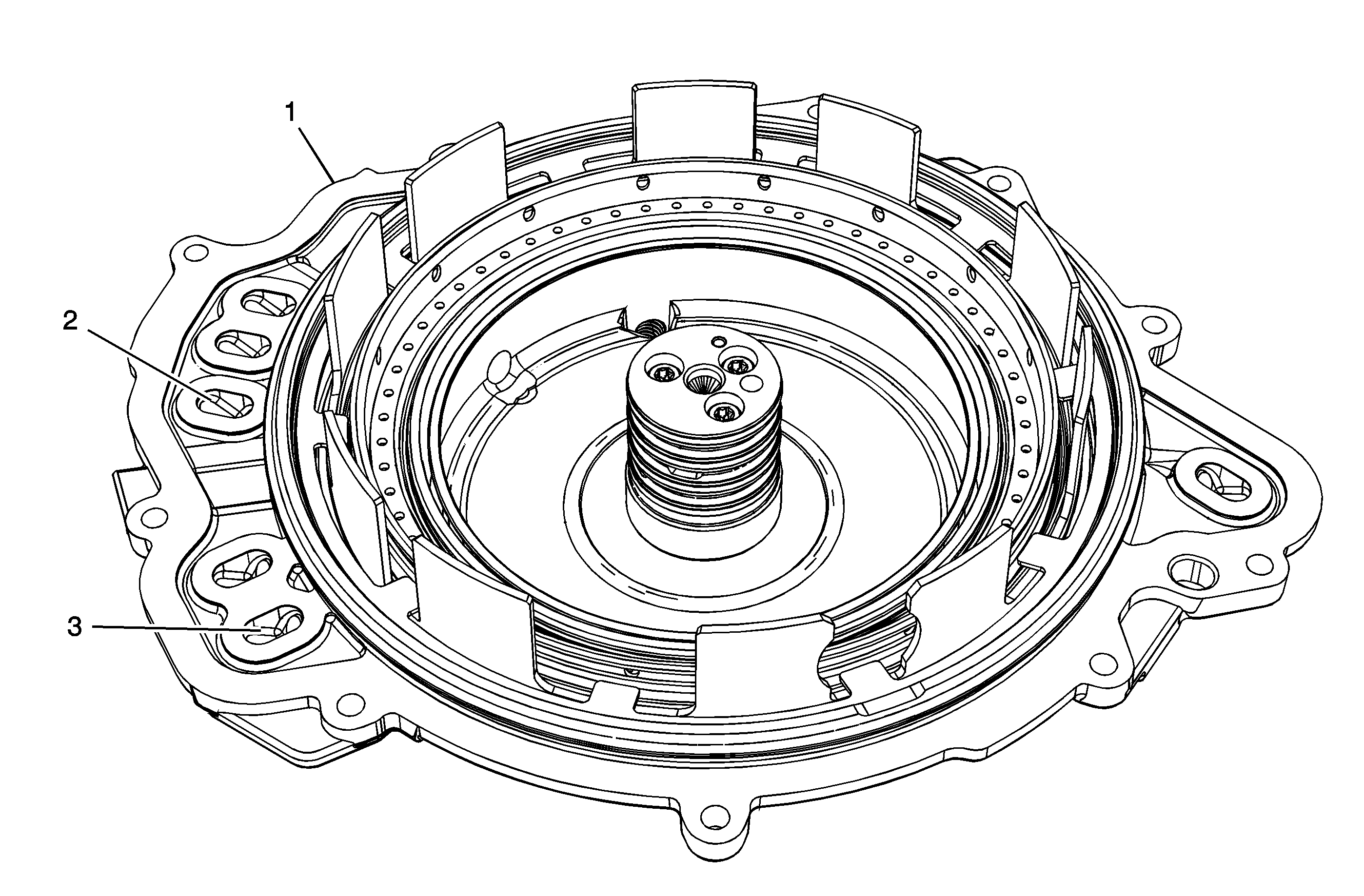
Callout | Component Name |
|---|---|
1 | Case Cover Assembly Tip |
2 | 2-6 Clutch Feed Passage Notice: Regulate the air pressure to 40 psi maximum. High pressure could cause the piston to over travel and damage the piston seals. ProcedureApply shop air to the 2-6 clutch feed. Observe the 2-6 piston movement. Tip |
3 | Low and Reverse Clutch Feed Passage Notice: Regulate the air pressure to 40 psi maximum. High pressure could cause the piston to over travel and damage the piston seals. ProcedureApply shop air to the Low and Reverse clutch feed. Observe the Low and Reverse piston movement. Tip |
Input Speed Sensor Installation
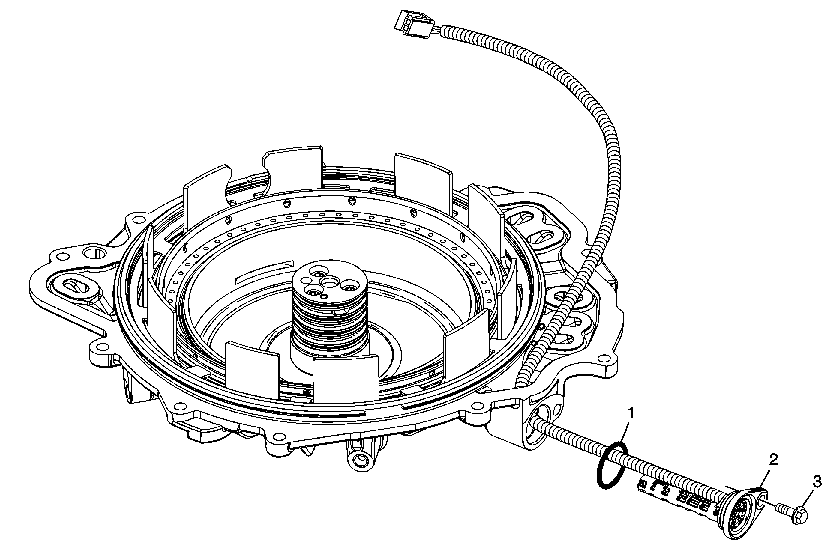
Callout | Component Name |
|---|---|
1 | Input Speed Sensor Seal |
2 | A/Trans Input Speed Sensor Assembly |
3 | A/Trans Input Speed Sensor Bolt M6 x 25 Notice: Refer to Fastener Notice in the Preface section. ProcedureApply threadlocker GM P/N 12345382 (Canadian P/N 10953489) or equivalent to the input speed sensor bolt. Tip Tighten |
