For 1990-2009 cars only
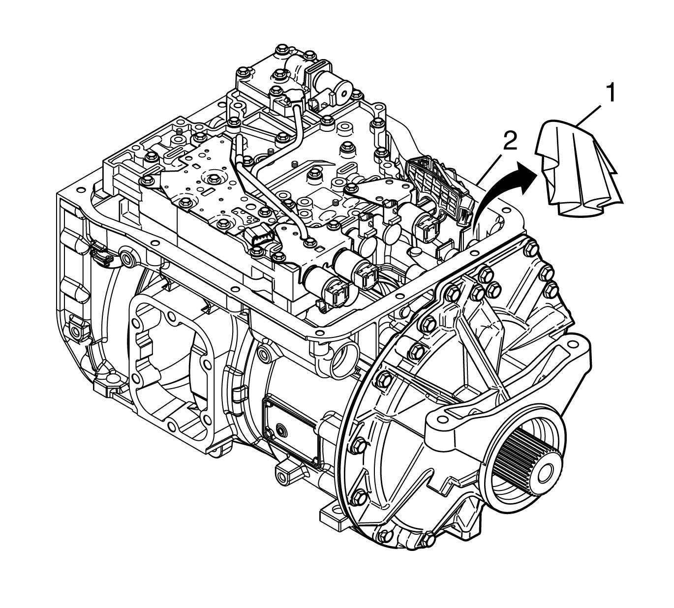
- Install a lint-free cloth (1) in the park pawl cam guide hole in the transmission case (2).
- Position the transmission case so that the valve body face of the transmission case is facing up.
- Align the manual valve pin (3) with the manual selector valve (2).
- Rotate the manual valve pin (3) until the pin can be installed into the manual selector valve.
- Install the manual valve pin (3) into the manual selector valve (2).
- Install the manual selector valve into shift valve body (1).
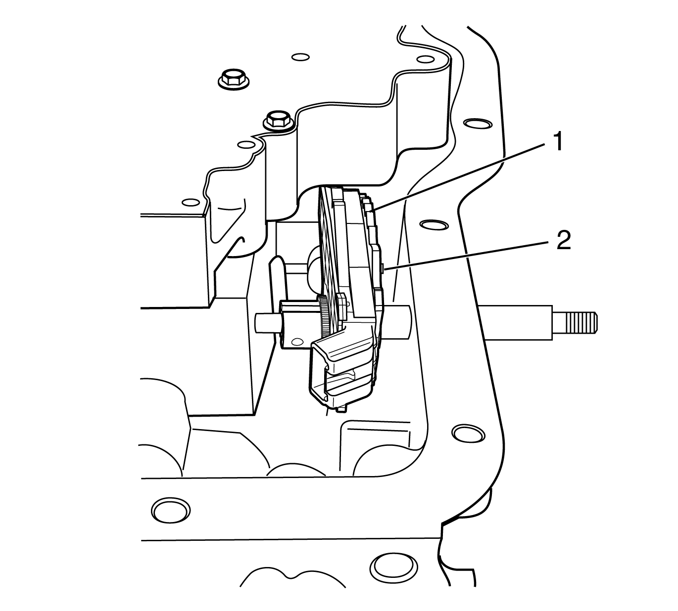
- Rotate the detent lever/internal mode switch (IMS) assembly to the fullest counter-clockwise position.
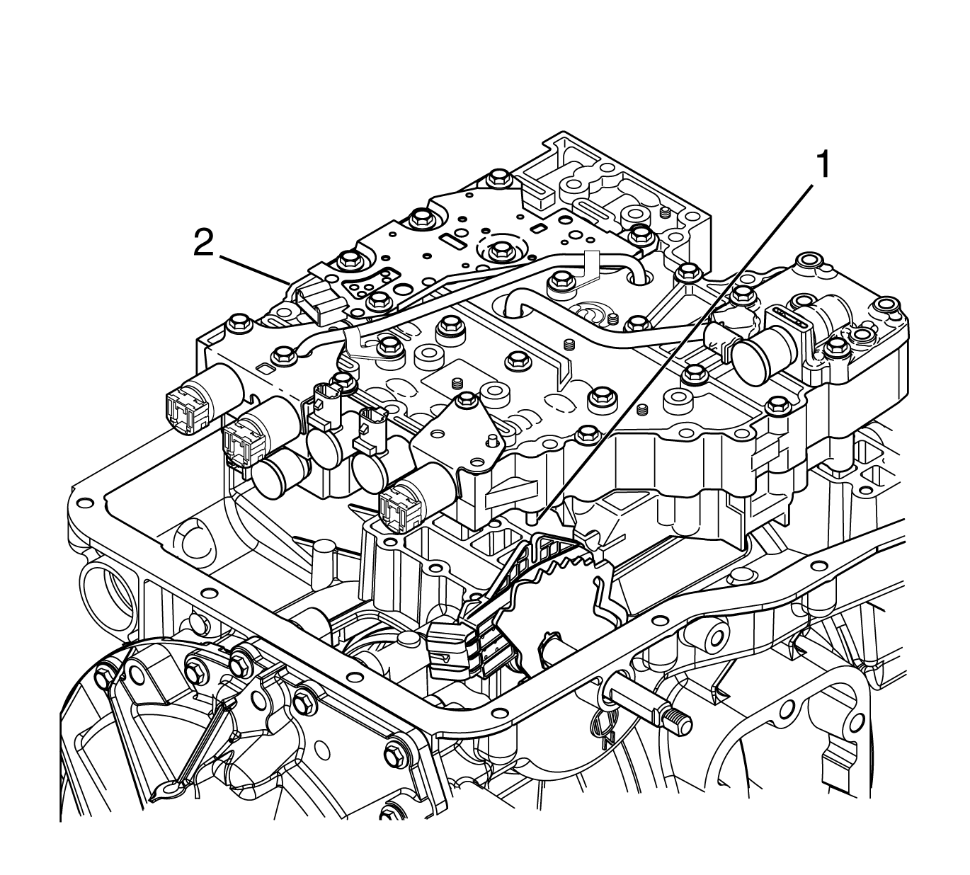
- Align the control valve assembly with the transmission case while installing the manual valve pin (2) into the detent lever/IMS assembly (1).
- Align 2 control valve assembly locating pins (1) with the locating pin holes in the transmission case.
- Install the control valve body assembly (2) onto the transmission case.
- Remove the lint-free cloth (1) from the park pawl cam guide hole.
- Install 11 control valve assembly bolts (1) and 4 control valve assembly bolts (2).
- Install the manual shift shaft detent spring (2) onto the main valve body (4).
- Make sure the pin of the manual shift shaft detent spring (2) engages the slot of the IMS and the detent spring roller rests on the detent lever (3).
- Install 2 manual shift shaft detent spring bolts (1).
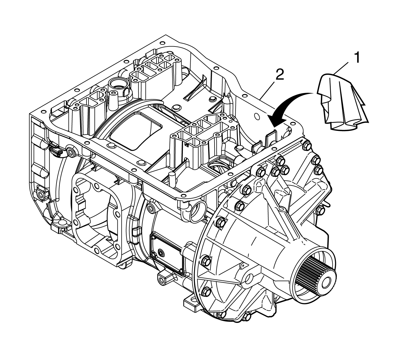
Important: Installing a lint-free cloth into the park pawl cam guide hole prevents the manual valve pin from falling into the transmission.
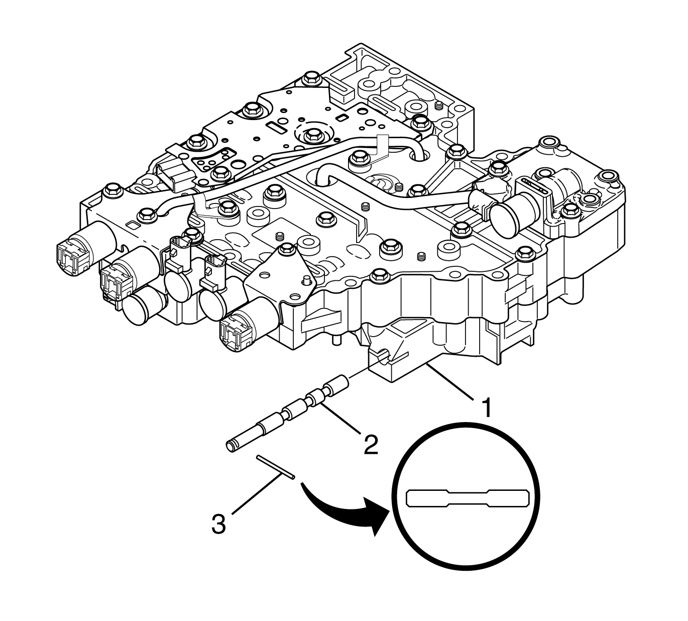
Important: Do not drop the manual valve when removing or installing the control valve assembly onto or from the transmission case.
Notice: Refer to Fastener Notice in the Preface section.
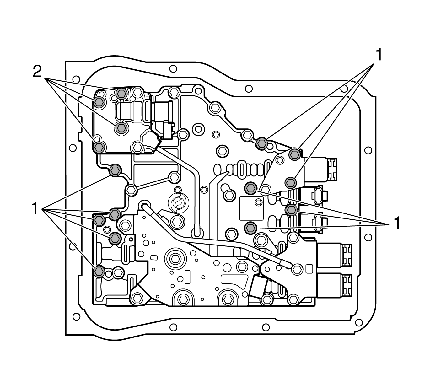
Tighten
Tighten the bolts to 12 N·m (108 lb in).
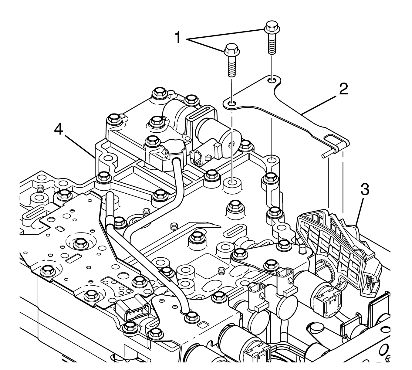
Tighten
Tighten the bolts to 12 N·m (108 lb in).
