For 1990-2009 cars only
Removal Procedure
- Disconnect the negative battery cable. Refer to Battery Negative Cable Disconnection and Connection in Engine Electrical.
- Remove the instrument panel (I/P) right side endcap cover. Refer to Upper Trim Pad, Outer Trim Cover, Fuse Block Access Cover Replacement - Instrument Panel in Instrument Panel, Gages, and Console.
- Remove the I/P compartment. Refer to Instrument Panel Compartment Assembly, Door, Striker, and Latch Replacement in Instrument Panel, Gages, and Console.
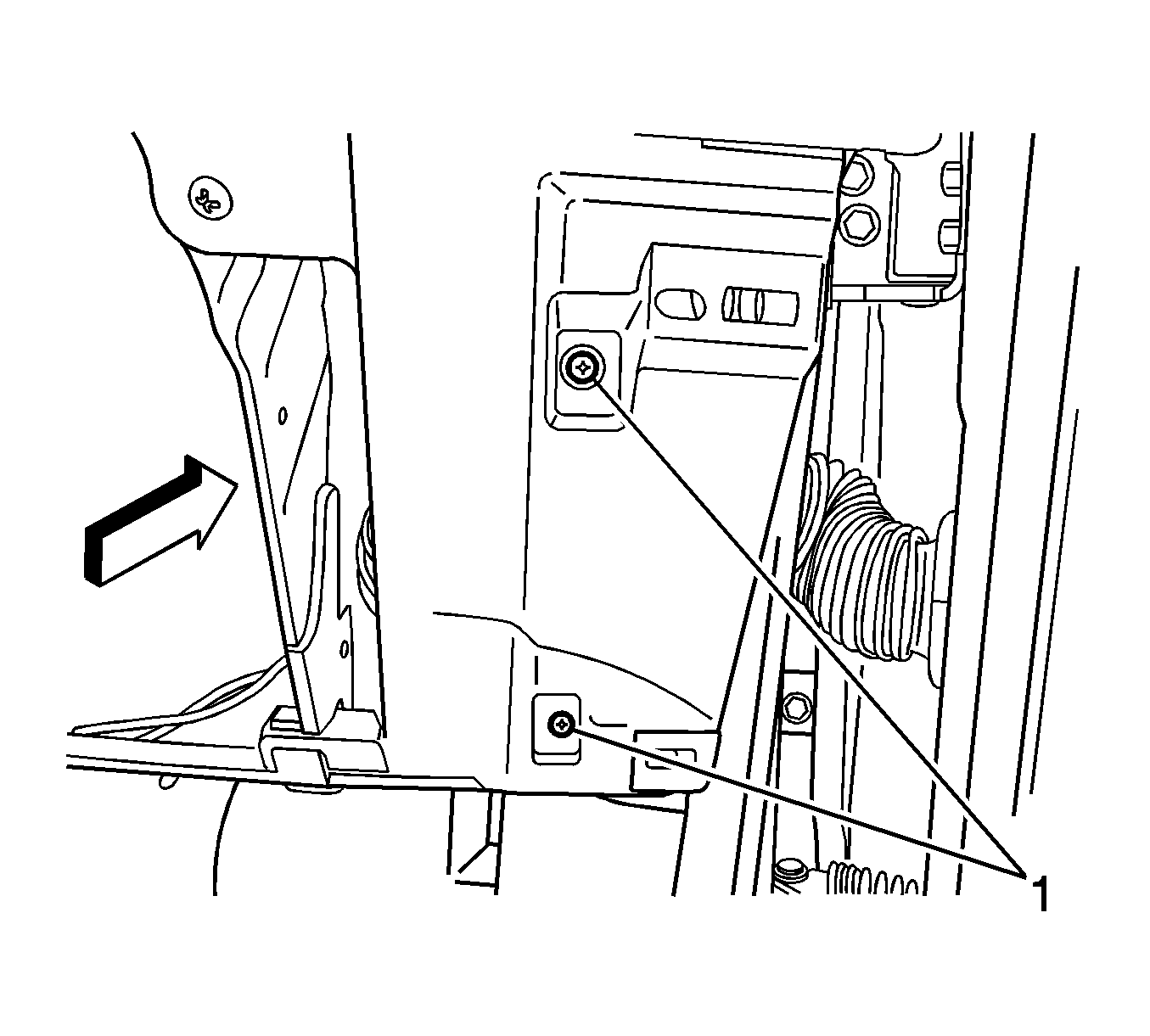
- Remove the 2 forward screws (1) securing the I/P accessory wiring junction block assembly to the I/P carrier.
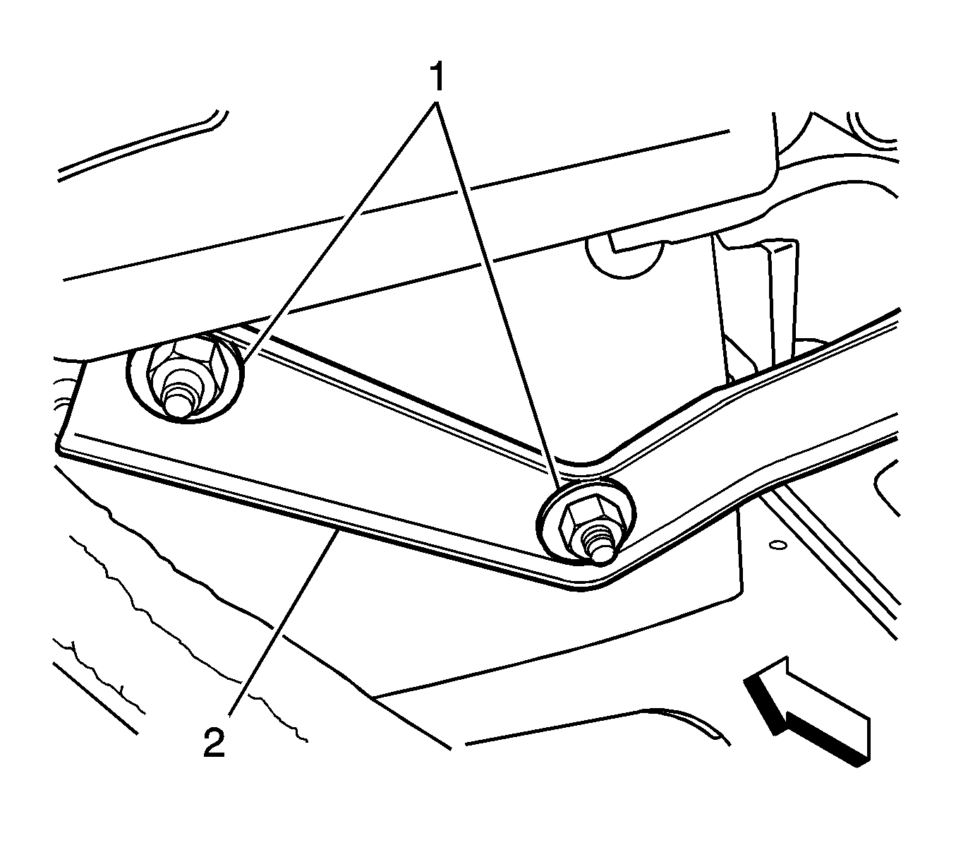
- Remove the 2 nuts (1) securing the I/P accessory wiring junction block assembly bracket (2) to the I/P carrier.
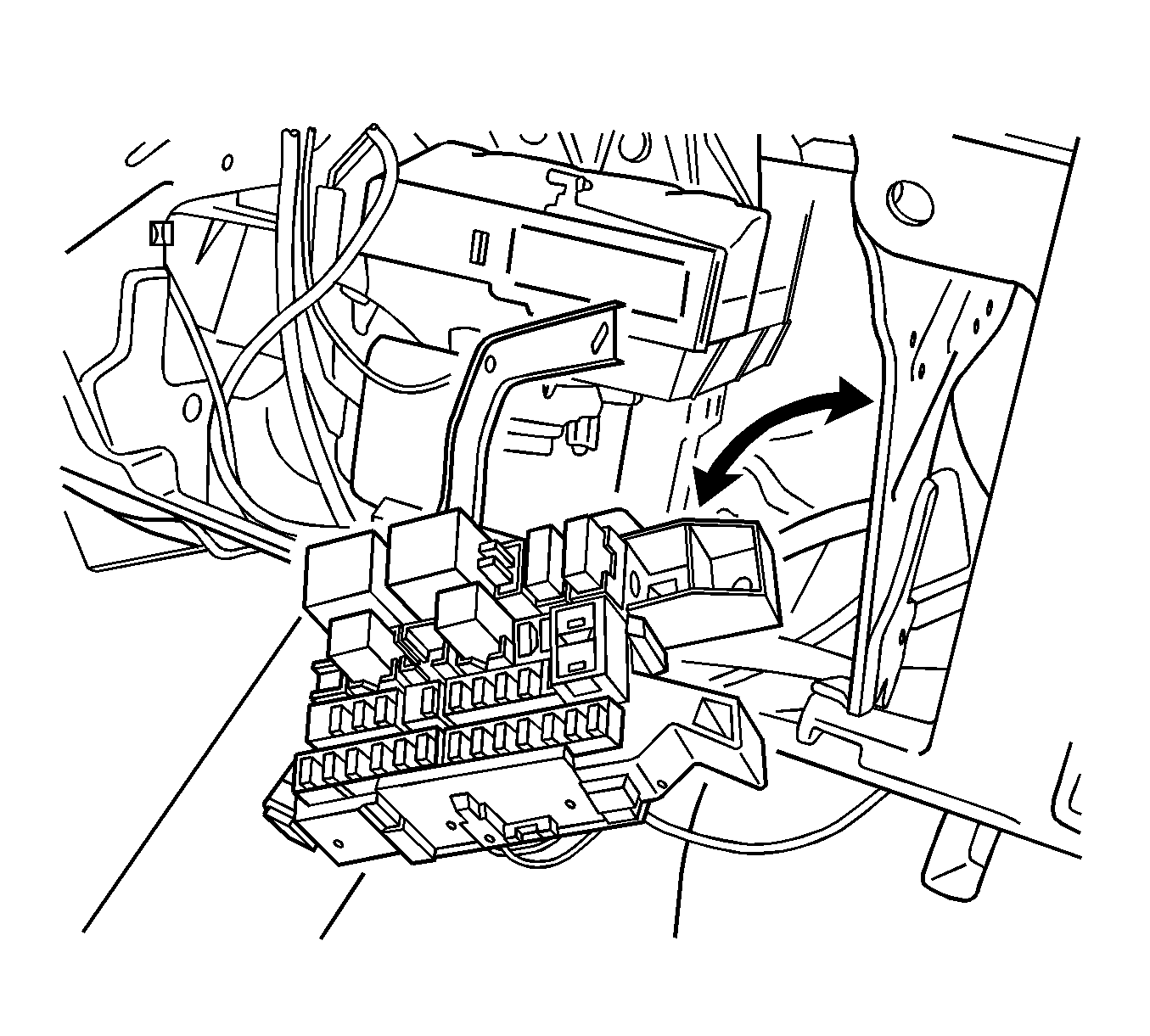
- Lower the I/P electrical center bracket and swing the junction block into the stowage compartment area.
- Squeeze and release the retaining tabs from the shroud/base in order to release the electrical connector from the I/P wiring harness.
- Walk off the I/P accessory wiring junction block assembly from the connector.
- Ensure the main harness is secured into the lower shroud/base.


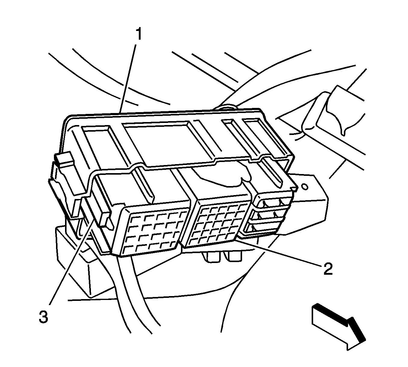
Important: Re-stage the connectors (2) into the lower I/P accessory wiring junction block assembly base/shroud (1) prior to installing the new I/P wiring harness junction block.
Installation Procedure
- Verify that the harness connectors are securely locked to the retention tabs (3).
- Position the connector (1) to the I/P wiring harness junction block.
- Once the connector is aligned, carefully squeeze the connector to the base until both outer locking tabs are secure.
- Repeat step 3 for the additional connectors.
- Position the I/P wiring harness junction block bracket (2) back to the I/P carrier bracket studs.
- Install the nuts (1).
- Secure the 2 screws (1) at the I/P endcap.
- Install the I/P compartment. Refer to Instrument Panel Compartment Assembly, Door, Striker, and Latch Replacement in Instrument Panel, Gages, and Console.
- Install the I/P right side end cap cover. Refer to Upper Trim Pad, Outer Trim Cover, Fuse Block Access Cover Replacement - Instrument Panel in Instrument Panel, Gages, and Console.
- Connect the negative battery cable. Refer to Battery Negative Cable Disconnection and Connection in Engine Electrical.
- Perform the power sliding door re-initialization procedure. Refer to Rear Side Door Actuator Control Module Programming and Setup .


Notice: Refer to Fastener Notice in the Preface section.
Tighten
Tighten the nuts to 10 N·m (89 lb in).

Tighten
Tighten the screws to 2 N·m (18 lb in).
