For 1990-2009 cars only
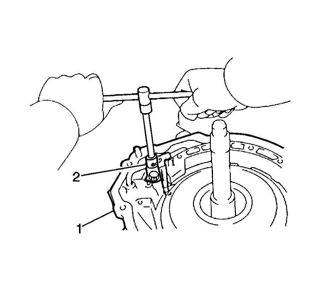
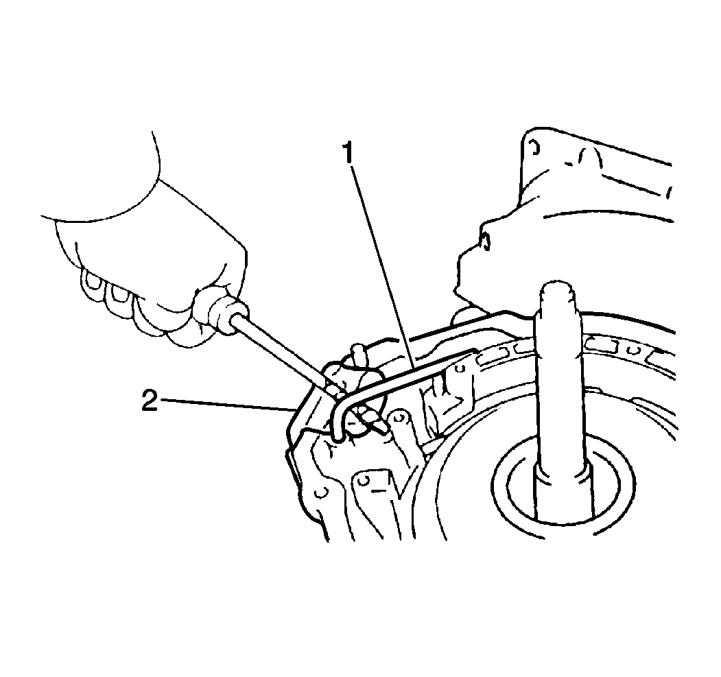
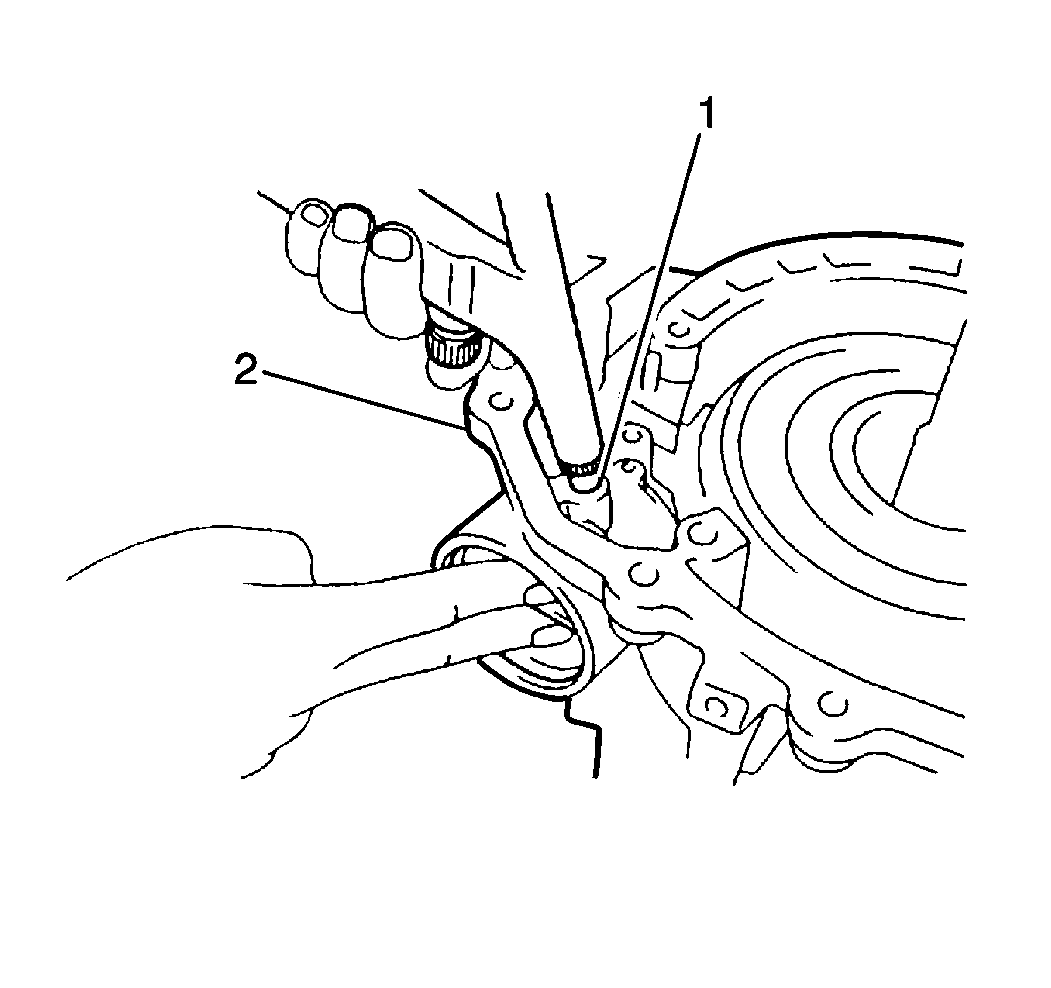
- Remove the 1 bolt and the second coast brake apply pipe bracket (2) from the transaxle case (1).
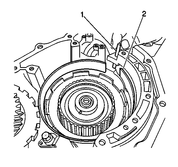
- Remove the 2nd coast brake apply pipe (1) from the transaxle case (2).
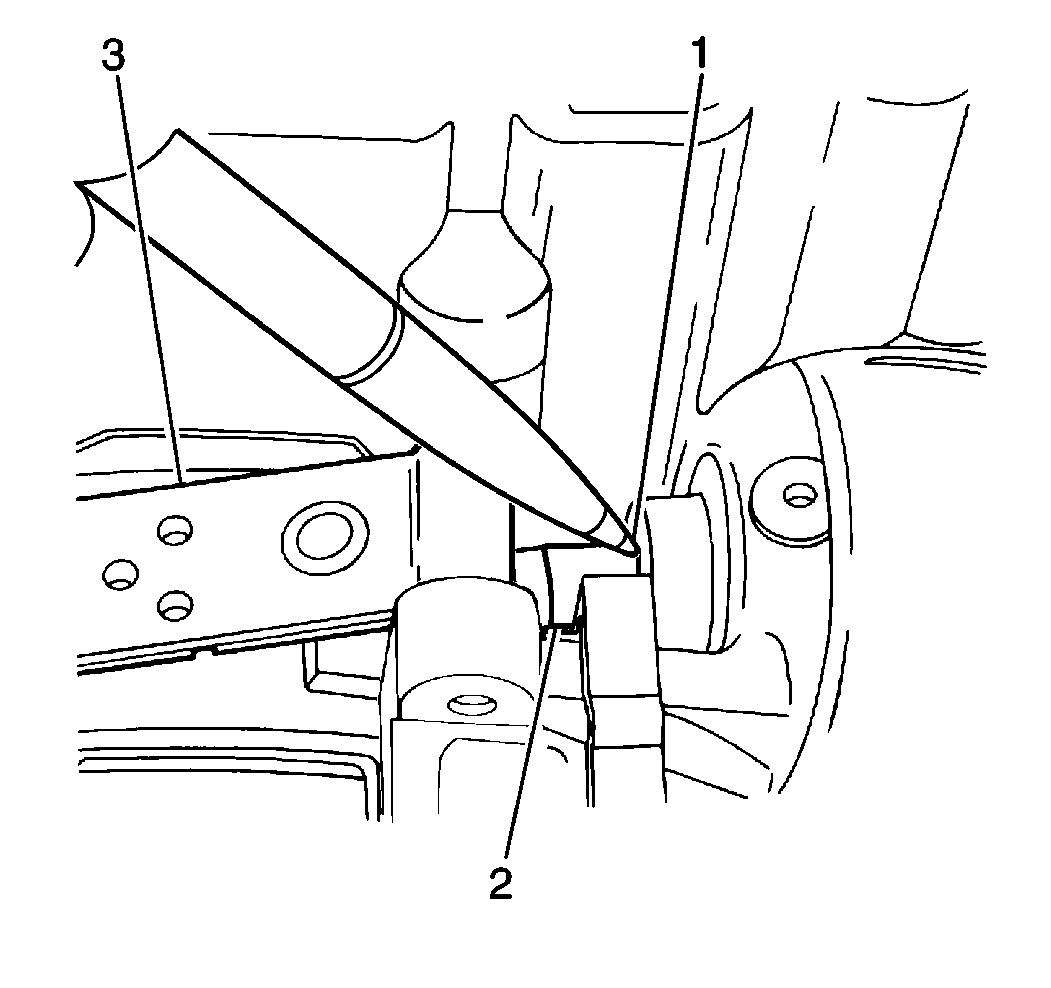
- Place a reference mark (1) on the 2nd coast brake piston rod (2) where the piston rod meets the transaxle case.
- Apply 392-785 kPa (57-114 psi) of compressed air into the 2nd coast brake apply passage (2).
- Measure the distance between the reference mark and the transaxle case using a feeler gage (1) to obtain the 2nd coast brake piston stroke.
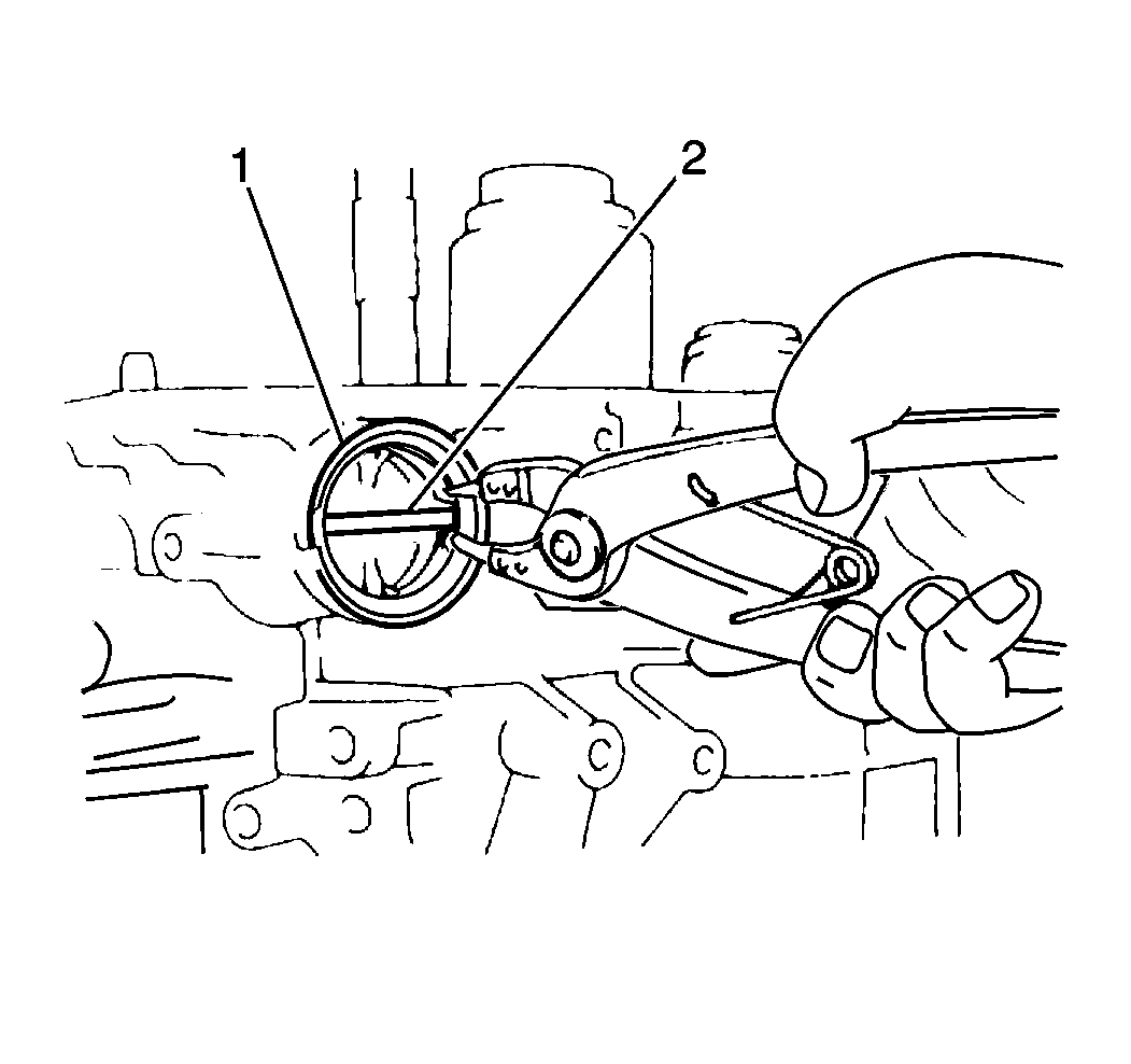
- Remove the 2nd coast brake servo cover snap ring (1) from the transaxle case.
- Remove the following components from the transaxle case (2) by slowly applying low pressure compressed air into the 2nd coast brake servo apply passage (1):
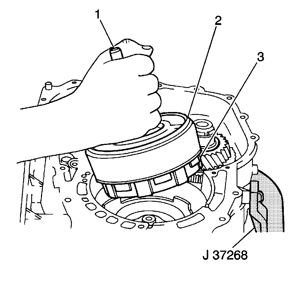
- Remove the forward and direct clutch assemblies (3, 2) from the transaxle case by grasping the input shaft (1) and lifting the shaft upward.
- Remove the 2nd coast brake band anchor pin (2) from the transaxle case (1).
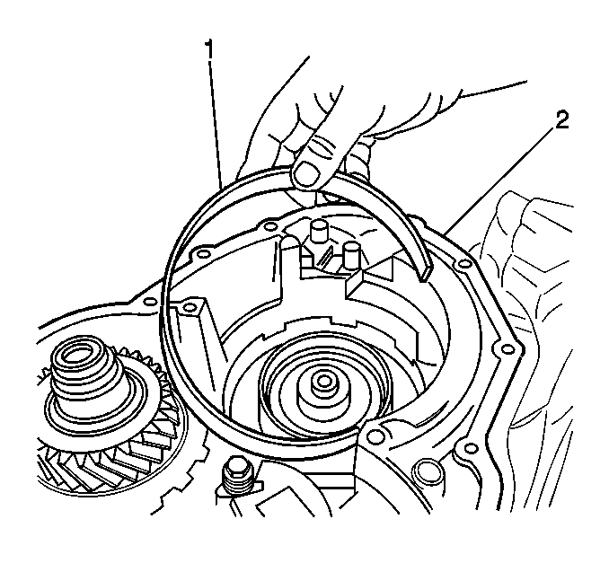
- Remove the 2nd coast brake band from the transaxle case (1).
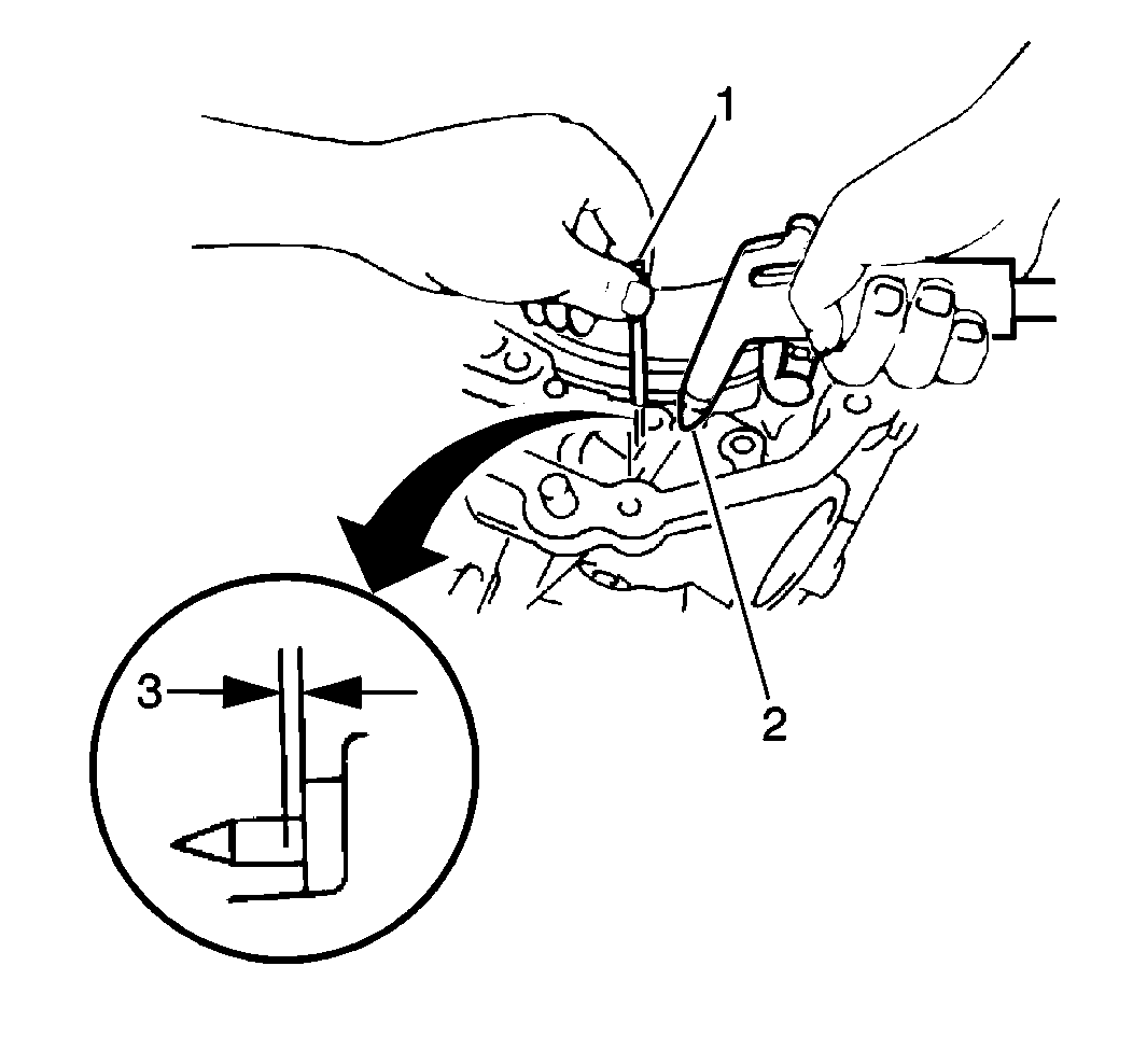
| • | The 2nd coast brake piston stroke should fall within 1.5-3.5 mm (0.059-0.138 in) (3) |
| • | If the 2nd coast brake piston stroke exceeds specification, inspect the 2nd coast brake band for excessive wear or damage |
Important: When using compressed air to remove components, air pressure should not exceed 98 kPa (14psi).
| • | The 2nd coast brake servo cover |
| • | The 2nd coast brake piston |
| • | The 2nd coast brake piston outer return spring |
