For 1990-2009 cars only
Removal Procedure
Notice: Do not use solvent of any type when cleaning the gasket surfaces on the intake manifold and the throttle body assembly, as damage to the gasket surfaces and throttle body assembly may result.
Use care in cleaning the gasket surfaces on the intake manifold and the throttle body assembly, as sharp tools may damage the gasket surfaces.Notice: Do not use any solvent that contains Methyl Ethyl Ketone (MEK). This solvent may damage fuel system components.
- Remove the charge air cooler outlet pipe. Refer to Charge Air Cooler Outlet Pipe Replacement.
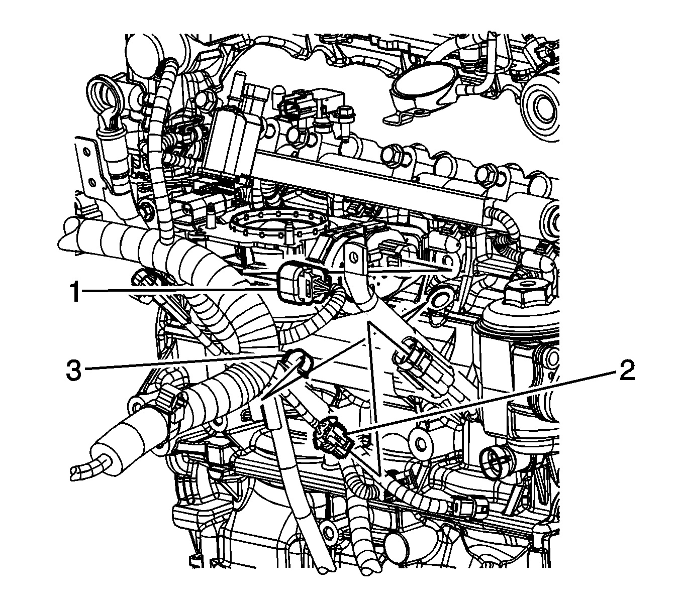
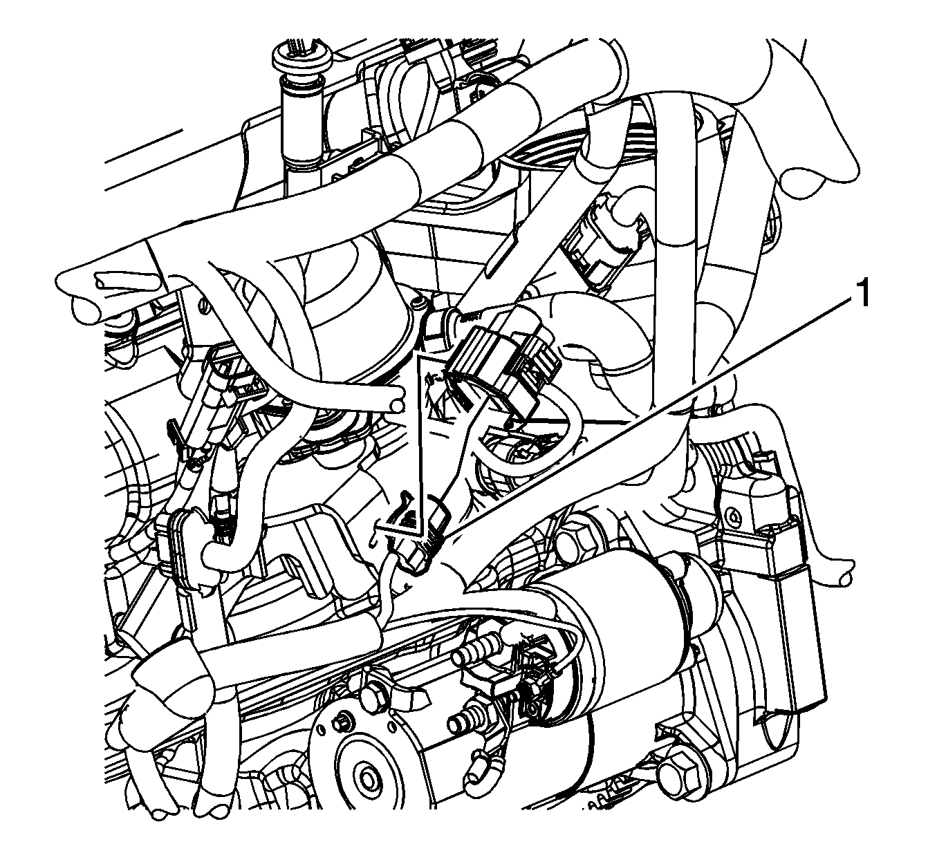
- Disconnect the engine wiring harness electrical connector (1) from the electronic throttle control (ETC).
- Disconnect the engine wiring harness electrical connector (1) from the brake booster auxiliary pump, if equipped.
- Remove the brake booster auxiliary pump electrical connector clip from the bracket.
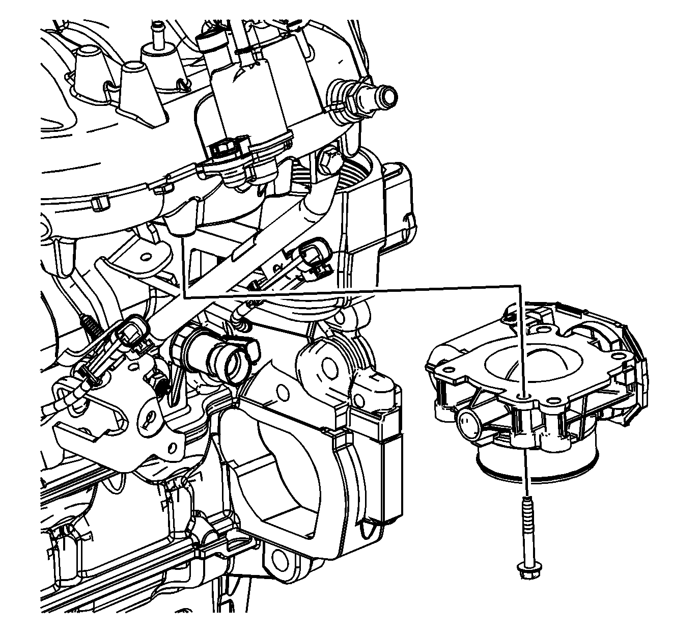
- Remove the throttle body bolts.
- Remove the throttle body and seal from the intake manifold.


Installation Procedure
- Inspect the throttle body seal, and replace if necessary.
- Position the throttle body to the intake manifold.
- Install the throttle body bolts.
- Connect the engine wiring harness electrical connector (1) to the brake booster auxiliary pump, if equipped.
- Install the brake booster auxiliary pump electrical connector clip to the bracket.
- Connect the engine wiring harness electrical connector (1) to the ETC.
- Install the charge air cooler outlet pipe. Refer to Charge Air Cooler Outlet Pipe Replacement.

Notice: Refer to Fastener Notice in the Preface section.
Tighten
Tighten the bolts to 10 N·m (89 lb in).


